JP2005331027A - Railway vehicle gear device and railway vehicle carriage - Google Patents
Railway vehicle gear device and railway vehicle carriage Download PDFInfo
- Publication number
- JP2005331027A JP2005331027A JP2004149411A JP2004149411A JP2005331027A JP 2005331027 A JP2005331027 A JP 2005331027A JP 2004149411 A JP2004149411 A JP 2004149411A JP 2004149411 A JP2004149411 A JP 2004149411A JP 2005331027 A JP2005331027 A JP 2005331027A
- Authority
- JP
- Japan
- Prior art keywords
- gear
- railway vehicle
- bearing lid
- plate portion
- vibration
- Prior art date
- Legal status (The legal status is an assumption and is not a legal conclusion. Google has not performed a legal analysis and makes no representation as to the accuracy of the status listed.)
- Pending
Links
Images





Classifications
-
- F—MECHANICAL ENGINEERING; LIGHTING; HEATING; WEAPONS; BLASTING
- F16—ENGINEERING ELEMENTS AND UNITS; GENERAL MEASURES FOR PRODUCING AND MAINTAINING EFFECTIVE FUNCTIONING OF MACHINES OR INSTALLATIONS; THERMAL INSULATION IN GENERAL
- F16C—SHAFTS; FLEXIBLE SHAFTS; ELEMENTS OR CRANKSHAFT MECHANISMS; ROTARY BODIES OTHER THAN GEARING ELEMENTS; BEARINGS
- F16C33/00—Parts of bearings; Special methods for making bearings or parts thereof
- F16C33/72—Sealings
- F16C33/723—Shaft end sealing means, e.g. cup-shaped caps or covers
-
- F—MECHANICAL ENGINEERING; LIGHTING; HEATING; WEAPONS; BLASTING
- F16—ENGINEERING ELEMENTS AND UNITS; GENERAL MEASURES FOR PRODUCING AND MAINTAINING EFFECTIVE FUNCTIONING OF MACHINES OR INSTALLATIONS; THERMAL INSULATION IN GENERAL
- F16C—SHAFTS; FLEXIBLE SHAFTS; ELEMENTS OR CRANKSHAFT MECHANISMS; ROTARY BODIES OTHER THAN GEARING ELEMENTS; BEARINGS
- F16C2326/00—Articles relating to transporting
- F16C2326/10—Railway vehicles
-
- F—MECHANICAL ENGINEERING; LIGHTING; HEATING; WEAPONS; BLASTING
- F16—ENGINEERING ELEMENTS AND UNITS; GENERAL MEASURES FOR PRODUCING AND MAINTAINING EFFECTIVE FUNCTIONING OF MACHINES OR INSTALLATIONS; THERMAL INSULATION IN GENERAL
- F16C—SHAFTS; FLEXIBLE SHAFTS; ELEMENTS OR CRANKSHAFT MECHANISMS; ROTARY BODIES OTHER THAN GEARING ELEMENTS; BEARINGS
- F16C2361/00—Apparatus or articles in engineering in general
- F16C2361/61—Toothed gear systems, e.g. support of pinion shafts
Landscapes
- Engineering & Computer Science (AREA)
- General Engineering & Computer Science (AREA)
- Mechanical Engineering (AREA)
- General Details Of Gearings (AREA)
- Mounting Of Bearings Or Others (AREA)
- Sealing Of Bearings (AREA)
Abstract
【課題】 大歯車と小歯車の噛み合いによる回転で発生する歯車箱の振動によって小歯車側の軸受ふたが共振するのを低減する。
【解決手段】 鉄道車両用歯車装置3において、小歯車3aa側の軸受ふた3caの固有振動数が、当該鉄道車両の最高車両速度に対応する大歯車3bと小歯車3aaとの噛み合い周波数より大きくなるように、前記軸受ふた3caの板部の剛性を高める。
【効果】 鉄道車両用歯車装置の基本構成の変更や大幅な重量増加を伴わずに、その歯車箱の振動、さらにはこの振動によって生じる騒音を可及的に小さくできる。
【選択図】 図1
PROBLEM TO BE SOLVED: To reduce resonance of a bearing lid on a small gear side by vibration of a gear box generated by rotation caused by meshing of a large gear and a small gear.
In a railway vehicle gear device 3, the natural frequency of a bearing lid 3ca on the small gear 3aa side becomes larger than the meshing frequency of the large gear 3b and the small gear 3aa corresponding to the maximum vehicle speed of the railway vehicle. As described above, the rigidity of the plate portion of the bearing lid 3ca is increased.
[Effect] The vibration of the gear box and the noise caused by the vibration can be minimized as much as possible without changing the basic configuration of the gear unit for a railway vehicle and increasing the weight.
[Selection] Figure 1
Description
本発明は、鉄道車両用歯車装置において、歯車箱の振動及び騒音を低減可能な歯車装置、及び、この歯車装置を搭載した鉄道車両用台車に関するものである。 The present invention relates to a gear device capable of reducing vibration and noise of a gear box in a rail vehicle gear device, and a rail vehicle carriage equipped with the gear device.
近年、鉄道車両に対しては、より一層の高速性が求められているが、高速性を求めると、車両振動が増大するので、振動によって発生する路線周辺への騒音低減、さらには乗客の乗り心地改善等への対応が必要になる。 In recent years, there has been a demand for higher speeds for railway vehicles. However, when high speeds are required, vehicle vibration increases, reducing noise around the route caused by vibrations, and even passengers It is necessary to deal with comfort improvement.
鉄道車両は、図13に示すように、モータ1が発生するトルクを、たわみ軸継手2を介して歯車装置3の小歯車軸(ピニオン軸ともいう)3aに伝達し、この小歯車軸3aに形成した小歯車3aaに噛み合う大歯車3bを経て車軸4に取り付けた車輪5に伝達し、走行するようになっている。
As shown in FIG. 13, the railway vehicle transmits the torque generated by the
ところで、前記歯車装置3の内部では、モータ1が発生するトルクによって絶えず小歯車3aと大歯車3bが回転しているため、その回転によって絶えず振動していることになるが、この歯車装置3に発生する振動・騒音を低減させる手段としては、たとえば次のようなものがある。
By the way, since the
1)歯車吊り装置の動揺を防止する目的で、台車枠の吊り受けに対する吊りリンクの動揺を防止可能な歯車箱吊り装置。
2)吊り装置に対して乗り心地改善に必要な軸ばね剛性を付与できる支持装置。
3)軸受構造を改良し、無負荷及び軽負荷時に軸受隙間によるがたつきが原因であるすりこぎ運動に起因して発生する振動や騒音を低減させる歯車装置。
4)歯車装置の支持をピニオン軸の軸心に一致或いは極めて近づけることによりピニオン軸の移動量を小さくしつつ、ブラケットからピニオン軸までの距離を短くすることによって自在継手の変位を小さくし、歯車箱の振動を台車枠に伝えにくくする歯車箱の支持装置。
これらの発明はいずれも軸受のがたつきを低減させることによって歯車装置の制振を図る、或いは、歯車装置の振動は許容しつつその伝達を阻止することが目的である。 The purpose of any of these inventions is to reduce vibration of the bearing by reducing the rattling of the bearing, or to prevent transmission of the gear apparatus while allowing vibration of the gear apparatus.
解決しようとする問題点は、従来の鉄道車両用歯車装置における振動や騒音の低減手段では、大歯車と小歯車が噛み合って発生する歯車箱の振動と、小歯車側の軸受ふたが共振することで、前記振動や騒音が大きくなるという点についての考慮はなされていなかったという点である。 The problem to be solved is that with the vibration and noise reduction means in the conventional railway vehicle gear device, the vibration of the gear box generated by the meshing of the large gear and the small gear resonates with the bearing lid on the small gear side. However, no consideration has been given to the fact that the vibration and noise increase.
(大歯車と小歯車の噛み合い周波数と軸受ふたが共振を起こす理由について)
本発明が対象とする歯車装置は回転機械である。回転機械に発生した原因を調査する際、多くの場合はまず測定した振動の時刻歴データに含まれている振動数成分を調査し、それらの振動数と回転速度(回転数)との関係に注目し、その結果を整理・検討する。
(About the meshing frequency of the large gear and the small gear and the reason why the bearing lid resonates)
The gear device targeted by the present invention is a rotating machine. When investigating the cause of a rotating machine, in many cases, the frequency component contained in the measured time history data is first investigated, and the relationship between the frequency and the rotational speed (rotation speed) is examined. Pay attention and organize and review the results.
そこで、まず、発明者らは歯車装置の振動及び騒音の低減を目的に改良案を数多く検討した上で回転試験を行い、その結果を整理したところ、モータ回転数に対して軸受ふたの加速度が特異的に大きくなることを知見した。以下、まず、本発明が対象としている軸受ふたについて説明する。 Therefore, first, the inventors examined a number of improvements for the purpose of reducing the vibration and noise of the gear device, conducted a rotation test, and organized the results. It was found to be specifically large. Hereinafter, the bearing lid which is the subject of the present invention will be described first.
図1は鉄道車両用歯車装置の一例を示す図を、公知文献である特開平7−113459号公報から引用したものである。この図1は上ふたを取り外し、かつ、一部を割断して示したものであり、車軸4に固定された大歯車3bと、この大歯車3bと噛み合うモータに連結される小歯車3aaとを歯車箱3c内に収容している。
FIG. 1 is a diagram showing an example of a railway vehicle gear device, which is cited from Japanese Laid-Open Patent Publication No. 7-113659, which is a publicly known document. FIG. 1 shows an upper cover removed and a part thereof cut off. A
この歯車箱3cは車体への取り付け部などを省略しているが、軸受3d,3eを収容する小歯車側と大歯車側の各軸受ふた3ca,3cbがボルトによって歯車箱3cに取り付けられている。
Although the gear box 3c does not have a mounting portion to the vehicle body, the small gear side and large gear side bearing lids 3ca and 3cb for housing the
発明者らは、回転試験の結果、前記軸受ふた3ca,3cbのうちの、図2に示すような断面形状を有する小歯車側の軸受ふた3caに関して加速度が特異的に大きくなることを見出した。 As a result of the rotation test, the inventors have found that, among the bearing lids 3ca and 3cb, the acceleration is specifically increased with respect to the bearing lid 3ca on the small gear side having a cross-sectional shape as shown in FIG.
図3に歯車装置の回転試験で得られた結果の一例を示す。図3中のaのモータ回転数では、小歯車側の軸受ふたの左右振動(太い実線)が、また、bのモータ回転数では、小歯車側の軸受ふたの上下振動(細い実線)が、同じ図3に示した小歯車軸の上下振動(破線)に比較して特異的に高くなっている。そして、図3のcで示した範囲は、モータの回転数から歯車の噛み合い周波数に換算すると、前記軸受ふたが有する固有振動数に極めて近接していることが明らかとなった。 FIG. 3 shows an example of the results obtained in the rotation test of the gear device. In FIG. 3, at the motor speed of a, the left-right vibration (thick solid line) of the bearing lid on the small gear side, and at the motor speed of b, vertical vibration (thin solid line) of the bearing lid on the small gear side is It is specifically higher than the vertical vibration (broken line) of the small gear shaft shown in FIG. The range indicated by c in FIG. 3 was found to be very close to the natural frequency of the bearing lid when converted from the rotational speed of the motor to the meshing frequency of the gear.
この回転試験の結果から得られる知見を整理すると、一般に歯車の噛み合いによって生じる振動周波数を噛み合い周波数というが、この噛み合い周波数と小歯車側の軸受ふたの固有振動数が共振現象を起こし、図3に示した特異的な加速度振動が得られたと推定できるに至った。 When the knowledge obtained from the results of this rotation test is organized, the vibration frequency generated by the meshing of the gears is generally called the meshing frequency. It was possible to estimate that the specific acceleration vibration shown was obtained.
ここで、噛み合い周波数fG(Hz)とは、車両速度V(mm/分)から次式で求めることができる。
fG=(V/πD)・(n/60)
但し、D:車輪径(mm)
n:大歯車の歯数
Here, the meshing frequency fG (Hz) can be obtained from the vehicle speed V (mm / min) by the following equation.
fG = (V / πD) · (n / 60)
However, D: Wheel diameter (mm)
n: Number of teeth of large gear
次に、発明者らは本発明の対象である歯車装置の実験結果を整理した。図4にウォータフォール図を示す。この図4は、発生する振動数と、その振幅の大きさ及びモータの回転速度との関係について示した図である。 Next, the inventors arranged the experimental results of the gear device that is the subject of the present invention. FIG. 4 shows a waterfall diagram. FIG. 4 is a diagram showing the relationship between the generated frequency, the magnitude of the amplitude, and the rotational speed of the motor.
この図4より、モータ回転速度の増加に伴って、大歯車と小歯車の噛み合い周波数は大きくなり、さらにその発生振幅も大きくなることが判明した。一方、小歯車側の軸受ふたの固有振動数は、モータの回転速度の増加に対してその振動周波数は変動せず、また、その振幅も、増減はあるもののモータの回転数には無関係であった。 As can be seen from FIG. 4, the meshing frequency of the large gear and the small gear increases as the motor rotation speed increases, and the generated amplitude also increases. On the other hand, the natural frequency of the bearing lid on the small gear side does not fluctuate with respect to an increase in the rotational speed of the motor, and its amplitude is not related to the rotational speed of the motor, although there is an increase or decrease. It was.
この図4を実際の車両走行時に当てはめると、車両速度の増大、すなわち、モータ回転数の増加に合わせて大歯車と小歯車の噛み合い周波数が増加する。そして、この増加している噛み合い周波数が小歯車側の軸受ふたの固有振動数と一致する周波数(図4のA部)で共振現象が発生して歯車箱すなわち歯車装置の振動は最大となり、さらにこの振動から発せられる騒音が最大となる。 When FIG. 4 is applied during actual vehicle travel, the meshing frequency of the large gear and the small gear increases as the vehicle speed increases, that is, the motor speed increases. A resonance phenomenon occurs at a frequency (A part in FIG. 4) where the increased meshing frequency matches the natural frequency of the bearing lid on the small gear side, and the vibration of the gear box, that is, the gear device is maximized. The noise generated from this vibration is maximized.
以上のことから、歯車装置の振動や騒音を低減するためには、車両走行速度範囲においては、共振現象を起こす周波数を避けることが必要であることが判る。しかしながら、大歯車と小歯車の噛み合い周波数によって生じる歯車装置の振動は避けることができないため、歯車装置の振動や騒音の低減には、もう一つの原因、すなわち小歯車側の軸受ふたの固有振動数を変更して、共振現象を避けることが必要となる。 From the above, it can be seen that in order to reduce the vibration and noise of the gear device, it is necessary to avoid the frequency causing the resonance phenomenon in the vehicle traveling speed range. However, the gear unit vibration caused by the meshing frequency of the large gear and the small gear cannot be avoided. Therefore, another reason for reducing the gear unit vibration and noise is the natural frequency of the bearing lid on the small gear side. Therefore, it is necessary to avoid resonance phenomenon.
本発明の鉄道車両用歯車装置は、前述の知見に基づいてなされたものであり、
歯車箱の振動及び騒音を可及的に低減するため、
小歯車側の軸受ふたの固有振動数が、当該鉄道車両の最高車両速度に対応する大歯車と小歯車との噛み合い周波数に一致しないように、前記軸受ふたを構成した点を最も主要な特徴としている。
The railway vehicle gear device of the present invention is made based on the above-mentioned knowledge,
In order to reduce the vibration and noise of the gearbox as much as possible,
The main feature is that the bearing lid is configured such that the natural frequency of the bearing lid on the small gear side does not match the meshing frequency of the large gear and the small gear corresponding to the maximum vehicle speed of the railway vehicle. Yes.
前記共振現象は、経験的に固有振動数の±10%の範囲で発生するので、固有振動数の±10%の範囲の周波数と噛み合い周波数が一致しないようにする必要がある。従って、前記本発明において、小歯車側の軸受ふたの固有振動数が噛み合い周波数に一致しないとは、固有振動数の±10%の範囲と対象とする噛み合い周波数が重ならないことを意味するものとする。 Since the resonance phenomenon occurs empirically in the range of ± 10% of the natural frequency, it is necessary to prevent the meshing frequency from matching the frequency in the range of ± 10% of the natural frequency. Therefore, in the present invention, the fact that the natural frequency of the bearing lid on the small gear side does not coincide with the meshing frequency means that the target meshing frequency does not overlap with the range of ± 10% of the natural frequency. To do.
鉄道車両用歯車装置の場合、速度が速くなるにつれて噛み合い周波数も上昇し、それに伴って振動や騒音も大きくなるため、最高車両速度に対応する噛み合い周波数が前述の小歯車側の軸受ふたの固有振動数に重ならないことが振動や騒音の低減に最も重要である。さらに、前記固有振動数を、鉄道車両の最高車両速度に対応する噛み合い周波数より大きくすれば、車両走行速度の全ての範囲に対応する噛み合い周波数と前記固有振動数が重ならないことになり、より確実に振動、騒音を防止することができ、望ましい。これが第2の本発明の鉄道車両用歯車装置である。 In the case of a railway vehicle gear unit, the meshing frequency increases as the speed increases, and the vibration and noise increase accordingly. Therefore, the meshing frequency corresponding to the maximum vehicle speed is the natural vibration of the bearing lid on the small gear side. It is most important to reduce vibration and noise not to overlap the number. Furthermore, if the natural frequency is made larger than the meshing frequency corresponding to the maximum vehicle speed of the railway vehicle, the meshing frequency corresponding to the entire range of the vehicle traveling speed and the natural frequency will not overlap. This is desirable because it can prevent vibration and noise. This is the railway vehicle gear device according to the second aspect of the present invention.
ここで、鉄道車両用歯車装置の場合、前述の噛み合い周波数は車輪径によって変動するが、このことは、新製品時と車輪が摩耗した状態では異なる噛み合い周波数となることを意味する。一般に、車輪が摩耗して交換する時期は、車輪径が新品に比べ10%程度小さくなった時であるが、車輪径が小さくなると噛み合い周波数は上昇する。 Here, in the case of a railway vehicle gear device, the above-described meshing frequency varies depending on the wheel diameter. This means that the meshing frequency is different between the new product and the worn wheel. Generally, the wheel is worn and replaced when the wheel diameter is about 10% smaller than that of a new wheel, but the meshing frequency increases as the wheel diameter becomes smaller.
従って、車輪が摩耗した状態でも噛み合い周波数が小歯車側の軸受ふたの固有振動数と重ならないようにするためには、新製品時に、鉄道車両の最高車両速度に対応する噛み合い周波数よりさらに10%高い周波数と前記固有振動数とが一致しないような軸受ふたとしておくことがより望ましい。 Therefore, in order to prevent the meshing frequency from overlapping with the natural frequency of the bearing lid on the small gear side even when the wheel is worn, it is 10% higher than the meshing frequency corresponding to the maximum vehicle speed of the railway vehicle in the new product. It is more desirable to use a bearing lid that does not match the high frequency with the natural frequency.
(小歯車側の軸受ふたの固有振動数について)
図2に示した小歯車側の軸受ふた3caは、円板状の板部Pを有する構造になっている。その板部Pの板厚と径は対象とする歯車装置によって相違するが、公知文献(亘理厚「機械振動」丸善株式会社、昭和50年)によると、円板の固有振動数fは次式で求めることができる。
f=ω/2π
但し、ω=λns・a/R2、a=h(E/12ρ(1−σ2))1/2
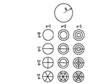
ここで、R:円板の半径、h:板厚、E:ヤング率、ρ:密度、σ:ポアソン比で、λnsは円板の振動様式によって決まる係数である。参考のため、先に示した公知文献からその振動様式を図5に、また、係数表を下記表1に示す。なお、図5において、nは直径方向の節の個数、sは周方向の節の個数である。
(Regarding the natural frequency of the bearing lid on the small gear side)
The small gear side bearing lid 3ca shown in FIG. 2 has a disk-like plate portion P. The plate thickness and diameter of the plate portion P differ depending on the gear device to be processed, but according to known literature (Watari thickness “mechanical vibration” Maruzen Co., Ltd., 1975), the natural frequency f of the disk is Can be obtained.
f = ω / 2π
However, ω = λns · a / R 2 , a = h (E / 12ρ (1-σ 2 )) 1/2
Here, R: disc radius, h: plate thickness, E: Young's modulus, ρ: density, σ: Poisson's ratio, and λns is a coefficient determined by the vibration mode of the disc. For reference, the vibration mode is shown in FIG. 5 and the coefficient table is shown in Table 1 below from the above-mentioned known documents. In FIG. 5, n is the number of nodes in the diameter direction, and s is the number of nodes in the circumferential direction.

一般の円板では固有振動数は無限にある。すなわち、λnsは無限に求めることができるが、前述の小歯車側の軸受ふたでは最小の固有振動数が共振周波数の範囲に入らないことが必要である。前記表1から最小の固有振動数とは、n=0、s=1よりλns=10.17として求めることができる。 In a general disk, the natural frequency is infinite. That is, λns can be obtained infinitely, but it is necessary that the minimum natural frequency does not fall within the resonance frequency range in the above-described bearing lid on the small gear side. From Table 1, the minimum natural frequency can be determined as λns = 10.17 from n = 0 and s = 1.
(共振周波数を変更する方法について)
先に説明した円板の固有振動数を求める関係式から、半径が決まった場合の前記軸受ふたの固有振動数を変更するには、(1)板厚(前述の円板の固有振動数を求める式中のh)を変更する、(2)板部の物性(E、ρ)を変更する手段が考えられる。
(How to change the resonance frequency)
In order to change the natural frequency of the bearing lid when the radius is determined from the relational expression for obtaining the natural frequency of the disc described above, (1) plate thickness (the natural frequency of the aforementioned disc is A means for changing (2) physical properties (E, ρ) of the plate portion can be considered.
このうち、(2)の板部の物性を変更する場合には、材質を変更することになるが、軸受ふたは鉄道車両用部品を構成する部品であることから、強度等の信頼性を考慮すると、従来から使用している材質を変更することは容易ではない。そのため、経験的に用いられている手段として、(3)軸受ふたの板部の剛性を変更する手段が考えられる。 Of these, when changing the physical properties of the plate part of (2), the material will be changed, but since the bearing lid is a part that constitutes a railway vehicle part, reliability such as strength is considered. Then, it is not easy to change the material used conventionally. Therefore, as means used empirically, (3) means for changing the rigidity of the plate portion of the bearing lid can be considered.
この手段を実際に適用するためには、(1)に示した板厚を変更するだけではなく、(3’)部分的に板厚を変更し、板部の剛性を変更することが考えられる。
ところで、前記軸受ふたの固有振動数を変更する際には、その固有振動数を上げる場合と、下げる場合が考えられるが、本発明の場合、固有振動数を下げると、(a)車両走行速度が遅い場合の噛み合い周波数に一致し、共振する可能性がある。(b)車両最高速度に達する過度的な速度にて大歯車と小歯車の噛み合い周波数と一致し、共振する可能性がある。(c)強度上の問題が発生する恐れがある。などの問題点がある。
In order to actually apply this means, it is possible not only to change the plate thickness shown in (1), but also to change the plate thickness (3 ′) by partially changing the plate thickness. .
By the way, when changing the natural frequency of the bearing lid, there are cases where the natural frequency is increased or decreased. In the present invention, when the natural frequency is decreased, (a) vehicle travel speed May coincide with the meshing frequency in the case of slow, and may resonate. (B) At an excessive speed that reaches the maximum vehicle speed, the meshing frequency of the large gear and the small gear may coincide with that of the small gear and may resonate. (C) There is a possibility that a problem in strength may occur. There are problems such as.
従って、軸受ふたに生じる固有振動数の変更には、固有振動数を大きくすることが望ましく、そのためには板厚を厚くする等して板部の剛性を高める必要がある。これが第3の本発明の鉄道車両用歯車装置である。 Therefore, it is desirable to increase the natural frequency in order to change the natural frequency generated in the bearing lid. For this purpose, it is necessary to increase the rigidity of the plate part by increasing the plate thickness. This is the railway vehicle gear device according to the third aspect of the present invention.
しかしながら、その際、単純に板部の板厚を厚くすると、軸受ふたの重量、さらには当該軸受ふたを取り付けた駆動装置の重量が増加し、近年、要求されている車両部品の軽量化に反することになってしまうことから、軸受ふたの板部の板厚を部分的に厚くする、板部に突出部を形成する、または、板部に補強リブを設けることで前記板部の剛性を部分的に上げることがより望ましい。これが第4及び第5の本発明の鉄道車両用歯車装置である。 However, if the plate thickness of the plate portion is simply increased at that time, the weight of the bearing lid and further the weight of the drive device to which the bearing lid is attached increases, which is contrary to the demanded weight reduction of vehicle parts in recent years. As a result, the plate thickness of the plate portion of the bearing lid is partially increased, the projection portion is formed on the plate portion, or the reinforcing rib is provided on the plate portion to partially increase the rigidity of the plate portion. It is more desirable to raise it. This is the gear device for railway vehicles of the fourth and fifth aspects of the present invention.
なお、この板厚を厚くする、または、剛性を上げる部分は、軸受ふたの板部であれば、外側すなわち箱表面側、或いは、内側すなわち箱内面側のいずれでも良いことは言うまでもない。 Needless to say, the portion that increases the thickness or increases the rigidity may be on the outside, ie, the box surface side, or on the inside, ie, the box inner surface side, as long as it is a plate portion of the bearing lid.
上記の本発明に係る鉄道車両用歯車装置を搭載した鉄道車両用台車にあっては、歯車装置の基本構成の変更や大幅な重量増加を伴うことなく、歯車箱に発生する振動や騒音を軽減できることから、必然的に台車の基本構成の変更や大幅な重量増加を伴わずに振動や騒音を軽減できるようになる。 In a railway vehicle bogie equipped with the above-described railway vehicle gear device according to the present invention, vibration and noise generated in the gear box are reduced without changing the basic configuration of the gear device and significantly increasing the weight. As a result, it is inevitably possible to reduce vibrations and noise without changing the basic structure of the carriage or significantly increasing the weight.
本発明によれば、鉄道車両用歯車装置の基本構成の変更や大幅な重量増加を伴うことなく、その歯車箱の振動、さらにはこの振動によって生じる騒音を可及的に小さくできるので、台車の基本構成の変更や大幅な重量増加を伴わずに台車の振動や騒音が防止され、更なる鉄道車両乗り心地の向上や騒音環境問題に対して大きな効果を奏する。 According to the present invention, the vibration of the gear box and the noise caused by the vibration can be reduced as much as possible without changing the basic configuration of the gear device for railway vehicles and the significant increase in weight. The vibration and noise of the bogie are prevented without changing the basic configuration and a significant increase in weight, and it has a great effect on further improving the riding comfort of the railway vehicle and noise environment problems.
以下、本発明の鉄道車両用歯車装置を実施するための形態について図6〜図10を用いて説明する。なお、以下の説明において、軸受ふたとは、小歯車側の軸受ふたを言うものとする。 Hereinafter, the form for implementing the gear apparatus for railway vehicles of this invention is demonstrated using FIGS. 6-10. In the following description, the bearing lid refers to a bearing lid on the small gear side.
図6〜図10は本発明の鉄道車両用歯車装置の特徴である軸受ふたを説明する図で、図6に示した例は、軸受ふた3caにおける板部Pの全体の板厚tを、図6に想像線で示した従来の軸受ふた3caにおける板部Pの全体の板厚t1よりも厚くすることで、板部Pの剛性を従来よりも高くしたものである。 6 to 10 are views for explaining a bearing lid, which is a feature of the railway vehicle gear device of the present invention. In the example shown in FIG. 6, the overall thickness t of the plate portion P of the bearing lid 3ca is illustrated. The rigidity of the plate portion P is made higher than that of the prior art by making it thicker than the overall plate thickness t1 of the plate portion P in the conventional bearing lid 3ca shown by an imaginary line in FIG.
また、図7に示した例は、軸受ふた3caにおける板部Pの外側中央部分に、縦断面が平板状の突出部Paを形成したもの、図8に示した例は、軸受ふた3caにおける板部Pの外側全域に、縦断面が凸湾曲状の突出部Pbを形成したものであり、これらの突出部Pa,Pbにより板部Pの剛性を従来よりも高くしている。なお、突出部Pbの大きさは板部Pの外側中央部分に形成してもよく、必要に応じて選択すればよい。
Further, in the example shown in FIG. 7, a projection part Pa having a longitudinal cross-section is formed at the outer central portion of the plate portion P in the bearing
また、図9に示した例は、軸受ふた3caにおける板部Pの外側に側面視十字状の補強リブPcを設けたもので、この補強リブPcにより板部Pの剛性を従来よりも高くしている。この補強リブPcの形状は、図9に示したような側面視十字状のものに限るものではなく、図10に示したような形状の補強リブでも良い。
Further, in the example shown in FIG. 9, a reinforcing rib Pc having a cross shape in a side view is provided on the outer side of the plate portion P in the bearing
なお、前記板厚t、突出部Pa,Pbや補強リブPcの厚みは、図2に示した従来の軸受ふた3caにおける取り付け面からの高さHに依存するものではない。また、環境問題を考慮した鉄道高速化には、車両の軽量化が一つの手段であるため、その観点から、軸受ふたの材質は鉄に限らず、アルミニウム合金などでも良い。 The plate thickness t, the protrusions Pa and Pb, and the thickness of the reinforcing rib Pc do not depend on the height H from the mounting surface of the conventional bearing lid 3ca shown in FIG. Further, since the reduction of the vehicle weight is one means for increasing the speed of the railway in consideration of environmental problems, the material of the bearing lid is not limited to iron, and an aluminum alloy may be used.
以上説明した本発明に係る歯車装置では、歯車装置の基本構成を変更することなく、また、重量を可及的に増加することなく、歯車箱に発生する振動や騒音を軽減できることから、台車の振動や騒音軽減を、台車の基本構成を変更することなく、また、大幅に重量を増加することなく行える。 In the gear device according to the present invention described above, the vibration and noise generated in the gear box can be reduced without changing the basic configuration of the gear device and without increasing the weight as much as possible. Vibration and noise can be reduced without changing the basic structure of the carriage and without significantly increasing the weight.
以下、本発明の効果を確認するために、前述の回転試験を行って図3の結果を得たものと同型の歯車装置を用いた加振試験を実施した。加振試験は、例えば公知文献である「モード解析ハンドブック」(モード解析ハンドブック編集委員会編、コロナ社、2000年)に示されているような一般的な方法にて行った。図11にその説明図を示す。 Hereinafter, in order to confirm the effect of the present invention, an excitation test was performed using the same type of gear device as that obtained by performing the above-described rotation test and obtaining the result of FIG. The vibration test was performed by a general method as shown in, for example, “Mode Analysis Handbook” (edited by the Mode Analysis Handbook Editorial Committee, Corona, 2000), which is a publicly known document. FIG. 11 shows an explanatory diagram thereof.
対象構造物6の加速度評価点には予め加速度計7を取り付けておき、力変換器8a付のハンマ8で打撃することによって対象構造物6にインパルスを与え、同時に加速度計7の出力を得る。そして、このハンマ8の加振力と対象構造物6の振動加速度からFFT(高速フーリエ変換)解析器9を通して周波数応答関数10あるいは伝達関数を求め、対象構造物6の固有振動数、さらにはFFT解析器9の出力からモード変形図等を出力する。ここに、ハンマが対象構造物に与えるインパルスは広帯域の周波数成分を有するため、歯車箱の周波数応答を評価するには十分である。
An
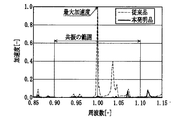
従来の軸受ふたと本発明の軸受ふたを取り付けた歯車箱を用意し、前述の加振試験方法に沿って加振試験を行い、軸受ふたを対象とした加速度応答を測定した結果を示す。ここで、歯車箱は加振試験に最も影響を及ぼさないと思われる点(孔部)にてワイヤで吊り下げ、大歯車側の軸受ふた取り付け部をインパクトハンマで加振し、軸受ふた中心位置の加速度応答を測定した。 A gear box equipped with a conventional bearing lid and the bearing lid of the present invention is prepared, an excitation test is performed according to the above-described excitation test method, and an acceleration response is measured for the bearing lid. Here, the gear box is hung with a wire at the point (hole) that seems to have the least influence on the vibration test, and the bearing lid mounting part on the large gear side is vibrated with an impact hammer, and the center position of the bearing lid The acceleration response of was measured.
加振試験の結果を図12に示すが、本発明品を使用した場合(実線)には、従来品を使用した場合(破線)に最大加速度となった周波数の前後10%の範囲の、共振周波数域での加速度を大幅に低減することができた。そして、従来品を使用した場合に最大加速度となった周波数では、加速度はその1.2%となっていた。 The result of the vibration test is shown in FIG. 12. When the product of the present invention is used (solid line), the resonance is within the range of 10% before and after the frequency at which the maximum acceleration is obtained when the conventional product is used (dashed line). The acceleration in the frequency range could be greatly reduced. The acceleration was 1.2% at the frequency at which the maximum acceleration was obtained when the conventional product was used.
本発明は上記の例に限らず、各請求項に記載された技術的思想の範囲内で、適宜実施の形態を変更しても良いことは、言うまでもない。 It goes without saying that the present invention is not limited to the above-described examples, and the embodiment may be appropriately changed within the scope of the technical idea described in each claim.
以上の本発明は、鉄道車両用の歯車装置に限らず、どのような歯車装置にも適用できる。 The present invention described above can be applied to any gear device, not limited to a gear device for a railway vehicle.
3 歯車装置
3aa 小歯車
3b 大歯車
3c 歯車箱
3ca 軸受ふた
P 板部
Pa、Pb 突出部
Pc 補強リブ
3 gear device 3aa
Claims (6)
小歯車側の軸受ふたの固有振動数が、当該鉄道車両の最高車両速度に対応する大歯車と小歯車との噛み合い周波数に一致しないように、前記軸受ふたを構成したことを特徴とする鉄道車両用歯車装置。 In a railway vehicle gear unit,
A railway vehicle characterized in that the bearing lid is configured so that the natural frequency of the bearing lid on the small gear side does not coincide with the meshing frequency of the large gear and the small gear corresponding to the maximum vehicle speed of the railway vehicle. Gear device.
前記板部の剛性を高めた構造であることを特徴とする請求項2に記載の鉄道車両用歯車装置。 The bearing lid includes a disk-shaped plate portion, and a fixed portion for attaching to the gear box of the gear device on the outer peripheral portion of the plate portion,
The gear device for a railway vehicle according to claim 2, wherein the rigidity of the plate portion is increased.
A railcar bogie comprising the railcar gear device according to any one of claims 1 to 6.
Priority Applications (1)
| Application Number | Priority Date | Filing Date | Title |
|---|---|---|---|
| JP2004149411A JP2005331027A (en) | 2004-05-19 | 2004-05-19 | Railway vehicle gear device and railway vehicle carriage |
Applications Claiming Priority (1)
| Application Number | Priority Date | Filing Date | Title |
|---|---|---|---|
| JP2004149411A JP2005331027A (en) | 2004-05-19 | 2004-05-19 | Railway vehicle gear device and railway vehicle carriage |
Publications (1)
| Publication Number | Publication Date |
|---|---|
| JP2005331027A true JP2005331027A (en) | 2005-12-02 |
Family
ID=35485830
Family Applications (1)
| Application Number | Title | Priority Date | Filing Date |
|---|---|---|---|
| JP2004149411A Pending JP2005331027A (en) | 2004-05-19 | 2004-05-19 | Railway vehicle gear device and railway vehicle carriage |
Country Status (1)
| Country | Link |
|---|---|
| JP (1) | JP2005331027A (en) |
Cited By (3)
| Publication number | Priority date | Publication date | Assignee | Title |
|---|---|---|---|---|
| JP2007269078A (en) * | 2006-03-30 | 2007-10-18 | Sumitomo Metal Ind Ltd | Railway vehicle gear device and railway vehicle carriage |
| CN109505870A (en) * | 2017-09-15 | 2019-03-22 | 米巴烧结奥地利有限公司 | Bearing cap |
| WO2023284269A1 (en) * | 2021-07-14 | 2023-01-19 | 中车青岛四方机车车辆股份有限公司 | Gearbox, bogie, and railway vehicle |
Citations (7)
| Publication number | Priority date | Publication date | Assignee | Title |
|---|---|---|---|---|
| JPS6325215Y2 (en) * | 1982-12-09 | 1988-07-11 | ||
| JPS63141355U (en) * | 1987-03-06 | 1988-09-19 | ||
| JPH02203060A (en) * | 1989-01-31 | 1990-08-13 | Mazda Motor Corp | Transmission case for automobile |
| JP2001213183A (en) * | 2000-01-31 | 2001-08-07 | Nissan Diesel Motor Co Ltd | Noise damping structure of transmission case |
| JP2001336616A (en) * | 2000-05-26 | 2001-12-07 | Sumitomo Metal Ind Ltd | Gears for railway vehicles |
| JP2002054723A (en) * | 2000-08-11 | 2002-02-20 | Aisin Aw Co Ltd | Automatic transmission case |
| JP2002161970A (en) * | 2000-11-27 | 2002-06-07 | Nissan Motor Co Ltd | Gear device shaft support structure |
-
2004
- 2004-05-19 JP JP2004149411A patent/JP2005331027A/en active Pending
Patent Citations (7)
| Publication number | Priority date | Publication date | Assignee | Title |
|---|---|---|---|---|
| JPS6325215Y2 (en) * | 1982-12-09 | 1988-07-11 | ||
| JPS63141355U (en) * | 1987-03-06 | 1988-09-19 | ||
| JPH02203060A (en) * | 1989-01-31 | 1990-08-13 | Mazda Motor Corp | Transmission case for automobile |
| JP2001213183A (en) * | 2000-01-31 | 2001-08-07 | Nissan Diesel Motor Co Ltd | Noise damping structure of transmission case |
| JP2001336616A (en) * | 2000-05-26 | 2001-12-07 | Sumitomo Metal Ind Ltd | Gears for railway vehicles |
| JP2002054723A (en) * | 2000-08-11 | 2002-02-20 | Aisin Aw Co Ltd | Automatic transmission case |
| JP2002161970A (en) * | 2000-11-27 | 2002-06-07 | Nissan Motor Co Ltd | Gear device shaft support structure |
Cited By (4)
| Publication number | Priority date | Publication date | Assignee | Title |
|---|---|---|---|---|
| JP2007269078A (en) * | 2006-03-30 | 2007-10-18 | Sumitomo Metal Ind Ltd | Railway vehicle gear device and railway vehicle carriage |
| CN109505870A (en) * | 2017-09-15 | 2019-03-22 | 米巴烧结奥地利有限公司 | Bearing cap |
| CN109505870B (en) * | 2017-09-15 | 2022-11-25 | 米巴烧结奥地利有限公司 | Bearing cap |
| WO2023284269A1 (en) * | 2021-07-14 | 2023-01-19 | 中车青岛四方机车车辆股份有限公司 | Gearbox, bogie, and railway vehicle |
Similar Documents
| Publication | Publication Date | Title |
|---|---|---|
| CN102472359B (en) | Vibration reducing device | |
| JP5244915B2 (en) | Drive shaft with array tuned absorber | |
| JP2009090921A (en) | In-wheel motor | |
| CN101547823A (en) | Steering wheel with reduced vibration transmission | |
| JP6237063B2 (en) | Railway vehicle gear device and railway vehicle carriage | |
| JP6568739B2 (en) | On-board equipment for railway vehicles | |
| JP2006001464A (en) | Railway vehicle gear device and railway vehicle carriage | |
| JP2000052979A (en) | Truck for monorail vehicle | |
| JP4882453B2 (en) | Railway vehicle gear device and railway vehicle carriage | |
| JP4573756B2 (en) | Anti-vibration device for vehicle | |
| JP4844095B2 (en) | Vibration transmissibility reduction device | |
| CN101082360B (en) | Damping component | |
| JP2018044561A (en) | Power transmission device using gear and gear member | |
| JPH09123770A (en) | Engine mount system | |
| JP4327158B2 (en) | Sheet metal drive plate | |
| CN118541553A (en) | Torsional vibration damper | |
| JP2004322898A (en) | Car wheels | |
| JPH09310751A (en) | Gears for railway vehicles | |
| JPH0544660U (en) | Vehicle Propeller Shaft | |
| Biswas | An Approach to Minimization of Drive Train Noise Through Redesign of Engine Mounts | |
| JPH11270627A (en) | Drive shaft for vehicles | |
| JP2025110801A (en) | Support structure for vehicle differential mechanism | |
| CN109982913B (en) | rail vehicle | |
| JP2010071447A (en) | Vehicle body structure | |
| JP2000158902A (en) | Tire wheel |
Legal Events
| Date | Code | Title | Description |
|---|---|---|---|
| A621 | Written request for application examination |
Free format text: JAPANESE INTERMEDIATE CODE: A621 Effective date: 20060601 |
|
| A977 | Report on retrieval |
Free format text: JAPANESE INTERMEDIATE CODE: A971007 Effective date: 20090716 |
|
| A131 | Notification of reasons for refusal |
Free format text: JAPANESE INTERMEDIATE CODE: A131 Effective date: 20090728 |
|
| A521 | Written amendment |
Free format text: JAPANESE INTERMEDIATE CODE: A523 Effective date: 20090928 |
|
| A131 | Notification of reasons for refusal |
Free format text: JAPANESE INTERMEDIATE CODE: A131 Effective date: 20100629 |
|
| A521 | Written amendment |
Free format text: JAPANESE INTERMEDIATE CODE: A523 Effective date: 20100830 |
|
| A02 | Decision of refusal |
Free format text: JAPANESE INTERMEDIATE CODE: A02 Effective date: 20110208 |