JP2005337635A - Cooling equipment - Google Patents
Cooling equipment Download PDFInfo
- Publication number
- JP2005337635A JP2005337635A JP2004159636A JP2004159636A JP2005337635A JP 2005337635 A JP2005337635 A JP 2005337635A JP 2004159636 A JP2004159636 A JP 2004159636A JP 2004159636 A JP2004159636 A JP 2004159636A JP 2005337635 A JP2005337635 A JP 2005337635A
- Authority
- JP
- Japan
- Prior art keywords
- cooling
- temperature
- quick freezing
- cooling device
- refrigerator
- Prior art date
- Legal status (The legal status is an assumption and is not a legal conclusion. Google has not performed a legal analysis and makes no representation as to the accuracy of the status listed.)
- Withdrawn
Links
Images





Classifications
-
- F—MECHANICAL ENGINEERING; LIGHTING; HEATING; WEAPONS; BLASTING
- F25—REFRIGERATION OR COOLING; COMBINED HEATING AND REFRIGERATION SYSTEMS; HEAT PUMP SYSTEMS; MANUFACTURE OR STORAGE OF ICE; LIQUEFACTION SOLIDIFICATION OF GASES
- F25B—REFRIGERATION MACHINES, PLANTS OR SYSTEMS; COMBINED HEATING AND REFRIGERATION SYSTEMS; HEAT PUMP SYSTEMS
- F25B9/00—Compression machines, plants or systems, in which the refrigerant is air or other gas of low boiling point
- F25B9/14—Compression machines, plants or systems, in which the refrigerant is air or other gas of low boiling point characterised by the cycle used, e.g. Stirling cycle
-
- F—MECHANICAL ENGINEERING; LIGHTING; HEATING; WEAPONS; BLASTING
- F25—REFRIGERATION OR COOLING; COMBINED HEATING AND REFRIGERATION SYSTEMS; HEAT PUMP SYSTEMS; MANUFACTURE OR STORAGE OF ICE; LIQUEFACTION SOLIDIFICATION OF GASES
- F25D—REFRIGERATORS; COLD ROOMS; ICE-BOXES; COOLING OR FREEZING APPARATUS NOT OTHERWISE PROVIDED FOR
- F25D2317/00—Details or arrangements for circulating cooling fluids; Details or arrangements for circulating gas, e.g. air, within refrigerated spaces, not provided for in other groups of this subclass
- F25D2317/06—Details or arrangements for circulating cooling fluids; Details or arrangements for circulating gas, e.g. air, within refrigerated spaces, not provided for in other groups of this subclass with forced air circulation
- F25D2317/066—Details or arrangements for circulating cooling fluids; Details or arrangements for circulating gas, e.g. air, within refrigerated spaces, not provided for in other groups of this subclass with forced air circulation characterised by the air supply
- F25D2317/0665—Details or arrangements for circulating cooling fluids; Details or arrangements for circulating gas, e.g. air, within refrigerated spaces, not provided for in other groups of this subclass with forced air circulation characterised by the air supply from the top
-
- F—MECHANICAL ENGINEERING; LIGHTING; HEATING; WEAPONS; BLASTING
- F25—REFRIGERATION OR COOLING; COMBINED HEATING AND REFRIGERATION SYSTEMS; HEAT PUMP SYSTEMS; MANUFACTURE OR STORAGE OF ICE; LIQUEFACTION SOLIDIFICATION OF GASES
- F25D—REFRIGERATORS; COLD ROOMS; ICE-BOXES; COOLING OR FREEZING APPARATUS NOT OTHERWISE PROVIDED FOR
- F25D2317/00—Details or arrangements for circulating cooling fluids; Details or arrangements for circulating gas, e.g. air, within refrigerated spaces, not provided for in other groups of this subclass
- F25D2317/06—Details or arrangements for circulating cooling fluids; Details or arrangements for circulating gas, e.g. air, within refrigerated spaces, not provided for in other groups of this subclass with forced air circulation
- F25D2317/068—Details or arrangements for circulating cooling fluids; Details or arrangements for circulating gas, e.g. air, within refrigerated spaces, not provided for in other groups of this subclass with forced air circulation characterised by the fans
- F25D2317/0682—Two or more fans
-
- F—MECHANICAL ENGINEERING; LIGHTING; HEATING; WEAPONS; BLASTING
- F25—REFRIGERATION OR COOLING; COMBINED HEATING AND REFRIGERATION SYSTEMS; HEAT PUMP SYSTEMS; MANUFACTURE OR STORAGE OF ICE; LIQUEFACTION SOLIDIFICATION OF GASES
- F25D—REFRIGERATORS; COLD ROOMS; ICE-BOXES; COOLING OR FREEZING APPARATUS NOT OTHERWISE PROVIDED FOR
- F25D2400/00—General features of, or devices for refrigerators, cold rooms, ice-boxes, or for cooling or freezing apparatus not covered by any other subclass
- F25D2400/04—Refrigerators with a horizontal mullion
-
- F—MECHANICAL ENGINEERING; LIGHTING; HEATING; WEAPONS; BLASTING
- F25—REFRIGERATION OR COOLING; COMBINED HEATING AND REFRIGERATION SYSTEMS; HEAT PUMP SYSTEMS; MANUFACTURE OR STORAGE OF ICE; LIQUEFACTION SOLIDIFICATION OF GASES
- F25D—REFRIGERATORS; COLD ROOMS; ICE-BOXES; COOLING OR FREEZING APPARATUS NOT OTHERWISE PROVIDED FOR
- F25D2400/00—General features of, or devices for refrigerators, cold rooms, ice-boxes, or for cooling or freezing apparatus not covered by any other subclass
- F25D2400/30—Quick freezing
-
- F—MECHANICAL ENGINEERING; LIGHTING; HEATING; WEAPONS; BLASTING
- F25—REFRIGERATION OR COOLING; COMBINED HEATING AND REFRIGERATION SYSTEMS; HEAT PUMP SYSTEMS; MANUFACTURE OR STORAGE OF ICE; LIQUEFACTION SOLIDIFICATION OF GASES
- F25D—REFRIGERATORS; COLD ROOMS; ICE-BOXES; COOLING OR FREEZING APPARATUS NOT OTHERWISE PROVIDED FOR
- F25D2700/00—Means for sensing or measuring; Sensors therefor
- F25D2700/02—Sensors detecting door opening
Landscapes
- Devices That Are Associated With Refrigeration Equipment (AREA)
- Cold Air Circulating Systems And Constructional Details In Refrigerators (AREA)
Abstract
【課題】 冷凍対象物を急速に冷凍することができる低消費電力の冷却機器を提供する。
【解決手段】 この冷却機器では、予冷スイッチ42がオンされたことに応じてスターリング冷凍機11の冷却能力を高くするとともに冷却ファン24をオフさせて低温側蒸発器15の温度Tcを通常よりも低下させ、急速冷凍室ドア6が開けられた後に閉じられたことに応じて冷却ファン24および急速冷却ファン23をオンさせる。したがって、冷凍対象物を急速に冷凍することができる。
【選択図】 図3PROBLEM TO BE SOLVED: To provide a cooling device with low power consumption capable of rapidly freezing an object to be frozen.
In this cooling device, the cooling capacity of the Stirling refrigerator 11 is increased in response to the precooling switch 42 being turned on, and the cooling fan 24 is turned off so that the temperature Tc of the low temperature side evaporator 15 is made higher than usual. The cooling fan 24 and the quick cooling fan 23 are turned on when the quick freezer compartment door 6 is closed and then closed. Therefore, the object to be frozen can be rapidly frozen.
[Selection] Figure 3
Description
この発明は冷却ファンにより冷却される冷凍室を備えた冷却機器に関し、より好ましくは、スターリング冷凍機の冷却部から2次冷媒を介して搬送される冷熱によって冷却される冷凍室を備えた冷却機器に関する。 The present invention relates to a cooling device including a freezing chamber cooled by a cooling fan, and more preferably, a cooling device including a freezing chamber cooled by cold heat conveyed from a cooling unit of a Stirling refrigerator via a secondary refrigerant. About.
近年、フロンガスの地球環境への悪影響が指摘されており、フロンガスを使用しない冷却機器としてスターリング冷凍機を搭載したものが注目されている。この冷却機器では、スターリング冷凍機のコールドヘッドの冷熱が低温側蒸発器に伝達され、低温側蒸発器の冷気が冷却ファンによって冷凍室に供給される(たとえば特許文献1参照)。
ところで、冷凍・解凍による冷凍対象物の品質劣化を抑制するためには、冷凍時に冷凍対象物の細胞内に発生する氷を小さくし、氷による細胞の破壊を抑制する必要がある。この氷の大きさは、冷凍対象物が最大氷結晶生成温度帯を通過する時間に比例して大きくなる。したがって、冷凍室の温度を低くして冷凍対象物を急速に冷凍する必要がある。その一方、冷凍室の温度を常時低くすると、冷却機器の消費電力が増大する。 By the way, in order to suppress the quality deterioration of the frozen object due to freezing / thawing, it is necessary to reduce the ice generated in the cells of the frozen object during freezing and to suppress the destruction of the cells by the ice. The size of the ice increases in proportion to the time during which the object to be frozen passes through the maximum ice crystal generation temperature zone. Therefore, it is necessary to rapidly freeze the object to be frozen by lowering the temperature of the freezer. On the other hand, if the temperature of the freezer compartment is constantly lowered, the power consumption of the cooling device increases.
それゆえに、この発明の主たる目的は、冷凍対象物を急速に冷凍することができる低消費電力の冷却機器を提供することである。 Therefore, a main object of the present invention is to provide a cooling device with low power consumption that can rapidly freeze an object to be frozen.
この発明に係る冷却機器は、冷凍室を備えた冷却機器であって、冷凍機によって冷却される蒸発器と、蒸発器の冷気を冷凍室内に供給する冷却ファンと、急速冷凍に係わる信号の入力に基づいて、冷却ファンを停止させて冷凍機を駆動させる予冷モード運転を実行する制御部とを備えたものである。本発明は、現在市販されている冷凍冷蔵庫に適用しても良いが、スターリング冷凍機の冷却部から低温側蒸発器に冷熱を搬送する2次冷媒循環回路を備えた冷却機器に適用するのがより好ましい。 The cooling device according to the present invention is a cooling device provided with a freezer compartment, an evaporator cooled by the refrigerator, a cooling fan for supplying the cooler of the evaporator into the freezer compartment, and input of signals relating to quick freezing And a control unit that executes a pre-cooling mode operation in which the cooling fan is stopped to drive the refrigerator. The present invention may be applied to a commercially available refrigerator-freezer, but may be applied to a cooling device having a secondary refrigerant circulation circuit that conveys cold heat from a cooling unit of a Stirling refrigerator to a low-temperature evaporator. More preferred.
この発明に係る冷却機器では、急速冷凍に係わる信号の入力に基づいて、冷却ファンを停止させて冷凍機を駆動させる予冷モード運転を実行する。したがって、冷凍対象物が最大氷結晶生成温度帯に突入するまでに蒸発器に蓄冷することができ、冷凍対象物が最大氷結晶生成温度帯を通過する時間を短縮することができる。また、急速冷凍に係わる信号の入力がない場合は、通常通り運転するので、消費電力の増大を抑制することができる。 In the cooling device according to the present invention, the pre-cooling mode operation is performed in which the cooling fan is stopped and the refrigerator is driven based on the input of a signal related to quick freezing. Therefore, it is possible to store in the evaporator before the frozen object enters the maximum ice crystal generation temperature zone, and to shorten the time for the frozen object to pass through the maximum ice crystal generation temperature zone. In addition, when there is no input of a signal related to quick freezing, since the operation is performed as usual, an increase in power consumption can be suppressed.
[実施の形態1]
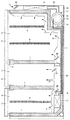
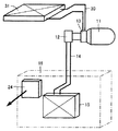
図1はこの発明の実施の形態1による冷却機器の構成を示す概略断面図であり、図2は冷却機器の配管構成図である。図1および図2において、この冷却機器は、食品保存用であり、断熱構造のハウジング1を備える。ハウジング1の内部は上下3段に仕切られており、上側から冷蔵室2、急速冷凍室3および冷凍室4が構成されている。冷蔵室2、急速冷凍室3および冷凍室4の正面側(図1では左側)の開口部には、それぞれ断熱性の冷蔵室ドア5、急速冷凍室ドア6および冷凍室ドア7が開閉自在に設けられている。ドア5〜7の各々の裏面には、対応の室の開口部をそれぞれ囲む形のドアパッキン8が装着されている。ハウジング1の内部には、収納する食品の種類に適合した棚9が適宜配置されている。
[Embodiment 1]
1 is a schematic cross-sectional view showing a configuration of a cooling device according to
ハウジング1の上背面の一角には機械室10が設けられており、機械室10にはスターリング冷凍機11が設置されている。ハウジング1の上面から背面、さらには下面にかけては、スターリング冷凍機11を中心要素とする冷却システムが配設されている。
A
スターリング冷凍機11には駆動により発生する冷熱を取出すコールドヘッド(図示せず)があり、そのコールドヘッドを覆うようにして低温側凝縮器12が取付けられている。また、冷凍室4の奥には、低温側蒸発器15が設置されている。低温側凝縮器12と低温側蒸発器15は低温側2次冷媒循環パイプ14を介して接続されており、両者によって2次冷媒循環回路が構成されている。2次冷媒循環回路には、CO2などの自然冷媒が封入されており、低温側蒸発器15および低温側凝縮器12間で冷熱の授受が行なわれる。
The Stirling
ハウジング1の内部には、低温側蒸発器15によって得られた冷気を冷蔵室2、急速冷凍室3および冷凍室4へ分配するためのダクト20が設けられている。ダクト20には、冷蔵室2、急速冷凍室3または冷凍室4に連通する冷気噴出口21が適所に設けられている。また、ダクト20内には、それぞれ冷蔵室2、急速冷凍室3および冷凍室4に冷気を強制的に送り出すための冷蔵ファン22、急速冷凍ファン23および冷却ファン24が設けられている。冷却ファン24および低温側蒸発器15は、低温側蒸発器室16内に設けられている。
Inside the
スターリング冷凍機11には駆動により発生する温熱を取出すウォームヘッド(図示せず)があり、そのウォームヘッドを覆うようにして高温側蒸発器13が取付けられている。また、ハウジング1の上面には、庫外環境に放熱を行なう高温側凝縮器31と送風ファン32が設けられている。高温側蒸発器13と高温側凝縮器31は高温側2次冷媒循環パイプ30を介して接続されており、両者によって高温側自然循環回路が構成されている。高温側自然循環回路には、水(水溶液を含む)あるいは炭化水素系の自然冷媒が密封されており、冷媒は高温側自然循環回路内を自然循環する。
The Stirling
次に、この冷却機器の動作について説明する。スターリング冷凍機11が駆動されると、コールドヘッドの温度が低下する。したがって、低温側凝縮器12は冷却され、その内部の冷媒が凝縮される。
Next, the operation of this cooling device will be described. When the Stirling
低温側凝縮器12で凝縮された2次冷媒は、低温側2次冷媒循環パイプ14を通って低温側蒸発器15に流れ込む。低温側蒸発器15に流れ込んだ2次冷媒は、低温側蒸発器15の外側を通過する気流の熱で蒸発し、低温側蒸発器15の表面温度を下げる。したがって、低温側蒸発器15を通り抜ける空気は冷気となり、ダクト20の冷気吹出口21から冷凍室4などに吹出し、冷凍室4などの温度を下げる。低温側蒸発器15で蒸発した2次冷媒は、低温側2次冷媒循環パイプ14を通って低温側凝縮器12に戻り、そこで熱を奪われて再び凝縮する。
The secondary refrigerant condensed in the low
一方、スターリング冷凍機11の駆動によって発生する温熱は、ウォームヘッドを介して高温側蒸発器13に放熱される。高温側蒸発器13内部は2次冷媒が蒸発することによる気化熱で温熱が奪われる。
On the other hand, the warm heat generated by driving the Stirling
高温側蒸発器13で蒸発した気相状態の2次冷媒は、高温側2次冷媒循環パイプ30を通って、上方に設けられた高温側凝縮器31に流れ込む。高温側凝縮器31に流れ込んだ2次冷媒は、送風ファン32によって庫外から高温側凝縮器31内に導入された気流により熱を奪われて凝縮する。高温側凝縮器31で凝縮した2次冷媒は高温側2次冷媒循環パイプ30を通って高温側蒸発器13に戻り、そこで熱を受け取って再び蒸発する。
The secondary refrigerant in a vapor phase evaporated by the high
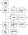
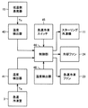
次に、この冷却機器の特徴となる急速冷凍方法について説明する。図3において、この冷却機器は、さらに、温度検出器40,41、予冷スイッチ42、ドア開閉状態検出器43、および制御部44を備える。温度検出器40は、低温側蒸発器15の温度Tcを検出し、検出した温度Tcを示す信号を制御部44に与える。温度検出器41は、急速冷凍室3内の温度Tqを検出し、検出した温度Tqを示す信号を制御部44に与える。
Next, a quick freezing method that is a feature of this cooling device will be described. In FIG. 3, the cooling device further includes
予冷スイッチ42は、たとえば急速冷凍室ドア6の外側表面に設けられ、冷却機器の使用者によってオンされると、予冷モードの開始を指示する信号を制御部44に与える。ドア開閉状態検出器43は、ドア開閉状態すなわち急速冷凍室ドア6が開けられているか閉じられているかを検出し、検出結果を示す信号を制御部44に与える。制御部44は、温度検出器40,41、予冷スイッチ42およびドア開閉状態検出器43からの信号に従って、スターリング冷凍機11、冷却ファン24および急速冷凍ファン23を制御する。
For example, the
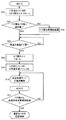
図4〜図8は、制御部44の制御動作を示すフローチャートである。ステップS1において、制御部44は、予冷スイッチ42がオンされるのを待機する。予冷スイッチ42がオンされると、ステップS2において予冷モードが開始される。予冷モードが開始されると、ステップS3において制御部44は、スターリング冷凍機11の冷却能力を通常よりも高いレベルに設定し、冷却ファン24をオフし、予冷タイマをスタートさせる。
4 to 8 are flowcharts showing the control operation of the
ステップS4において、予冷モードの温度制御が行われる。図6は、予冷モードの温度制御を示すフローチャートである。ステップS21において、制御部44は、温度検出器40によって検出された低温側蒸発器15の温度Tcが設定値に等しいか否かを判別し、Tcが設定値に等しい場合はステップS22に進み、Tcが設定値に等しくない場合はステップS23に進む。Tcの設定値を低い温度に設定するほど2次冷媒の蓄冷効果が大きくなり、冷凍対象物が最大氷結晶生成温度帯を通過する時間を短縮できる。しかし、Tcの設定値を低い温度にし過ぎると、2次冷媒が凍結するおそれがある。したがって、Tcの設定値は、2次冷媒が凍結しない温度に設定する必要がある。
In step S4, temperature control in the precooling mode is performed. FIG. 6 is a flowchart showing temperature control in the precooling mode. In step S21, the
ステップS22では、スターリング冷凍機11の冷却能力を維持し、冷却ファン24の状態(オフ状態)を維持し、ステップS5に進む。ステップS23では、Tcが設定値よりも高いか否かを判別し、Tcが設定値よりも高い場合はステップS24に進み、Tcが設定値よりも高くない場合はステップS25に進む。ステップS24では、スターリング冷凍機11の冷却能力を高くし、冷却ファン24をオフさせ、ステップS5に進む。ステップS25では、スターリング冷凍機11の冷却能力を維持または低くし、ステップS5に進む。このようにして、予冷モードでは、低温側蒸発器15の温度Tcが設定値よりも低くならないように制御される。
In step S22, the cooling capacity of the
図4に戻って、ステップS5において制御部44は、予冷タイマが所定時間1を計時したか否かを判別し、予冷タイマが所定時間1を計時していない場合はステップS7に進み、予冷タイマが所定時間1を計時している場合はステップS6に進む。
Returning to FIG. 4, in step S5, the
ステップS6では、予冷スイッチ42がオンされたにもかかわらず、急速冷凍室ドア6が開閉されなかった、すなわち急速冷凍室3に冷凍対象物が収納されなかったので、急速冷凍解除モードを実行する。図7は、急速冷凍解除モードを示すフローチャートである。図7において、急速冷凍解除モードでは、ステップS30においてスターリング冷凍機11の駆動状態を低下させ、冷却ファン24を制御状態にし、予冷タイマをリセットし、通常モードの温度制御に戻る。
In step S6, although the quick freezing
図4に戻って、ステップS7において制御部44は、予冷タイマが所定時間2(<所定時間1)を計時したか否かを判別し、予冷タイマが所定時間2を計時している場合はステップS8で予冷が完了したことをブザー、ランプなどで報知し、予冷タイマが所定時間2を計時していない場合はステップS9に進む。ステップS9において制御部44は、ドア開閉状態検出器43の出力信号に基づいて急速冷凍室ドア6が開けられているか否かを判別し、急速冷凍室ドア6が開けられていない場合はステップS4に戻り、急速冷凍室ドア6が開けられている場合は図5のステップS10に進む。
Returning to FIG. 4, in step S <b> 7, the
ステップS10では、予冷タイマをオフし、ドア開タイマをスタートする。ステップS11では、ドア開タイマ値が設定値よりも小さいか否かを判別し、ドア開タイマ値が設定値よりも小さくない場合はステップS12でドアが開いていることを冷却機器の使用者にたとえばブザー音により報知し、ドア開タイマ値が設定値よりも小さい場合はステップS13に進む。 In step S10, the pre-cooling timer is turned off and the door opening timer is started. In step S11, it is determined whether or not the door open timer value is smaller than the set value. If the door open timer value is not smaller than the set value, the cooling device user is informed that the door is open in step S12. For example, when a buzzer sound is notified and the door opening timer value is smaller than the set value, the process proceeds to step S13.
ステップS13において制御部44は、急速冷凍室3内に冷凍対象物が収容されて急速冷凍室ドア6が閉じられるのを待機する。急速冷凍ドア6が閉じられると、ステップS14においてドア閉タイマをスタートする。ステップS15において冷却ファン24および急速冷凍ファン23をオンし、ステップS16において急速冷凍モードの温度制御を実行する。
In step S <b> 13, the
図8は、急速冷凍モードの温度制御を示すフローチャートである。ステップS31において、制御部44は、急速冷凍室3の温度Tqが設定値に等しいか否かを判別し、Tqが設定値に等しい場合はステップS32に進み、Tqが設定値に等しくない場合はステップS33に進む。ステップS32では、スターリング冷凍機11の冷却能力を維持し、冷却ファン24および急速冷凍ファン23をオンし、ステップS17に進む。ステップS33では、Tqが設定値よりも高いか否かを判別し、Tqが設定値よりも高い場合はステップS34に進み、Tqが設定値よりも高くない場合はステップS35に進む。ステップS34では、スターリング冷凍機11の冷却能力を高くし、冷却ファン24および急速冷凍ファン23をオンし、ステップS17に進む。ステップS35では、スターリング冷凍機11の冷却能力を維持または低下させ、冷却ファン24をオフし、急速冷凍ファン23をオフしてステップS17に進む。このようにして、急速冷凍モードでは、急速冷凍室3の温度Tqが設定値に等しくなるように制御される。
FIG. 8 is a flowchart showing temperature control in the quick freezing mode. In step S31, the
図5に戻って、ステップS17において制御部44は、急速冷凍室ドア6が閉じられてから急速冷凍所定時間が経過したか否かを判別し、急速冷凍所定時間が経過していない場合はステップS16に戻り、急速冷凍所定時間が経過した場合は通常温度制御モードに戻る。
Returning to FIG. 5, in step S <b> 17, the
この実施の形態1では、予冷スイッチ42がオンされたことに応じてスターリング冷凍機11の冷却能力を高くするとともに冷却ファン24をオフさせて2次冷媒循環回路(特に2次冷媒)の温度を低下させて蓄冷し、急速冷凍室ドア6が開けられた後に閉じられたことに応じて冷却ファン24および急速冷凍ファン23をオンさせる。したがって、冷凍対象物を2次冷媒循環回路に蓄冷された冷力によって最大氷結晶生成温度帯を急速に通過させることができ、冷凍・解凍による冷凍対象物の品質低下を防止することができる。また、予冷スイッチ42がオンされたときのみスターリング冷凍機11の冷却能力を高めるので、消費電力の増大が小さくて済む。
In the first embodiment, the cooling capacity of the
なお、この実施の形態1では、予冷モードにおいて低温側蒸発器15の温度Tcが設定値になるようにスターリング冷凍機11および冷却ファン24を制御したが、温度検出器40によって2次冷媒循環回路の任意の部分の温度を検出し、その検出温度に基づいて制御しても良い。たとえば、スターリング冷凍機11のコールドヘッドの温度が設定値になるように制御しても良い。
In the first embodiment, the
また、この実施の形態1では、予冷スイッチ42がオンされたことに応じて予冷モードが開始されたが、予冷スイッチ42を除去し、急速冷凍室ドア6が開けられたことに応じて予冷モードを開始しても良い。さらに、急速冷凍室ドア6が開けられた後に閉じられても、冷凍対象物が急速冷凍室3に収容されなかったことを赤外線センサで検出して急速冷凍モードを中止するようにしてもよい。
In the first embodiment, the pre-cooling mode is started in response to the
[実施の形態2]
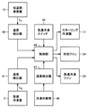
図9は、この発明の実施の形態2による冷却機器の急速冷凍モードに関連する部分の構成を示すブロック図であって、図3と対比される図である。図9を参照して、この冷却機器が図3の冷却機器と異なる点は、予冷スイッチ42およびドア開閉状態検出器43が除去され、急速冷凍スイッチ45および温度検出器46が設けられている点である。
[Embodiment 2]
FIG. 9 is a block diagram showing a configuration of a portion related to the quick refrigeration mode of the cooling device according to the second embodiment of the present invention, and is compared with FIG. Referring to FIG. 9, this cooling device is different from the cooling device of FIG. 3 in that the precooling
急速冷凍スイッチ45は、たとえば急速冷凍室ドア6の外側表面に設けられ、冷却機器の使用者によってオンされると、予冷モードの開始を指示する信号を制御部44に与える。温度検出器46は、冷却機器が設置されている雰囲気の温度を検出し、検出結果を示す信号を制御部44に与える。制御部44は、温度検出器40,41,46、急速冷凍スイッチ45からの信号に従って、スターリング冷凍機11、冷却ファン24および急速冷凍ファン23を制御する。
The quick freezing
図10および図11は、制御部44の制御動作を示すフローチャートである。この冷却機器では、急速冷凍スイッチ45のオン操作に前後して冷凍対象物が急速冷凍室3に収容される。ステップS41において、制御部44は、急速冷凍スイッチ45がオンされるのを待機する。急速冷凍スイッチ45がオンされると、ステップS42において予冷モードが開始される。予冷モードが開始されると、ステップS43において制御部44は、スターリング冷凍機11の冷却能力を通常よりも高いレベルに設定し、冷却ファン23をオフし、予冷タイマをスタートさせ、温度検出器46によって検出された設置雰囲気温度に基づいて予冷所定時間を設定する。制御部44は、たとえば、設置雰囲気温度が標準温度(たとえば20℃)よりも高い場合は予冷所定時間を長く補正し、設置雰囲気温度が標準温度よりも低い場合は予冷所定時間を短く補正する。
10 and 11 are flowcharts showing the control operation of the
ステップS44において、予冷モードの温度制御が行われる。図11は、予冷モードの温度制御を示すフローチャートである。ステップS51において、制御部44は、温度検出器40によって検出された低温側蒸発器15の温度Tcが設定値以下か否かを判別し、Tcが設定値以下の場合はステップS45に進み、Tcが設定値以下でない場合はステップS52に進む。Tcの設定値を低い温度に設定するほど2次冷媒の蓄冷効果が大きくなり、冷凍対象物が最大氷結晶生成温度帯を通過する時間を短縮できる。しかし、Tcの設定値を低い温度にし過ぎると、2次冷媒が凍結するおそれがある。したがって、Tcの設定値は、2次冷媒が凍結しない温度に設定する必要がある。
In step S44, temperature control in the precooling mode is performed. FIG. 11 is a flowchart showing temperature control in the precooling mode. In step S51, the
ステップS52では、予冷を開始してから経過した時間が予冷所定時間以上か否かを判別し、予冷所定時間以上の場合はステップS45に進み、予冷所定時間以上でない場合はステップS51に戻る。ここで、予冷所定時間は、標準量かつ標準温度の冷凍対象物を通常運転温度の急速冷凍室3にて最大氷結晶生成温度帯上限温度まで冷却する時間に設定されている。
In step S52, it is determined whether or not the time elapsed since the start of precooling is equal to or longer than the predetermined time for precooling. If the predetermined time is equal to or longer than the predetermined time for precooling, the process proceeds to step S45. Here, the pre-cooling predetermined time is set to a time for cooling the standard amount and standard temperature of the object to be frozen to the maximum ice crystal generation temperature zone upper limit temperature in the
ステップS45では、冷却ファン24および急速冷凍ファン23をオンさせ、ステップS46で急速冷凍モードを実行する。急速冷凍モードの温度制御は、図8で説明した通りである。ステップS47において制御部44は、急速冷凍スイッチ45がオンされてから所定時間が経過したか否かを判別し、所定時間が経過していない場合はステップS46に戻り、所定時間が経過した場合は通常温度制御モードに戻る。
In step S45, the cooling
この実施の形態2では、急速冷凍スイッチ45がオンされたことに応じてスターリング冷凍機11の冷却能力を高くするとともに冷却ファン24をオフさせて2次冷媒循環回路の温度を低下させて蓄冷し、所定時間経過後に冷却ファン24および急速冷凍ファン23をオンさせる。したがって、最大氷結晶生成温度帯上限温度近辺まで予冷した冷凍対象物を2次冷媒循環回路に蓄冷された冷力によって最大氷結晶生成温度帯を急速に通過させることができ、冷凍・解凍による冷凍対象物の品質低下を防止することができる。また、急速冷凍スイッチ45がオンされたときのみスターリング冷凍機11の冷却能力を高めるので、消費電力の増大を抑制することができる。
In the second embodiment, the cooling capacity of the
なお、この実施の形態2では、急速冷凍スイッチ45がオンされたことに応じて予冷モードが開始されたが、急速冷凍スイッチ45を除去し、急速冷凍室ドア6が開けられたことに応じて予冷モードを開始しても良い。
In the second embodiment, the precooling mode is started in response to the quick freezing
図12は、この実施の形態2の変更例を示すブロック図であって、図9と対比される図である。図12を参照して、この冷却機器が図9の冷却機器と異なる点は、温度検出器46が除去されている点である。図9の冷却機器では、ステップS43において冷却機器の設置雰囲気温度を温度検出器46によって検出し、その検出結果に基づいて予冷所定時間を設定した。しかし、急速冷凍室3の温度Tqが複数段階で切換可能にされている場合は、急速冷凍室3の温度Tqに従って予冷所定時間を変える必要がある。そこで、図12の冷却機器では、予冷モード開始時に温度検出器41によって検出された急速冷凍室3の温度Tqに基づき、ステップS43において予冷所定時間を設定する。制御部44は、たとえば、急速冷凍室3の温度Tqが標準温度(たとえば−18℃)よりも高い場合は予冷所定時間を長く補正し、急速冷凍室3の温度Tqが標準温度よりも低い場合は予冷所定時間を短く補正する。この変更例では、急速冷凍室3の温度Tqに応じて予冷所定時間を適切に設定することができる。なお、急速冷凍室3の温度Tqと冷却機器の設置雰囲気温度の両方に基づいて予冷所定時間を設定すればさらに好ましいことは言うまでもない。
FIG. 12 is a block diagram showing a modification of the second embodiment, and is a diagram contrasted with FIG. Referring to FIG. 12, this cooling device is different from the cooling device of FIG. 9 in that
また、予冷所定時間を設定する代わりに、2次冷媒が凍結しないよう予め定められた温度に2次冷媒が係わる温度(低温側凝縮器12の温度、低温側2次冷媒循環パイプの温度、低温側蒸発器15の温度)が到達することにより、急速冷凍モード運転に切換えるようにしてもよい。
Further, instead of setting a predetermined precooling time, the temperature at which the secondary refrigerant is related to a predetermined temperature so that the secondary refrigerant does not freeze (temperature of the low-
図13は、この実施の形態2の他の変更例を示すブロック図であって、図9と対比される図である。図13を参照して、この冷却機器が図9の冷却機器と異なる点は、温度検出器46が温度検出器47で置換されている点である。温度検出器47は、急速冷凍室3内に収容された冷凍対象物48の温度を検出する。図13の冷却機器では、ステップS43において予冷所定時間を設定せず、ステップS52において冷凍対象物48の温度が最大氷結晶生成温度帯上限に到達したか否かを判別し、最大氷結晶生成温度帯上限に到達していない場合はステップS51に戻り、最大氷結晶生成温度帯上限に到達した場合はステップS45に進む。この変更例では、冷凍対象物48の温度によって予冷モードから急速冷凍モードに切換えることができる。
FIG. 13 is a block diagram showing another modification of the second embodiment, and is a diagram contrasted with FIG. Referring to FIG. 13, this cooling device is different from the cooling device of FIG. 9 in that
今回開示された実施の形態はすべての点で例示であって制限的なものではないと考えられるべきである。本発明の範囲は上記した説明ではなくて特許請求の範囲によって示され、特許請求の範囲と均等の意味および範囲内でのすべての変更が含まれることが意図される。 The embodiment disclosed this time should be considered as illustrative in all points and not restrictive. The scope of the present invention is defined by the terms of the claims, rather than the description above, and is intended to include any modifications within the scope and meaning equivalent to the terms of the claims.
1 ハウジング、2 冷蔵室、3 急速冷凍室、4 冷凍室、5 冷蔵室ドア、6 急速冷凍室ドア、7 冷凍室ドア、8 ドアパッキン、9 棚、10 機械室、11 スターリング冷凍機、12 低温側凝縮器、14 低温側2次冷媒循環パイプ、15 低温側蒸発器、16 低温側蒸発器室、20 ダクト、21 冷気噴出口、22 冷蔵ファン、23 急速冷凍ファン、24 冷却ファン、30 高温側2次冷媒循環パイプ、31 高温側凝縮器、32 送風ファン、40,41,46,47 温度検出器、42 予冷スイッチ、43 ドア開閉状態検出器、44 制御部、45 急速冷凍スイッチ、48 冷凍対象物。
DESCRIPTION OF
Claims (10)
冷凍機によって冷却される蒸発器、
前記蒸発器の冷気を前記冷凍室内に供給する冷却ファン、および
急速冷凍に係わる信号の入力に基づいて、前記冷却ファンを停止させて前記冷凍機を駆動させる予冷モード運転を実行する制御部を備えた、冷却機器。 A cooling device with a freezer compartment,
Evaporator, cooled by refrigerator
A cooling fan for supplying cool air from the evaporator into the freezer compartment, and a control unit for executing a pre-cooling mode operation for stopping the cooling fan and driving the refrigerator based on input of a signal related to quick freezing Cooling equipment.
前記冷凍機の冷却部から2次冷媒を介して冷熱を受ける低温側蒸発器、
前記低温側蒸発器の冷気を前記冷凍室内に供給する冷却ファン、および
急速冷凍に係わる信号の入力に基づいて、前記冷却ファンを停止させて前記冷凍機を駆動させる予冷モード運転を実行する制御部を備えた、冷却機器。 A cooling device having a freezing room cooled by a freezer,
A low-temperature evaporator that receives cold from the cooling unit of the refrigerator via a secondary refrigerant;
A cooling fan that supplies cold air from the low-temperature side evaporator into the freezer compartment, and a control unit that executes a precooling mode operation that stops the cooling fan and drives the refrigerator based on input of a signal related to quick freezing With cooling equipment.
前記制御部は、前記ドア状態検出器の検出結果に基づき、前記冷凍室のドアが開けられて閉じられたことに応じて、前記予冷モード運転から急速冷凍モード運転に切換え、前記冷凍機の冷却能力を通常運転よりも高いレベルに設定するとともに前記冷却ファンを駆動させる、請求項1または請求項2に記載の冷却機器。 A door state detector for detecting an open / closed state of the freezer door;
Based on the detection result of the door state detector, the control unit switches from the precooling mode operation to the quick freezing mode operation in response to the opening of the freezer compartment being closed and cooling the refrigerator. The cooling device according to claim 1 or 2, wherein the cooling fan is driven while setting the capacity to a level higher than that of normal operation.
前記制御部は、前記温度検出器の検出結果に基づき、前記2次冷媒が凍結しないように前記冷凍機の冷却能力を制御する、請求項2または請求項3に記載の冷却機器。 A temperature detector for detecting a temperature related to the secondary refrigerant;
The cooling device according to claim 2 or 3, wherein the control unit controls the cooling capacity of the refrigerator so that the secondary refrigerant does not freeze based on a detection result of the temperature detector.
前記制御部は、前記急速冷凍に係わる信号の入力に基づいて、前記予冷モード運転を所定時間実行した後に、前記冷凍機の冷却能力を通常運転よりも高いレベルに設定するとともに前記冷却ファンを駆動させる急速冷凍モード運転を実行する、請求項1または請求項2に記載の冷却機器。 A quick freezing switch for inputting a signal related to the quick freezing,
The control unit sets the cooling capacity of the refrigerator to a level higher than that of normal operation and drives the cooling fan after executing the precooling mode operation for a predetermined time based on an input of a signal related to the quick freezing. The cooling device according to claim 1 or 2, wherein the quick freezing mode operation is executed.
前記所定時間は、前記温度検出器の検出結果に基づいて定められる、請求項6に記載の冷却機器。 A temperature detector for detecting an installation atmosphere temperature of the cooling device;
The cooling device according to claim 6, wherein the predetermined time is determined based on a detection result of the temperature detector.
前記所定時間は、前記予冷モード運転の開始時における前記温度検出器の検出結果に基づいて定められる、請求項6に記載の冷却機器。 A temperature detector for detecting the temperature of the freezer;
The cooling device according to claim 6, wherein the predetermined time is determined based on a detection result of the temperature detector at the start of the pre-cooling mode operation.
前記2次冷媒に係わる温度を検出する温度検出器を備え、
前記制御部は、前記急速冷凍に係わる信号の入力に基づいて前記予冷モード運転を実行し、前記温度検出器の検出結果に基づき、前記2次冷媒が凍結しないように予め定められた温度に前記2次冷媒に係わる温度が到達した後に、前記冷凍機の冷却能力を通常運転よりも高いレベルに設定するとともに前記冷却ファンを駆動させる急速冷凍モード運転を実行する、請求項2に記載の冷却機器。 A quick freezing switch for inputting a signal related to the quick freezing, and a temperature detector for detecting a temperature related to the secondary refrigerant,
The control unit performs the pre-cooling mode operation based on an input of a signal related to the quick freezing, and based on a detection result of the temperature detector, the control unit is set to a predetermined temperature so that the secondary refrigerant does not freeze. The cooling device according to claim 2, wherein after the temperature related to the secondary refrigerant reaches, the cooling capacity of the refrigerator is set to a level higher than that of a normal operation and the quick freezing mode operation for driving the cooling fan is executed. .
前記制御部は、前記急速冷凍に係わる信号の入力に基づいて前記予冷モード運転を実行し、前記温度検出器の検出結果に基づき、前記冷凍対象物の温度が最大氷結晶生成温度帯上限に到達したことに応じて、前記冷凍機の冷却能力を通常運転よりも高いレベルに設定するとともに前記冷却ファンを駆動させる急速冷凍モード運転を実行する、請求項1または請求項2に記載の冷却機器。 It has a temperature detector that detects the temperature of the frozen object,
The control unit executes the pre-cooling mode operation based on an input of a signal related to the quick freezing, and based on a detection result of the temperature detector, the temperature of the object to be frozen reaches a maximum ice crystal generation temperature zone upper limit. 3. The cooling device according to claim 1, wherein the cooling capacity of the refrigerator is set to a level higher than that of a normal operation and a quick freezing mode operation for driving the cooling fan is executed.
Priority Applications (1)
| Application Number | Priority Date | Filing Date | Title |
|---|---|---|---|
| JP2004159636A JP2005337635A (en) | 2004-05-28 | 2004-05-28 | Cooling equipment |
Applications Claiming Priority (1)
| Application Number | Priority Date | Filing Date | Title |
|---|---|---|---|
| JP2004159636A JP2005337635A (en) | 2004-05-28 | 2004-05-28 | Cooling equipment |
Publications (2)
| Publication Number | Publication Date |
|---|---|
| JP2005337635A true JP2005337635A (en) | 2005-12-08 |
| JP2005337635A5 JP2005337635A5 (en) | 2006-09-14 |
Family
ID=35491397
Family Applications (1)
| Application Number | Title | Priority Date | Filing Date |
|---|---|---|---|
| JP2004159636A Withdrawn JP2005337635A (en) | 2004-05-28 | 2004-05-28 | Cooling equipment |
Country Status (1)
| Country | Link |
|---|---|
| JP (1) | JP2005337635A (en) |
Cited By (3)
| Publication number | Priority date | Publication date | Assignee | Title |
|---|---|---|---|---|
| ITTO20131094A1 (en) * | 2013-12-31 | 2015-07-01 | Indesit Co Spa | METHOD AND DEVICE FOR CHECKING A DEEP FREEZING PHASE IN A REFRIGERATOR OF THE COMBINED SINGLE-ADJUSTMENT TYPE, AND ITS REFRIGERATOR APPARATUS |
| ITTO20131093A1 (en) * | 2013-12-31 | 2015-07-01 | Indesit Co Spa | METHOD AND DEVICE FOR CHECKING A DEEP FREEZING PHASE IN A REFRIGERATOR OF THE COMBINED SINGLE-ADJUSTMENT TYPE, AND ITS REFRIGERATOR APPARATUS |
| ITTO20131095A1 (en) * | 2013-12-31 | 2015-07-01 | Indesit Co Spa | METHOD AND DEVICE FOR CHECKING A DEEP FREEZING PHASE IN A REFRIGERATOR OF THE COMBINED SINGLE-ADJUSTMENT TYPE, AND ITS REFRIGERATOR APPARATUS |
-
2004
- 2004-05-28 JP JP2004159636A patent/JP2005337635A/en not_active Withdrawn
Cited By (6)
| Publication number | Priority date | Publication date | Assignee | Title |
|---|---|---|---|---|
| ITTO20131094A1 (en) * | 2013-12-31 | 2015-07-01 | Indesit Co Spa | METHOD AND DEVICE FOR CHECKING A DEEP FREEZING PHASE IN A REFRIGERATOR OF THE COMBINED SINGLE-ADJUSTMENT TYPE, AND ITS REFRIGERATOR APPARATUS |
| ITTO20131093A1 (en) * | 2013-12-31 | 2015-07-01 | Indesit Co Spa | METHOD AND DEVICE FOR CHECKING A DEEP FREEZING PHASE IN A REFRIGERATOR OF THE COMBINED SINGLE-ADJUSTMENT TYPE, AND ITS REFRIGERATOR APPARATUS |
| ITTO20131095A1 (en) * | 2013-12-31 | 2015-07-01 | Indesit Co Spa | METHOD AND DEVICE FOR CHECKING A DEEP FREEZING PHASE IN A REFRIGERATOR OF THE COMBINED SINGLE-ADJUSTMENT TYPE, AND ITS REFRIGERATOR APPARATUS |
| WO2015101884A1 (en) * | 2013-12-31 | 2015-07-09 | Indesit Company S.P.A. | Method and device for controlling a freezing phase in a single-control combined refrigeration appliance, and related refrigeration appliance |
| WO2015101888A1 (en) * | 2013-12-31 | 2015-07-09 | Indesit Company S.P.A. | Method and device for controlling a freezing phase in a single-control combined refrigeration appliance, and related refrigeration appliance |
| WO2015101885A1 (en) * | 2013-12-31 | 2015-07-09 | Indesit Company S.P.A. | Method and device for controlling a freezing phase in a single-control combined refrigeration appliance, and related refrigeration appliance |
Similar Documents
| Publication | Publication Date | Title |
|---|---|---|
| CN105806034B (en) | The supercooling control method of refrigerating plant | |
| KR100568060B1 (en) | Refrigerator | |
| US20120023975A1 (en) | Refrigerator and control method thereof | |
| EP3531048A1 (en) | Refrigerator | |
| JP2004301493A (en) | Temperature control method for refrigerator | |
| JP2009121803A (en) | Refrigerator | |
| KR100573770B1 (en) | Refrigerator and its control method | |
| US20100095691A1 (en) | Cooling storage and method of operating the same | |
| JP2000009372A (en) | Freezer refrigerator | |
| JP2017090017A (en) | refrigerator | |
| JP3476361B2 (en) | Refrigerator cooling operation control device | |
| JP2008292060A (en) | refrigerator | |
| JPH09236369A (en) | Refrigerator | |
| JP2003287331A (en) | Refrigerator | |
| JPH11211312A (en) | Refrigerator | |
| JP2004092939A (en) | Refrigerator-freezer | |
| JP2004286393A (en) | refrigerator | |
| JPH11311467A (en) | refrigerator | |
| JP7087635B2 (en) | refrigerator | |
| KR100577419B1 (en) | Refrigerator and its control method | |
| JP3935912B2 (en) | Refrigerator | |
| WO2017075931A1 (en) | Refrigeration device and method for control super-cooling | |
| JP3966697B2 (en) | refrigerator | |
| JP2004125214A (en) | Refrigerator | |
| JP2009008332A (en) | Freezer refrigerator |
Legal Events
| Date | Code | Title | Description |
|---|---|---|---|
| A521 | Written amendment |
Free format text: JAPANESE INTERMEDIATE CODE: A523 Effective date: 20060801 |
|
| A621 | Written request for application examination |
Free format text: JAPANESE INTERMEDIATE CODE: A621 Effective date: 20060801 |
|
| A761 | Written withdrawal of application |
Free format text: JAPANESE INTERMEDIATE CODE: A761 Effective date: 20071225 |