JP2006012018A - Burglar prevention system - Google Patents
Burglar prevention system Download PDFInfo
- Publication number
- JP2006012018A JP2006012018A JP2004191251A JP2004191251A JP2006012018A JP 2006012018 A JP2006012018 A JP 2006012018A JP 2004191251 A JP2004191251 A JP 2004191251A JP 2004191251 A JP2004191251 A JP 2004191251A JP 2006012018 A JP2006012018 A JP 2006012018A
- Authority
- JP
- Japan
- Prior art keywords
- notification
- security
- security sensor
- warning level
- detection
- Prior art date
- Legal status (The legal status is an assumption and is not a legal conclusion. Google has not performed a legal analysis and makes no representation as to the accuracy of the status listed.)
- Granted
Links
- 230000002265 prevention Effects 0.000 title claims abstract description 28
- 238000001514 detection method Methods 0.000 claims abstract description 97
- 230000001965 increasing effect Effects 0.000 claims description 9
- 230000000694 effects Effects 0.000 abstract description 15
- 230000005540 biological transmission Effects 0.000 description 21
- 238000010586 diagram Methods 0.000 description 14
- 238000000034 method Methods 0.000 description 11
- 230000007257 malfunction Effects 0.000 description 6
- 230000003321 amplification Effects 0.000 description 2
- 230000004397 blinking Effects 0.000 description 2
- 238000005286 illumination Methods 0.000 description 2
- 238000003199 nucleic acid amplification method Methods 0.000 description 2
- 208000019901 Anxiety disease Diseases 0.000 description 1
- 241000282472 Canis lupus familiaris Species 0.000 description 1
- 241000282326 Felis catus Species 0.000 description 1
- 230000036506 anxiety Effects 0.000 description 1
- 230000006866 deterioration Effects 0.000 description 1
- 230000002708 enhancing effect Effects 0.000 description 1
- 239000011521 glass Substances 0.000 description 1
- 230000003287 optical effect Effects 0.000 description 1
- 230000005855 radiation Effects 0.000 description 1
Images



Landscapes
- Burglar Alarm Systems (AREA)
Abstract
Description
本発明は、防犯システム、特に住宅に設置される防犯システムに関するものである。 The present invention relates to a security system, and more particularly to a security system installed in a house.
治安の悪化に伴い住宅での防犯に対する関心が近年高まり、犯罪の未然防止の考えから住宅の屋内に設置されるガラス破壊センサ、ドアスイッチ等の屋内に用いられる防犯用センサのみではなく、屋外設置の防犯用センサのニーズが増えつつある。つまり屋外に防犯用センサを展開することと、屋内に設置する防犯用センサを充実することにより、家全体の防犯システムのレベルアップを図るニーズが増えつつある。 Interest in crime prevention in houses has increased in recent years due to the deterioration of security, and not only crime prevention sensors used indoors such as glass break sensors and door switches installed indoors in order to prevent crime, but also installed outdoors. The need for security sensors is increasing. In other words, there is an increasing need to improve the security system of the entire house by deploying security sensors outdoors and enhancing security sensors installed indoors.
一方、既築住宅に対応する施工性の良さで、防犯システムでは、防犯用センサから受信機への信号の伝達を小電力無線によって行うワイヤレス方式のものが一般的になりつつある。 On the other hand, because of the good workability corresponding to existing houses, in the security system, a wireless system that transmits signals from the security sensor to the receiver by low-power radio is becoming common.
更に防犯用センサが検知動作した場合の報知方法としては、受信機側で警報音を報知させる方法、防犯用センサに設けた報知手段よって警報音を報知させる方法、更に報知端末器を設けて該報知端末器での警報音により報知方法や、更に音以外の報知方法として照明点灯などが用いられている。 Further, as a notification method when the security sensor detects and operates, a method for notifying the alarm sound on the receiver side, a method for notifying the alarm sound by the notification means provided in the security sensor, and further providing a notification terminal Illumination lighting or the like is used as a notification method based on an alarm sound at a notification terminal, or as a notification method other than sound.
報知方法の具体的な例として例えば音や照明又はそれらの組み合わせで威嚇を与える報知方法を採用しているものがある。 As a specific example of the notification method, for example, there is a method that employs a notification method that gives threat by sound, illumination, or a combination thereof.
更にまた防犯用センサの検知時間の継続や、侵入レベル等により報知方法(音や照明の周期)を変更するものもある(例えば、上記特許文献1や特許文献2)。
Furthermore, there are some which change the notification method (sound and lighting cycle) according to the continuation of the detection time of the security sensor, the intrusion level, and the like (for example,
また侵入者が屋外経由で屋内へ侵入する経過によって各位置に設置された防犯用センサが決められた報知動作を行うものもある(例えば特許文献3)。
ところで、上述のようにワイヤレス方式を採用した防犯システムでは、コスト面などから防犯用センサとしてはパッシブ型のセンサ(例えば人体検知器)を使用される場合が大半であるが、このセンサは熱変化をセンシングするものであるため、屋外環境では誤報することが多いという問題がある。 By the way, in the security system adopting the wireless system as described above, in most cases, a passive type sensor (for example, a human body detector) is used as a security sensor for cost reasons. Because of this, there is a problem that there are many false alarms in the outdoor environment.
また、報知方法として照明を用いる場合には、昼間での威嚇効果等が薄く、また音による報知では、威嚇効果と誤報時の近所への迷惑度が比例するのが一般的であり、このためユーザに防犯システムの施工の決断を躊躇させる原因の一つとなっていた。 In addition, when lighting is used as a notification method, the threatening effect in daytime is thin, and in the notification by sound, the threatening effect is generally proportional to the annoyance to the neighborhood at the time of false alarm. This was one of the causes that prompted users to make a security system.
本発明は、前記の点に鑑みて為されたもので、その目的とするところは、心理面での侵入者への犯罪未然防止効果が大で、しかも威嚇効果と誤動作の発生とのバランスが適切に図れる防犯システムを提供することにある。 The present invention has been made in view of the above points, and the purpose of the present invention is to provide a psychologically effective crime prevention effect against intruders and a balance between threatening effects and malfunctions. The purpose is to provide a security system that can be properly planned.
上述の目的を達成するために、請求項1の発明では、所定のエリアを検知領域とする複数の防犯用センサと、各防犯用センサの検出信号に基づいて報知を行う報知機器とからなる防犯システムにおいて、前記防犯用センサには、検知領域からの検知情報を送信する送信手段と、他の防犯用センサから送信される検知情報を受信する受信手段とを備えるとともに、該受信手段で受信する他の防犯用センサからの検知情報に応じて対応する報知機器の報知内容を段階的に再設定する設定手段を備えていることを特徴する。
In order to achieve the above object, in the invention of
請求項1の発明によれば、侵入者の徘徊する検知領域に対応して報知内容を変えることで、侵入者の心理面に不安感などを与えて最終的には犯罪実行を思い止めるように導くことができ、その結果犯罪未然防止の効果が大な上に、威嚇効果と誤動作の発生とのバランスが適切に図れる。
用もシンプルになる。
According to the invention of
Simple to use.
請求項2の発明では、請求項1の発明において、順次動作する防犯用センサに予め対応付けてある隣接した少なくとも一つの報知機器若しくは前記防犯用センサと予めグループ化された少なくとも一つの他の報知機器の報知内容を段階的に順次再設定することを特徴とする。 According to a second aspect of the present invention, in the first aspect of the invention, at least one notifying device adjacent to the security sensor that operates sequentially, or at least one other notification previously grouped with the security sensor. It is characterized in that the notification contents of the device are sequentially reset in a stepwise manner.
請求項2の発明によれば、複数の検知領域をまたぐように移動する侵入者に対応して報知内容を再設定することで、侵入者がいる場所に対応して犯罪実行を思い止めるような気持ちを起こすような効果的な影響を与える報知が可能となる。
According to the invention of
請求項3の発明では、請求項1又は2の発明において、前記報知機器の報知内容は、対応する防犯用センサの検知領域によって決められた報知警戒レベルに基づいて設定され、異なる検知領域に夫々設置された防犯用センサが順次動作したときに、予め対応付けてある隣接した少なくとも一つの報知機器若しくは前記防犯用センサと予めグループ化された少なくとも一つの他の報知機器の報知内容を段階的に順次再設定することを特徴とする。 According to a third aspect of the invention, in the first or second aspect of the invention, the notification content of the notification device is set based on a notification warning level determined by a detection region of a corresponding security sensor, and is set in a different detection region. When the installed security sensors are sequentially operated, the notification contents of at least one notification device adjacent to each other associated in advance or at least one other notification device previously grouped with the security sensor are stepwise. It is characterized by resetting sequentially.
請求項3の発明によれば、複数の検知領域をまたぐように移動する侵入者に対応して報知内容を再設定することで、侵入者がいる場所の報知警戒レベルに対応して犯罪実行を止めるような気持ちを起こすような効果的な影響を与える報知が可能となる。
According to the invention of
請求項4の発明では、請求項3の発明において、上記報知警戒レベルが高くなる方向に防犯用センサが順次動作したときに、予め対応付けてある隣接した少なくとも一つの報知機器若しくは前記防犯用センサと予めグループ化された少なくとも一つの他の報知機器の報知内容の報知警戒レベルを上げるように再設定することを特徴とする。 According to a fourth aspect of the invention, in the third aspect of the invention, when the security sensors are sequentially operated in a direction in which the notification warning level is increased, at least one adjacent notification device or the security sensor associated in advance And at least one other notification device grouped in advance is reset so as to increase the notification warning level of the notification content.
請求項4の発明によれば、侵入者が犯罪実行への可能性が高くなる場所へ移動すればするほど、侵入者に犯罪実行を止めさせるのに効果的な報知ができることになる。
According to the invention of
請求項5の発明では、請求項3の発明において、上記報知警戒レベルが低くなる方向に防犯用センサが順次動作したときに前記再設定を行わないことを特徴とする。
The invention of claim 5 is characterized in that, in the invention of
請求項5の発明によれば、侵入者が犯罪実行の可能性が低い場所に位置する場合には、報知内容の報知警戒レベルを上げず、誤報等を含めて近所への影響を少なくする。 According to the fifth aspect of the present invention, when the intruder is located in a place where the possibility of crime execution is low, the notification warning level of the notification content is not increased, and the influence on the neighborhood including misinformation is reduced.
請求項6の発明では、請求項1の発明において、設置されている防犯用センサの何れかが検知動作したときに、設置されている全ての報知機器の報知内容の報知警戒レベルを上げるように再設定することを特徴とする。
In the invention of
請求項6の発明によれば、侵入者が検知されると、報知内容の報知警戒レベルを一斉に上げることで、侵入者が犯罪実行するのを速やかに思い止めさせ、犯罪未然防止の効果を高めることができる。
According to the invention of
請求項7に発明では、請求項1乃至6の何れかの発明において、前記防犯センサの検知領域毎に報知警戒レベルを異ならせて、夫々の前記検知領域に対応する報知機器では報知内容の報知警戒レベルが段階的に設定され、報知警戒レベルが高い検知領域に対応する報知機器の報知内容の報知警戒レベルは、報知警戒レベルが低い検知領域に対応する報知機器の同じ段階での報知警戒レベルより高いレベルに設定されていることを特徴とする。 According to a seventh aspect of the present invention, in any one of the first to sixth aspects of the present invention, the notification warning level is varied for each detection area of the security sensor, and the notification device corresponding to each detection area notifies the notification contents. The warning level of the notification content of the notification device corresponding to the detection area where the warning level is set stepwise and the notification warning level is high is the notification warning level at the same stage of the notification device corresponding to the detection area where the notification warning level is low It is characterized by being set to a higher level.
請求項7の発明によれば、同じ段階において重要度の高い検知領域の威嚇レベルを変化させても、威嚇効果と誤動作の発生とのバランスが適切に図れる。
According to the invention of
請求項8の発明では、請求項1乃至7の何れかの発明において、前記検知領域が屋内と、屋側を含む屋外とに設定され、屋内を検知領域とする防犯用センサが、屋側を含む屋外を検知領域とする防犯用センサより早く検知動作したときに報知機器による報知を行わない制御手段を備えていることを特徴とする。
The invention according to
請求項8の発明によれば、屋内に飼われているペットなどによって防犯用センサが動作しても、誤って報知されないため、誤報に対するユーザの心配を低減できる。 According to the eighth aspect of the present invention, even if the security sensor is operated by a pet kept indoors, the user is not notified by mistake, so that the user's worry about the false alarm can be reduced.
請求項9の発明では、請求項1乃至8の何れかの発明において、予め設定された順番以外で防犯用センサが検知動作したときに侵入者ありと判断して報知機器による報知を行わせる制御手段を備えていることを特徴とする。
The invention according to
請求項9の発明によれば、敷地内を決められた経路を経て宅内へ入る家人を防犯用センサが動作しても報知されず、帰宅時などにおいて警戒状態を一々解除する必要がなくなり、システムの運用のシンプル化が図れる。
According to the invention of
請求項10に発明では、請求項1乃至9の何れかの発明において、特定の発信器を所持する者の通過時には当該通過場所に設置された1乃至複数の防犯用センサの警戒状態を解除し、通過後に当該防犯用センサの警戒状態を再設定する警戒状態設定手段を備えていることを特徴とする。 According to a tenth aspect of the present invention, in any one of the first to ninth aspects, when a person carrying a specific transmitter passes, the warning state of one or more security sensors installed at the passage location is canceled. , And a warning state setting means for resetting a warning state of the security sensor after the passage.
請求項10の発明によれば、家人の帰宅など特定の人の出入りにおいて、誤報することがなく、また一々警戒状態を解除する必要もなくなり、システムの運用のシンプル化が図れる。 According to the tenth aspect of the present invention, when a specific person enters or leaves the house such as returning home, there is no false alarm and there is no need to release the alert state one by one, and the system operation can be simplified.
本発明は、侵入者の心理面に不安感などを与えて最終的には犯罪実行を思い止めるように導くことができ、その結果犯罪未然防止の効果が大な上に、威嚇効果と誤動作の発生とのバランスが適切に図れるという効果がある。 The present invention can give a sense of insecurity to the psychological side of the intruder and ultimately lead to stop the crime execution.As a result, the crime prevention effect is great, and the threatening effect and malfunction There is an effect that the balance with the occurrence can be appropriately achieved.
以下本発明を実施形態により説明する。
(実施形態1)
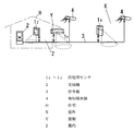
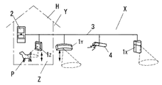
本実施形態では、図1に示すように屋内Z、住宅の外壁等の屋側Y、庭等の屋外Xに夫々パッシブ型の人体検知器からなる防犯用センサ1Z、1Y、1Xを図示するように設置し、また屋側Y及び屋外Xに設けた防犯用センサ1Z、1Y、1Xの近傍には受信機2や報知端末器4を夫々設置し、防犯用センサ1Z、1Y、1Xと受信機2や報知機器4を信号線3によって接続して夫々で情報の授受を行うことができる防犯システムを構築している。
Embodiments of the present invention will be described below.
(Embodiment 1)
In this embodiment, as shown in FIG. 1,
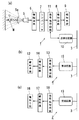
防犯用センサ1(1Z、1Y、1X)は図2(a)に示すように焦電センサ5と、この焦電センサ5が光学系手段5aを通じて受光する人体M等からの放射赤外線の変化に応じたレベルの電気信号を増幅する増幅回路6と、この増幅回路6から出力された信号レベルと予め設定している閾値とを比較して、信号レベルが閾値を越えているときに検知信号を発生させるコンパレータ7と、音を発生するブザーなどの報知機器たる報知手段9と、報知手段9を駆動する報知回路8と、コンパレータ7からの検知信号を受け取ると、設定されている報知警戒レベルで報知手段9を駆動するように報知回路8に制御信号を出力する機能と当該防犯用センサ1を識別する情報を含む検知情報を、信号線3を介して受信機2や他の防犯用センサ1、報知端末器4へ送受信回路10により送信させる機能、他の防犯用センサ1からの検知情報を送受信回路10によって受信すると予め定めたルールに基づいて報知警戒レベルを変更させる機能を有する信号処理回路11と、前記送受信回路10とで構成されている。
As shown in FIG. 2A, the security sensor 1 (1 Z , 1 Y , 1 X ) is a pyroelectric sensor 5 and infrared radiation from the human body M received by the pyroelectric sensor 5 through the optical system means 5 a. When the signal level exceeds the threshold value by comparing the
一方、報知端末器4は図2(b)に示すようにから信号線3を介して送られくる防犯用センサ1からの検知情報を受信する受信回路15と、光源などからなる報知手段12と、この報知手段12を駆動する報知回路14と、受信回路15で受信された検知情報に基づいて報知手段12を設定されている報知警戒レベルで報知回路14により動作させる制御機能及び報知警戒レベルを防犯用センサ1の検知情報に基づいて再設定する機能を有する信号処理回路13とで構成される。
On the other hand, the
受信機2は図2(c)に示すように信号線3を通じて各防犯用センサ1からの検知情報を受信する受信回路19と、ブザーのような報知手段16と、報知手段16を駆動する報知回路17と、受信回路19で受信した検知情報に基づいて報知手段16を設定されている報知警戒レベルで報知回路17により動作させる制御機能及び防犯用センサ1からの検知情報に基づいて報知警戒レベルを変更する機能を有する信号処理回路18とで構成される。
As shown in FIG. 2 (c), the
ここで防犯用センサ1の報知手段9及び受信機2の報知手段16は警報音、報知音をブザーで発生させるものであり、音量、発鳴周期を報知警戒レベルに合わせて変更できるようになっている。勿論人の声などを生成する音声発生手段にて構成しても良い。
Here, the notification means 9 of the
報知端末器4の報知手段12は光源からなり、報知警戒レベルに合わせて照度、色、点滅周期を変更できるようになっている。
The notification means 12 of the
そして何れの報知手段9,12,16においても、侵入者に対してあせりの気持ち等を発生させる度合いが報知警戒レベルが高いほど高くなるような報知形態が採用されている。勿論音発生手段と発光手段の両方を備えていても良い。 In any of the notification means 9, 12, and 16, a notification form is adopted in which the degree of occurrence of a brutal feeling or the like for an intruder increases as the notification warning level increases. Of course, both sound generating means and light emitting means may be provided.
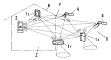
図1の場合には有線式のシステムであるが、図3に示すようにワイヤレス無線で情報の送受信を行うシステムであっても良く、この場合例えば図4(a)に示すように防犯用センサ1の送受信回路10として小電力無線を利用したワイヤレス送受信回路10’に代え、また図4(b)に示すように報知端末器4の受信回路19も小電力無線を利用したワイヤレス送受信回路15’に代え、更に図4(c)に示すように受信機2の受信回路19をワイヤレス送受信回路19’に代えれば良い。
In the case of FIG. 1, the system is a wired system, but may be a system that transmits and receives information wirelessly as shown in FIG. 3. In this case, for example, a security sensor as shown in FIG. Instead of the wireless transmission /
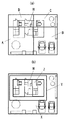
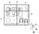
而して住宅Hを含む敷地を図5(a)に示すように隣接領域として4つの地区(A)乃至(D)を設け、図5(b)に示す住宅Hの屋外(X)、屋側(Y)、屋内(Z)の3つの検知領域の防犯用センサ1X、1Y、1Z及び報知端末器4を地区(A)〜(D)に対応させて設置した例(図6)に基づいて本実施形態の動作を説明する。
Thus, the site including the house H is provided with four districts (A) to (D) as adjacent areas as shown in FIG. 5A, and the outdoor (X) and house of the house H shown in FIG. Example in which
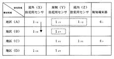
今地区(A)の屋外(X)設置の防犯用センサ11Xで侵入者が検知されると、防犯用センサ11Xでは信号処理回路11の制御の下で報知手段9から最も低い報知警戒レベルに対応した報知音(以下報知音(1)という)を発生させるとともに、検知情報を送受信回路10により報知端末器41,43及び地区(A)の屋側(Y)の防犯用センサ11Yへ送信する。
When an intruder is detected by the
この検知情報を受信回路15により受信した報知端末器41、43では信号処理回路13の制御の下で報知警戒レベルの一番低い周期(以下周期(1)という)で光源を点滅させるように報知手段12を動作させる。
In the
また地区(A)の屋側(Y)の防犯用センサ11Yでは信号処理回路11の制御の下で、侵入者検知時に報知手段9を動作させる報知警戒レベルをデフォルトの報知音(1)のレベルより二段階高い警報音(以下警報音(1)という)に設定変更する。尚地区(A)の屋内(Z)設置の防犯用センサ11Z及び受信機2の報知警戒レベルはデフォルトレベル(例えば警報音(1))のままで変更はない。
In addition, the security sensor 11Y on the shop side (Y) of the district (A) sets the alarm warning level for operating the alarm means 9 when an intruder is detected under the control of the
さて、次に侵入者が図6中矢印で示すように地区(A)から地区(B)へ移動し、当該地区(B)の屋外(X)の防犯用センサ12Xが侵入者を検知すると、上述と同様に防犯用センサ12Xでは報知手段9を信号処理回路8の制御の下で動作させ、最も低い報知警戒レベルに対応した報知音(以下報知音(1)という)を発生させる。また送受信回路10を通じて検知情報を報知端末器41,43及び地区(B)の屋側(Y)の防犯用センサ12Yへ送信する。
Next, when the intruder moves from the district (A) to the district (B) as indicated by an arrow in FIG. 6, the outdoor (X) security sensor 12X in the district (B) detects the intruder. Similarly to the above, in the security sensor 12X , the notification means 9 is operated under the control of the
この検知情報を受け取った報知端末器41、43では信号処理回路13の制御の下で報知手段12を動作させ、引き続いてデフォルトレベルである報知警戒レベルの一番低い周期(以下周期(1)という)で光源を点滅させる。
In the
また防犯用センサ12Yでは信号処理回路11の制御の下で、侵入者検知時に報知手段9を動作させる報知警戒レベルをデフォルトの報知音(1)のレベルより二段階高い警報音(以下警報音(1)という)に設定変更する。尚受信機2の報知警戒レベルは上述と同様にデフォルトレベル(例えば警報音(1))のままで変更はない。
In the security sensor 12Y , under the control of the
このように本実施形態では、侵入者が徘徊によって報知警戒レベルが変更され、屋外(X)から屋側(Y)、更に屋内(X)で侵入者が検知されると報知警戒レベルが高い報知が為され、侵入者に対して心理的な威嚇感を高めて犯罪実行を思い止めさせて最終的には敷地外へ逃走するように導き、犯罪被害を受けないようにすることができるのである。 As described above, in this embodiment, when the intruder is changed from the outdoor (X) to the shop side (Y) and further to the indoor (X), the notification warning level is high when the intruder is detected by the trap. It is possible to increase the psychological threat to intruders, stop criminal execution and eventually lead to escape from the premises, so that they can not be damaged by crime. .
尚侵入者の徘徊程度(防犯用センサ1の検知実績)により、デフォルトレベルより、一気に報知警戒レベルを上げる方法や、各防犯用センサ1で変更された報知警戒レベル中、最も高い報知警戒レベルに合わせる方法等を用いても、侵入者に対して心理的な威嚇感を高めて最終的には敷地外へ逃走するように導き、犯罪被害を受けないようにする効果は得られる。
Depending on the level of the intruder's trap (detection results of the security sensor 1), the alarm warning level can be raised from the default level at once, or the highest warning warning level among the warning warning levels changed by each
尚各機器の報知警戒レベルのデフォルトレベルと、再設定順を上述の例以外に表1に示すように設定しても良い。この場合デフォルトレベルでの報知警戒レベルが異なるとともに報知形態を異ならせている。 In addition, you may set as shown in Table 1 the default level of the alert warning level of each apparatus, and resetting order other than the above-mentioned example. In this case, the warning level at the default level is different and the notification mode is different.

(実施形態2)
本実施形態は、デフォルトレベルとして、屋外(X)、屋側(Y)、屋内(Z)の順で報知警戒レベルを高く設定しておき、異なる検出領域に設置している防犯用センサ1X、1Y、1Zが一台以上順次動作したときに、予め決められた隣接する或いは地区毎にグルーピングされた少なくとも一つの他の防犯用センサ1の報知警戒レベルを再設定するようにしたものである。
(Embodiment 2)
In this embodiment, as a default level, the alarm warning level is set higher in the order of outdoor (X), shop side (Y), indoor (Z), and the
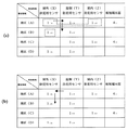
次に本実施形態の動作を図7(a)、(b)により説明する。 Next, the operation of this embodiment will be described with reference to FIGS.
まず図7(a)において、地区(A)の屋外(X)の防犯用センサ11Xが侵入者を検知すると、当該防犯用センサ11Xは信号処理回路11の制御の下で報知手段9からデフォルトレベルの報知音(1)を報知させ、また検知情報を送受信回路10により報知端末器41,43 へ送信する。これにより報知端末器41,43 では信号処理回路13の制御の下で報知手段12の光源を周期(1)で点滅させる。
First, in FIG. 7A, when the outdoor (X) security sensor 11 </ b> X in the area (A) detects an intruder, the security sensor 11 </ b > X is notified from the notification means 9 under the control of the
次に侵入者が屋側(Y)へ移動し、同じ地区(A)の屋側(Y)の防犯用センサ11Yが侵入者を検知すると、当該防犯用センサ11Yは信号処理回路11の制御の下で報知手段9からデフォルトレベルの報知音(1)を報知させる。また検知情報を送受信回路10により報知端末器41,43 へ送信する。この検知情報を受け取った報知端末器41,43 では信号処理回路13の制御の下で報知手段12を動作させ、周期(1)で光源を点滅させる。
Next, when the intruder moves to the shop side (Y) and the security sensor 11Y on the shop side (Y) in the same area (A) detects the intruder, the security sensor 11Y is connected to the
そして検知情報を送受信回路10により同じ地区(A)の屋外(X)の防犯用センサ11X及び屋内(Z)の防犯用センサ11Zへ送信し、夫々の防犯用センサ11X、11Zでの報知警戒レベルを変更させる。つまり防犯用センサ11Xでは信号処理回路11の制御の下で、利得レベルを報知音(1)のレベルより一段高い報知音(以下報知音(2)という)を報知させるレベルに変更する。また防犯用センサ11Zでは信号処理回路11の制御の下で、報知警戒レベルを報知音(1)のレベルより二段高い警報音(1)のレベルに変更する。
Then, the transmission /
その後侵入者が地区(B)へ移動し、屋側(Y)の防犯用センサ12Yが侵入者を検知すると、当該防犯用センサ12Yでは信号処理回路11の制御の下で、報知手段9を動作させ報知音(1)を報知させる。また検知情報を送受信回路10により報知端末器41,43 へ送信する。この検知情報を受け取った報知端末器41,43 では信号処理回路13の制御の下で報知警戒レベルが一段高い周期(以下周期(2)という)により光源を点滅させるように報知手段12を動作させる。
Thereafter, when the intruder moves to the district (B) and the shop side (Y) security sensor 12Y detects the intruder, the security sensor 12Y controls the notification means 9 under the control of the
また検知情報を送受信回路10により同じ地区(B)の屋外(X)の防犯用センサ12Xへ送信する。この検知情報を受け取った防犯用センサ12Xでは信号処理回路10の制御の下で報知警戒レベルを報知音(1)のレベルから報知音(2)のレベルに変更する。
Further, the detection information is transmitted to the outdoor (X) security sensor 12X in the same area (B) by the transmission /
以上の動作は報知警戒レベルが高くなる方向で順次防犯用センサ11X…が侵入者を検知した場合の報知警戒レベルの変更する動作であったが、逆に警報レベルが低くなる方向で順次防犯用センサ11X…が侵入者を検知する場合について図7(b)により説明する。
The above operation is an operation for changing the alarm warning level when the
まず図7(b)において、地区(A)の屋側(Y)の防犯用センサ11Yが侵入者を検知すると、当該防犯用センサ11Yは信号処理回路11の制御の下で報知手段9からデフォルトレベルの報知音(1)を報知させ、また検知情報を送受信回路10により報知端末器41,43 へ送信する。これにより報知端末器41,43 では信号処理回路13の制御の下で報知手段12の光源を周期(1)で点滅させる。
First, in FIG. 7 (b), the the
次に侵入者が屋外(X)へ移動し、同じ地区(A)の屋外(X)の防犯用センサ11Xが侵入者を検知すると、当該防犯用センサ11Xは信号処理回路11の制御の下で報知手段9からデフォルトレベルの報知音(1)を報知させる。また検知情報を送受信回路10により報知端末器41,43 へ送信する。この検知情報を受け取った報知端末器41,43 では信号処理回路13の制御の下で報知手段12を動作させ、周期(1)で光源を点滅させる。
Next, when the intruder moves outdoors (X) and the outdoor (X) security sensor 11X in the same area (A) detects the intruder, the security sensor 11X controls the
その後侵入者が地区(B)へ移動し、屋外(X)の防犯用センサ12Xが侵入者を検知すると、当該防犯用センサ12Xでは信号処理回路11の制御の下で、報知手段9を動作させ報知音(1)を報知させる。また検知情報を送受信回路10のより報知端末器41,43 へ送信する。この検知情報を受け取った報知端末器41,43 では信号処理回路13の制御の下で報知警戒レベルを前のまま維持して周期(1)で光源を点滅させるように報知手段12を動作させる。
Thereafter, when the intruder moves to the district (B) and the outdoor (X) security sensor 12X detects the intruder, the security sensor 12X controls the notification means 9 under the control of the
以上のように本実施形態では、報知警戒レベルが高くなる方向で順次防犯用センサ1X、1Y、1Zが侵入者を検知するような場合には報知警戒レベルを変更する処理を行って、侵入者への威嚇効果を高めるが、報知警戒レベルが低くなる方向で順次防犯用センサ1が侵入者を検知するような場合には報知警戒レベルを変更しないのである。
As described above, in the present embodiment, when the
尚図7(a)の動作例では検知動作した防犯用センサが属する同じ地区の他の防犯用センサの報知警戒レベルの変更を重み付けの上位及び下位を含めて行っているが、他地区に跨るようにレベル変更を行うようにしても良い。また重み付けの高い防犯用センサのみレベル変更を行うようにしても良い。更にまた重み付けの高い全ての防犯用センサでのレベル変更を行うようにしても良い。
(実施形態3)
上記実施形態1,2では報知警戒レベルの変更は地区(A)や検知領域等に設置された防犯用センサの動作順によって行われているが、本実施形態では何れかの防犯用センサが検知動作したときに、屋内以外の全防犯用センサの報知警戒レベルを変更するようにしたものである。
In the operation example of FIG. 7 (a), the alarm and warning level of other security sensors in the same district to which the detected security sensor belongs is changed, including the upper and lower weights, but straddles other districts. In this way, the level may be changed. Further, the level may be changed only for the security sensor having a high weight. Furthermore, the level may be changed in all security sensors with high weights.
(Embodiment 3)
In the first and second embodiments, the change of the alert warning level is performed according to the operation order of the security sensors installed in the district (A), the detection area, etc., but in this embodiment, any security sensor detects the security level. When operated, the alarm warning level of all security sensors other than indoors is changed.
この本実施形態の動作を図8により説明する。 The operation of this embodiment will be described with reference to FIG.
まず図8において、地区(A)の屋外(X)の防犯用センサ11Xが侵入者を検知すると、当該防犯用センサ11Xは信号処理回路11の制御の下で報知手段9からデフォルトレベルの報知音(1)を報知させ、また検知情報を送受信回路10により報知端末器41,43 へ送信する。これにより報知端末器41,43 では信号処理回路13の制御の下で報知手段12の光源を周期(1)で点滅させる。
First, in FIG. 8, when the outdoor (X)
次いで屋内(Z)以外の残りの防犯用センサ全てに送受信回路10を通じて検知情報を送信する。この検知情報を受け取った地区(C)、(D)の屋外(X)の防犯用センサ13X、14X では報知警戒レベルを報知音(1)のレベルから報知音(2)のレベルに信号処理回路11の制御の下で変更する。
Next, the detection information is transmitted to all remaining security sensors other than indoor (Z) through the transmission /
また検知情報を受け取った地区(A)、(B)の屋内(Z)の防犯用センサ11Z、12Zは報知警戒レベルをデフォルトレベルの警報音(1)のままとする。
The
次に侵入者が地区(B)へ移動し、地区(B)の屋外(X)の防犯用センサ12Xが侵入者を検知すると、当該防犯用センサ12Xは信号処理回路11の制御の下で報知手段9から上記のレベル変更によって報知音(2)を報知させる。また検知情報を送受信回路10により報知端末器41,43 へ送信する。この検知情報を受け取った報知端末器41,43 の内、報知端末器42では信号処理回路13の制御の下で、点滅周期を報知警戒レベルが高い周期(2)に変更して報知手段12の光源を点滅させる。
Next, when the intruder moves to the district (B) and the outdoor (X) security sensor 12X in the district (B) detects the intruder, the security sensor 12X is under the control of the
そして検知情報を送受信回路10により他の地区(B)及び(D)の屋外(X)の防犯用センサ11X、14X及び屋側(Y)の防犯用センサ11Y、12Y,13Y、14Yへ送信する。 これにより検知情報を受け取った防犯用センサ11X、14Xでは信号処理回路11の制御の下で夫々の報知警戒レベルを警報音(1)のレベルに変更する。また防犯用センサ11Y、12Y,13Y、14Yでは信号処理回路11の制御の下で報知警戒レベルを警報音(2)のレベルへ変更する。
Then, the detection information is transmitted and received by the transmission /
このように待機中において何れかの防犯用センサ11X…が検知動作を行った場合、屋内(Z)以外の残りの防犯用センサ1の報知警戒レベルを全て変更することで、侵入者の徘徊に対して威嚇効果を高める方向に報知警戒レベルを上げ、防犯態勢を確実なものとする。
In this way, when any one of the
尚異なる検知領域に侵入者の移動したことが検知されたときに、初めて全ての機器の報知警報レベルの再設定を行うようしても良い。
(実施形態4)
上記各実施形態では防犯用センサ1が検知すると、当該防犯用センサ1の報知手段10や対応する報知端末器4の報知手段12や受信機2の報知手段16による報知が行われるようになっているが、通常家人が帰宅したときに敷地内で移動する地区と当該地区の防犯用センサ1の検知順位が一定であるが、これを逸脱するような検知があったときに侵入者ありとして報知するようにしても良い。
In addition, when it is detected that an intruder has moved to a different detection area, the alarm level of all devices may be reset for the first time.
(Embodiment 4)
In the above embodiments, when the
つまり、図9に示すように通常であれば地区(A)の屋外(X)の防犯用センサ11X→屋側(Y)の防犯用センサ11Y→屋内(Z)の防犯用センサ11Zの順番で検知が為されるところを、例えば屋側(Y)の防犯用センサ11Zの動作後、地区(B)の屋側(Y)の防犯用センサ12Y→地区(C)の屋側(Y)の防犯用センサ12Yと言うように通常とは異なる順番で検知動作あった場合に報知を行うのである。
That is, as shown in FIG. 9, in the normal case, the outdoor (X)
この場合、例えば受信機2で各防犯用センサ1の検知情報の収集と分析を行い、通常の検知順と異なる検知順で検知情報を受け取ったときに、対応する防犯用センサ1や報知端末器4へ制御情報を送り、夫々に設定してある報知警戒レベルで報知手段10から報知させるようするのである。
(実施形態5)
上記各実施形態において家人が帰宅した場合に警戒解除をワイヤレス発信器などから受信機2へ指令できるようにして、家人の帰宅時に警報が出ないようにするようにしても良いが、侵入者が警戒解除を類似する発信器を用いて行うのを防ぐために、例えば個人認証用のIDコードを予め受信機2に登録しておき、図10に示すように家人MA等許可された者がワイヤレス発信器RCを発信動作させながら所定の経路で敷地内をあるくと、発信されたIDコードが受信機2で認証されると、通過しようとする検知領域或いは地区の防犯用センサの警戒状態が解除され、家人MAが通過した後には再度警戒状態をセットする制御が受信機2の制御情報に基づいて為される。
(実施形態6)
ところで、図11のように住宅H内で猫や犬のようなペットPを飼う場合が多いが、警戒中において、屋内に設置している防犯用センサ1がこれらペットを検知する恐れがある。そこで本実施形態では、屋内の防犯用センサ1が検知動作した場合、当該防犯用センサ1の信号処理回路11は屋外や屋側の防犯用センサ1が検知情報を既に送信したかどうかを判定して、送信がなければ、報知動作を行わないようにする誤動作防止機能を持たせた点に特徴がある。
In this case, for example, when the detection information of each
(Embodiment 5)
In each of the above embodiments, when the housekeeper comes home, it may be possible to instruct the
(Embodiment 6)
By the way, although there are many cases where pets P such as cats and dogs are kept in the house H as shown in FIG. 11, there is a risk that the
尚本実施形態の誤動作防止機能は記何れの実施形態にも適用できるものであるので、構成及びその他の処理動作については説明は省略する。 The malfunction prevention function of the present embodiment can be applied to any of the embodiments described above, and thus the description of the configuration and other processing operations will be omitted.
また受信機2で検知情報の一元管理を行って、上記のような判定を受信機2側で行い、報知の制御を管理するようにしても良い。
Alternatively, the detection information may be centrally managed by the
1X〜1Z 防犯用センサ
2 受信機
3 信号線
4 報知端末器
H 住宅
X 屋外
Y 屋側
Z 屋内
1 X to 1 Z
Claims (10)
A warning state setting means for canceling a warning state of one or a plurality of security sensors installed at the passing place when a person having a specific transmitter passes and resetting a warning state of the security sensor after the passage; A crime prevention system according to any one of claims 1 to 9, further comprising:
Priority Applications (1)
| Application Number | Priority Date | Filing Date | Title |
|---|---|---|---|
| JP2004191251A JP4867139B2 (en) | 2004-06-29 | 2004-06-29 | Crime prevention system |
Applications Claiming Priority (1)
| Application Number | Priority Date | Filing Date | Title |
|---|---|---|---|
| JP2004191251A JP4867139B2 (en) | 2004-06-29 | 2004-06-29 | Crime prevention system |
Publications (2)
| Publication Number | Publication Date |
|---|---|
| JP2006012018A true JP2006012018A (en) | 2006-01-12 |
| JP4867139B2 JP4867139B2 (en) | 2012-02-01 |
Family
ID=35779190
Family Applications (1)
| Application Number | Title | Priority Date | Filing Date |
|---|---|---|---|
| JP2004191251A Expired - Fee Related JP4867139B2 (en) | 2004-06-29 | 2004-06-29 | Crime prevention system |
Country Status (1)
| Country | Link |
|---|---|
| JP (1) | JP4867139B2 (en) |
Cited By (6)
| Publication number | Priority date | Publication date | Assignee | Title |
|---|---|---|---|---|
| JP2010097238A (en) * | 2008-10-14 | 2010-04-30 | Toyota Motor Corp | Security systems and buildings |
| JP2010170242A (en) * | 2009-01-21 | 2010-08-05 | Toyota Motor Corp | Security system for collective housing area |
| JP2010286950A (en) * | 2009-06-10 | 2010-12-24 | Toyota Home Kk | Security system for housing complex |
| JP2011100224A (en) * | 2009-11-04 | 2011-05-19 | Toyota Home Kk | Local security system |
| JP2014178762A (en) * | 2013-03-13 | 2014-09-25 | Osaka Gas Co Ltd | Guidance method and guidance system for guiding intruder |
| JP2017016415A (en) * | 2015-07-01 | 2017-01-19 | 株式会社Mfl | Crime prevention system and illumination device |
Citations (3)
| Publication number | Priority date | Publication date | Assignee | Title |
|---|---|---|---|---|
| JP2002109662A (en) * | 2000-10-03 | 2002-04-12 | Sekisui House Ltd | Houses and houses with security system |
| JP2003242566A (en) * | 2002-02-18 | 2003-08-29 | Optex Co Ltd | Invasion detection apparatus |
| JP2004334426A (en) * | 2003-05-06 | 2004-11-25 | Tact Presence:Kk | Intrusion crime prevention system |
-
2004
- 2004-06-29 JP JP2004191251A patent/JP4867139B2/en not_active Expired - Fee Related
Patent Citations (3)
| Publication number | Priority date | Publication date | Assignee | Title |
|---|---|---|---|---|
| JP2002109662A (en) * | 2000-10-03 | 2002-04-12 | Sekisui House Ltd | Houses and houses with security system |
| JP2003242566A (en) * | 2002-02-18 | 2003-08-29 | Optex Co Ltd | Invasion detection apparatus |
| JP2004334426A (en) * | 2003-05-06 | 2004-11-25 | Tact Presence:Kk | Intrusion crime prevention system |
Cited By (6)
| Publication number | Priority date | Publication date | Assignee | Title |
|---|---|---|---|---|
| JP2010097238A (en) * | 2008-10-14 | 2010-04-30 | Toyota Motor Corp | Security systems and buildings |
| JP2010170242A (en) * | 2009-01-21 | 2010-08-05 | Toyota Motor Corp | Security system for collective housing area |
| JP2010286950A (en) * | 2009-06-10 | 2010-12-24 | Toyota Home Kk | Security system for housing complex |
| JP2011100224A (en) * | 2009-11-04 | 2011-05-19 | Toyota Home Kk | Local security system |
| JP2014178762A (en) * | 2013-03-13 | 2014-09-25 | Osaka Gas Co Ltd | Guidance method and guidance system for guiding intruder |
| JP2017016415A (en) * | 2015-07-01 | 2017-01-19 | 株式会社Mfl | Crime prevention system and illumination device |
Also Published As
| Publication number | Publication date |
|---|---|
| JP4867139B2 (en) | 2012-02-01 |
Similar Documents
| Publication | Publication Date | Title |
|---|---|---|
| US20240346915A1 (en) | Owner controlled evacuation system | |
| US8599018B2 (en) | Alarm system having an indicator light that is external to an enclosed space for indicating the time elapsed since an intrusion into the enclosed space and method for installing the alarm system | |
| EP3096302B1 (en) | Systems and methods of detection with active infrared sensors | |
| US20160189527A1 (en) | Intelligent Object-Based Alarm System | |
| JP6139901B2 (en) | Alarm system | |
| US12347305B2 (en) | Waypoint-based premises guidance | |
| US20120293329A1 (en) | Wireless dog barking alarm system | |
| US20200126400A1 (en) | Emergency notification system | |
| JP2022177446A (en) | Security system, mobile terminal, and program | |
| JP4867139B2 (en) | Crime prevention system | |
| JP5356118B2 (en) | Crime prevention system | |
| JP2005056261A (en) | Home security system | |
| JP2007164474A (en) | Intrusion warning system | |
| JP2014026427A (en) | Monitoring system | |
| KR102219405B1 (en) | System for providing disaster information and exit guide | |
| JP4653480B2 (en) | Security equipment | |
| JP2014026426A (en) | Monitoring system | |
| JPH119559A (en) | Living abnormality detection system | |
| JP5501071B2 (en) | Security device and security method | |
| JP5363230B2 (en) | Security system | |
| JP2015001816A (en) | Report system and detector | |
| JP3003069U (en) | Security device | |
| JP5400012B2 (en) | Security equipment | |
| KR102728312B1 (en) | Smart Auditory Cpted Device For Crime Prevention | |
| Fagbohun et al. | Design of a Central Wireless Security System Using Atmega328, ZigBee and Arduino |
Legal Events
| Date | Code | Title | Description |
|---|---|---|---|
| A621 | Written request for application examination |
Free format text: JAPANESE INTERMEDIATE CODE: A621 Effective date: 20061120 |
|
| A977 | Report on retrieval |
Free format text: JAPANESE INTERMEDIATE CODE: A971007 Effective date: 20090618 |
|
| A131 | Notification of reasons for refusal |
Free format text: JAPANESE INTERMEDIATE CODE: A131 Effective date: 20091006 |
|
| A521 | Written amendment |
Free format text: JAPANESE INTERMEDIATE CODE: A523 Effective date: 20091207 |
|
| RD04 | Notification of resignation of power of attorney |
Free format text: JAPANESE INTERMEDIATE CODE: A7424 Effective date: 20100630 |
|
| A131 | Notification of reasons for refusal |
Free format text: JAPANESE INTERMEDIATE CODE: A131 Effective date: 20100706 |
|
| A521 | Written amendment |
Free format text: JAPANESE INTERMEDIATE CODE: A523 Effective date: 20100906 |
|
| A02 | Decision of refusal |
Free format text: JAPANESE INTERMEDIATE CODE: A02 Effective date: 20110628 |
|
| A521 | Written amendment |
Free format text: JAPANESE INTERMEDIATE CODE: A523 Effective date: 20110926 |
|
| A911 | Transfer of reconsideration by examiner before appeal (zenchi) |
Free format text: JAPANESE INTERMEDIATE CODE: A911 Effective date: 20111003 |
|
| TRDD | Decision of grant or rejection written | ||
| A01 | Written decision to grant a patent or to grant a registration (utility model) |
Free format text: JAPANESE INTERMEDIATE CODE: A01 Effective date: 20111018 |
|
| A01 | Written decision to grant a patent or to grant a registration (utility model) |
Free format text: JAPANESE INTERMEDIATE CODE: A01 |
|
| A61 | First payment of annual fees (during grant procedure) |
Free format text: JAPANESE INTERMEDIATE CODE: A61 Effective date: 20111031 |
|
| FPAY | Renewal fee payment (prs date is renewal date of database) |
Free format text: PAYMENT UNTIL: 20141125 Year of fee payment: 3 |
|
| LAPS | Cancellation because of no payment of annual fees |