JP2006017902A - Image display device - Google Patents
Image display device Download PDFInfo
- Publication number
- JP2006017902A JP2006017902A JP2004194142A JP2004194142A JP2006017902A JP 2006017902 A JP2006017902 A JP 2006017902A JP 2004194142 A JP2004194142 A JP 2004194142A JP 2004194142 A JP2004194142 A JP 2004194142A JP 2006017902 A JP2006017902 A JP 2006017902A
- Authority
- JP
- Japan
- Prior art keywords
- light
- optical system
- light source
- image display
- housing
- Prior art date
- Legal status (The legal status is an assumption and is not a legal conclusion. Google has not performed a legal analysis and makes no representation as to the accuracy of the status listed.)
- Pending
Links
- 230000003287 optical effect Effects 0.000 claims abstract description 87
- 238000001816 cooling Methods 0.000 claims abstract description 47
- 238000005286 illumination Methods 0.000 claims description 44
- 230000005540 biological transmission Effects 0.000 claims description 5
- 238000007664 blowing Methods 0.000 claims description 4
- 239000000428 dust Substances 0.000 abstract description 27
- 238000004519 manufacturing process Methods 0.000 abstract description 8
- QSHDDOUJBYECFT-UHFFFAOYSA-N mercury Chemical compound [Hg] QSHDDOUJBYECFT-UHFFFAOYSA-N 0.000 description 26
- 229910052753 mercury Inorganic materials 0.000 description 26
- 239000011521 glass Substances 0.000 description 11
- WABPQHHGFIMREM-UHFFFAOYSA-N lead(0) Chemical compound [Pb] WABPQHHGFIMREM-UHFFFAOYSA-N 0.000 description 7
- 238000002834 transmittance Methods 0.000 description 6
- 239000004973 liquid crystal related substance Substances 0.000 description 4
- VYPSYNLAJGMNEJ-UHFFFAOYSA-N Silicium dioxide Chemical compound O=[Si]=O VYPSYNLAJGMNEJ-UHFFFAOYSA-N 0.000 description 3
- 238000006243 chemical reaction Methods 0.000 description 3
- 239000011888 foil Substances 0.000 description 3
- 239000000463 material Substances 0.000 description 3
- XKRFYHLGVUSROY-UHFFFAOYSA-N Argon Chemical compound [Ar] XKRFYHLGVUSROY-UHFFFAOYSA-N 0.000 description 2
- 239000007789 gas Substances 0.000 description 2
- 238000005192 partition Methods 0.000 description 2
- 230000035699 permeability Effects 0.000 description 2
- 230000010287 polarization Effects 0.000 description 2
- 229910001080 W alloy Inorganic materials 0.000 description 1
- 229910052786 argon Inorganic materials 0.000 description 1
- 239000000470 constituent Substances 0.000 description 1
- 238000011109 contamination Methods 0.000 description 1
- 238000002425 crystallisation Methods 0.000 description 1
- 230000008025 crystallization Effects 0.000 description 1
- 230000006866 deterioration Effects 0.000 description 1
- 238000010586 diagram Methods 0.000 description 1
- 238000007599 discharging Methods 0.000 description 1
- 238000000295 emission spectrum Methods 0.000 description 1
- 238000000605 extraction Methods 0.000 description 1
- 230000004907 flux Effects 0.000 description 1
- 238000007496 glass forming Methods 0.000 description 1
- 229910052736 halogen Inorganic materials 0.000 description 1
- 150000002367 halogens Chemical class 0.000 description 1
- 230000020169 heat generation Effects 0.000 description 1
- 230000031700 light absorption Effects 0.000 description 1
- 230000002093 peripheral effect Effects 0.000 description 1
- 229920006395 saturated elastomer Polymers 0.000 description 1
Images




Classifications
-
- G—PHYSICS
- G03—PHOTOGRAPHY; CINEMATOGRAPHY; ANALOGOUS TECHNIQUES USING WAVES OTHER THAN OPTICAL WAVES; ELECTROGRAPHY; HOLOGRAPHY
- G03B—APPARATUS OR ARRANGEMENTS FOR TAKING PHOTOGRAPHS OR FOR PROJECTING OR VIEWING THEM; APPARATUS OR ARRANGEMENTS EMPLOYING ANALOGOUS TECHNIQUES USING WAVES OTHER THAN OPTICAL WAVES; ACCESSORIES THEREFOR
- G03B21/00—Projectors or projection-type viewers; Accessories therefor
- G03B21/10—Projectors with built-in or built-on screen
-
- G—PHYSICS
- G03—PHOTOGRAPHY; CINEMATOGRAPHY; ANALOGOUS TECHNIQUES USING WAVES OTHER THAN OPTICAL WAVES; ELECTROGRAPHY; HOLOGRAPHY
- G03B—APPARATUS OR ARRANGEMENTS FOR TAKING PHOTOGRAPHS OR FOR PROJECTING OR VIEWING THEM; APPARATUS OR ARRANGEMENTS EMPLOYING ANALOGOUS TECHNIQUES USING WAVES OTHER THAN OPTICAL WAVES; ACCESSORIES THEREFOR
- G03B21/00—Projectors or projection-type viewers; Accessories therefor
- G03B21/14—Details
- G03B21/16—Cooling; Preventing overheating
Landscapes
- Physics & Mathematics (AREA)
- General Physics & Mathematics (AREA)
- Projection Apparatus (AREA)
Abstract
Description
本発明は、光源からの照明光を、液晶パネル等の空間光変調素子を通して、スクリーンに拡大投射して画像表示を行う画像表示装置に関する。 The present invention relates to an image display apparatus that displays an image by enlarging and projecting illumination light from a light source on a screen through a spatial light modulation element such as a liquid crystal panel.
いわゆる液晶プロジェクタ装置等の画像表示装置においては、空間光変調素子となる液晶パネルを照明するための光源として、小型で高輝度の超高圧水銀ランプ等の発光管が使用されている。 In an image display device such as a so-called liquid crystal projector device, a light emitting tube such as a small and high-intensity ultra-high pressure mercury lamp is used as a light source for illuminating a liquid crystal panel serving as a spatial light modulator.
超高圧水銀ランプは、点光源に近い発光特性を有するために光利用効率が高く、また、発光管内の圧力を150気圧乃至200気圧に保つことにより、発光スペクトラムを連続発光とすることができる。また、超高圧水銀ランプは、印加エネルギーに対して可視光(波長約400nm乃至700nm)ヘの変換効率が高いので、液晶プロジェクタ装置等の画像表示装置における光源として好適である。現在、投射型の画像表示装置においては、70W乃至280Wクラスの超高圧水銀灯が使用されている。 The ultra-high pressure mercury lamp has a light emission characteristic close to that of a point light source, and therefore has high light utilization efficiency, and the emission spectrum can be continuously emitted by maintaining the pressure in the arc tube at 150 to 200 atmospheres. In addition, since the ultrahigh pressure mercury lamp has high conversion efficiency to visible light (wavelength of about 400 nm to 700 nm) with respect to applied energy, it is suitable as a light source in an image display apparatus such as a liquid crystal projector apparatus. At present, a projection type image display apparatus uses a 70 W to 280 W class ultra high pressure mercury lamp.
ところで、超高圧水銀ランプの発光性能を最大限に引き出すには、発光管の管内圧カを所定の圧力以上に高く維持しなければならず、そのためには、発光管の最冷点の温度を高く維持する必要がある。一方、長時間に亘る安定した動作を実現するためには、発光管の最高温度を所定の温度以下に抑えて、発光管を構成する石英ガラスの結晶化を防ぐ必要がある。 By the way, in order to maximize the luminous performance of the ultra-high pressure mercury lamp, the pressure inside the arc tube must be kept higher than a predetermined pressure. For this purpose, the temperature at the coldest spot of the arc tube must be maintained. Need to keep high. On the other hand, in order to realize a stable operation for a long time, it is necessary to suppress the crystallization of quartz glass constituting the arc tube by suppressing the maximum temperature of the arc tube to a predetermined temperature or less.
すなわち、超高圧水銀ランプを使用するにあたっては、発光管の温度が所定の温度範囲内となるように、適切な冷却を行う必要がある。 That is, when using an ultra high pressure mercury lamp, it is necessary to perform appropriate cooling so that the temperature of the arc tube is within a predetermined temperature range.
そのため、従来の画像表示装置においては、発熱量の大きな超高圧水銀ランプの周辺部分と、この超高圧水銀ランプからの照明光が入射される光学部品とを、それぞれ別個に冷却する構成が採用されている。 Therefore, the conventional image display device employs a configuration in which the peripheral portion of the ultra-high pressure mercury lamp having a large calorific value and the optical component to which the illumination light from the ultra-high pressure mercury lamp is incident are separately cooled. ing.
例えば、特許文献1には、図9に示すように、筐体106の上部側の密閉空間109内に空間光変調素子及び投射光学系からなる光学ブロック102を配置するとともに、発熱量の大きな電源回路105及びランプ101は、筐体の下部側の開放空間112内に配置して構成した画像表示装置が記載されている。
For example, in Patent Document 1, as shown in FIG. 9, an
上部側の密閉空間109と下部側の開放空間112とは、隔壁107によって分離されている。
The upper closed
この画像表示装置においては、光学ブロック102は、冷却ファン108が上部側の密閉空間109内の空気を循環させることによって冷却される。そして、電源回路105及びランプ101は、これら電源回路105及びランプ101により加熱された空気が筐体の外部に排出されるとともに、筐体の外部から新たな冷却風が取り込まれることにより、冷却される。
前述したような従来の画像表示装置においては、光源からの照明光が入射される光学部品の光入射面の汚れや塵壊の付着を防止するため、筐体における密閉空間内で空気を循環させることによって冷却するようにしていた。 In the conventional image display apparatus as described above, air is circulated in a sealed space in the housing in order to prevent the light incident surface of the optical component on which the illumination light from the light source is incident from being attached and dirt from being attached. It was trying to cool by.
しかしながら、筐体内を密閉構造にして外気と遮断しても、大きな容積を有する筐体内には、塵挨が入り込み易く、光学部品に汚れや塵壊の付着が発生する虞れがある。 However, even if the inside of the housing is sealed and shut off from the outside air, dust can easily enter the housing having a large volume, and there is a possibility that dirt or dust will adhere to the optical components.
このような汚れや塵挨の付着の原因としては、筐体の組み立て時に、この筐体を構成する構造材、あるいは、光学ブロックを構成する光学部品やその構成材に、塵挨が付着し、あるいは、塵挨が閉じ込められることが考えられ、また、通常の使用時においても、筐体内の空気が膨張及び収縮を繰り返すことにより、筐体を構成する構造材に隙間が生じ、この隙間から塵挨が混入することが考えられる。 As a cause of such dirt and dust adhesion, when the housing is assembled, dust adheres to the structural material constituting the housing, or to the optical parts and the constituent materials constituting the optical block, Alternatively, it is conceivable that dust is trapped, and even during normal use, the air in the housing repeatedly expands and contracts, creating a gap in the structural material that constitutes the housing. It is possible that dust is mixed.
このような組み立て時における塵挨の混入や、使用時における筐体内への塵挨の侵入を完全に無くすことは困難であり、このような塵挨の混入や侵入を完全に無くそうとすれば、製造の困難化、製造コストの高騰が招来されてしまう。 It is difficult to completely eliminate dust contamination during assembly and dust intrusion into the housing during use. Therefore, the manufacturing becomes difficult and the manufacturing cost increases.
そこで、本発明は、前述の実情に鑑みて提案されるものであって、製造の困難化や製造コストの高騰を招来することなく、光源からの照明光が入射される光学部品の光入射面の汚れや塵壊の付着が確実に防止されるようになされた画像表示装置を提供することを目的とする。 Therefore, the present invention is proposed in view of the above-described circumstances, and the light incident surface of the optical component on which the illumination light from the light source is incident without causing difficulty in manufacturing and an increase in manufacturing cost. An object of the present invention is to provide an image display device that can reliably prevent dirt and dust from adhering.
前述の課題を解決し、前記目的を達成するため、本発明に係る画像表示装置は、スクリーンの背面側から画像光を投射してこのスクリーンを透して前面側に向けて画像表示を行う画像表示装置であって、装置の前面側がスクリーンとなされた密閉構造の筐体と、光源と、筐体内に収納されスクリーンに対して画像光を投射するためのインテグレータ光学系とこのインテグレータ光学系によって照明される空間光変調素子とこの空間光変調素子の変調光をスクリーンの背面側に結像させる投射光学系とからなる光学系ブロックと、光学系ブロックを構成する光学部品を冷却するために筐体内の空気をこの筐体内において循環させる送風手段とを備え、光源からの照明光が透過する各光学部品の光透過面は、略々鉛直面となされているとともに、これら光透過面には、送風手段により、風速が秒速1.5m以上の冷却風が送られることを特徴とするものである。 In order to solve the above-described problems and achieve the above object, an image display device according to the present invention projects an image light from the back side of a screen and displays the image toward the front side through the screen. A display device having a sealed structure with a screen on the front side of the device, a light source, an integrator optical system housed in the housing for projecting image light onto the screen, and illumination by the integrator optical system An optical system block composed of a spatial light modulation element and a projection optical system that forms an image of the modulated light of the spatial light modulation element on the back side of the screen, and a housing for cooling the optical components constituting the optical system block A light transmitting surface of each optical component through which the illumination light from the light source is transmitted is substantially a vertical surface. The these light transmitting surface, the blowing means, the wind speed is characterized in that the cooling air over per second 1.5m is sent.
この画像表示装置においては、光源からの照明光が透過する各光学部品の光透過面は、略々鉛直面となされているので、塵挨等が付着しにくく、また、風速が秒速1.5m以上の冷却風が送られることにより、塵挨等の付着が確実に防止される。 In this image display device, the light transmitting surface of each optical component through which the illumination light from the light source is transmitted is substantially vertical, so that dust and the like are not easily attached, and the wind speed is 1.5 m / s. By sending the cooling air described above, adhesion of dust and the like is reliably prevented.
本発明に係る画像表示装置においては、光源からの照明光が透過する各光学部品の光透過面が略々鉛直面となされていることにより、これら光透過面に対して塵挨等が付着しにくくなっている。また、この画像表示装置においては、これら光透過面に、風速が秒速1.5m以上の冷却風を送っていることによって、塵挨等の付着を確実に防止することができる。そして、画像表示装置においては、光学部品に対する汚れや塵挨の付着が防止されることにより、これら光学部品における光透過率の劣化や、光吸収による発熱が防止される。 In the image display device according to the present invention, since the light transmission surface of each optical component that transmits illumination light from the light source is substantially vertical, dust or the like adheres to these light transmission surfaces. It has become difficult. Moreover, in this image display apparatus, dust and the like can be reliably prevented from being sent to these light transmission surfaces by sending cooling air having a wind speed of 1.5 m / s or more. In the image display device, dirt and dust are prevented from adhering to the optical components, so that deterioration of light transmittance in these optical components and heat generation due to light absorption are prevented.
すなわち、本発明は、製造の困難化や製造コストの高騰を招来することなく、光源からの照明光が入射される光学部品の光入射面の汚れや塵壊の付着が確実に防止されるようになされた画像表示装置を提供することができるものである。 That is, according to the present invention, dirt on the light incident surface of the optical component on which the illumination light from the light source is incident and dust adhesion are reliably prevented without causing difficulty in production or an increase in production cost. It is possible to provide an image display device made in the above.
以下、本発明を実施するための最良の形態について、図面を参照しながら詳細に説明する。 Hereinafter, the best mode for carrying out the present invention will be described in detail with reference to the drawings.
図1は、本発明の実施形態に係る画像表示装置の概略構成を示す斜視図である。 FIG. 1 is a perspective view showing a schematic configuration of an image display apparatus according to an embodiment of the present invention.
この画像表示装置は、図1に示すように、筐体30を備えて構成され、この筐体30の下方部分に、光学系ブロックが設置されて構成されている。
As shown in FIG. 1, the image display device is configured to include a
図2は、本発明の実施形態に係る画像表示装置における光学系ブロックの構成を示す斜視図である。 FIG. 2 is a perspective view showing a configuration of an optical system block in the image display apparatus according to the embodiment of the present invention.
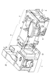
光学系ブロックは、図2に示すように、光源装置を内蔵した照明光源ユニット1と、照明光源ユニット1からの照明光の照度を均一化させるインテグレータ光学系2と、光変調部3と、結像光学系である投射光学系4とから構成されている。これら光学系ブロックをなす各部分は、筐体に収納されて構成されている。
As shown in FIG. 2, the optical system block includes an illumination light source unit 1 including a light source device, an integrator
この光学系ブロックは、照明光源ユニット1より発せられインテグレータ光学系2を経て光変調部3に至った照明光を、この光変調部3において空間光変調素子によって画像情報に基づいて空間変調し、このように空間変調された照明光を投射光学系4によって斜め上方に向けて投射する。画像表示装置においては、図1に示すように、投射光学系4より投射された照明光は、筐体30内に設置されたミラー31によって反射されて、この画像表示装置の前面部をなす半透明スクリーン32に、この半透明スクリーン32の背面側より投射される。このように半透明スクリーン32に投射された照明光は、この半透明スクリーン32上に表示画像を結像させる。
This optical system block spatially modulates illumination light emitted from the illumination light source unit 1 and passed through the integrator
この画像表示装置の筐体30においては、ミラー31及び半透明スクリーン32が設置された上部側空間33と、光学系ブロックが設置さた下部側空間34とが、隔壁によって分けられている。上部側空間33は、外部からの光の進入、内部から外部への光漏れ及び塵埃の侵入を防ぐため、略々密閉された空間となっている。
In the
そして、光学系ブロックのうち、インテグレータ光学系2、光変調部3及び投射光学系4を収納した筐体は、筐体30の上部側空間33と、複数のダクトを介してつながっている。一方、光学系ブロックのうち、照明光源ユニット1を収納した筐体は、筐体30の下部側空間34と、複数のダクトを介してつながっている。すなわち、この光学系ブロックにおいて、照明光源ユニット1を収納した筐体と、インテグレータ光学系2、光変調部3及び投射光学系4を収納した筐体とは、互いの内部の空気が流通することのないように分離されている。
And the housing | casing which accommodated the integrator
インテグレータ光学系2、光変調部3及び投射光学系4の冷却は、画像表示装置の筐体の上部側空間33において、送風手段により、空気を循環させることによって行われる。すなわち、これらインテグレータ光学系2、光変調部3及び投射光学系4の冷却は、図2中矢印Aで示すように、筐体30の上部側空間33内の空気がダクトを介して光学系ブロックの筐体内に送り込まれることによって行われる。インテグレータ光学系2、光変調部3及び投射光学系4を冷却した空気は、図2中矢印Bで示すように、光学系ブロックの筐体から排出され、ダクトを介して、筐体30の上部側空間33に戻される。この筐体30の上部側空間33内の空気は、この上部側空間33内及びインテグレータ光学系2、光変調部3及び投射光学系4を収納した筐体内において、図示しない冷却ファン等からなる冷却手段により、循環するようになっている。
Cooling of the integrator
照明光源ユニット1を除くインテグレータ光学系2、光変調部3及び投射光学系4においては、照明光源ユニット1からの照射光を、透光性光学部品が吸収することによる発熱が主である。したがって、略々密閉した筐体30の上部側空間33内を循環する冷却風によって十分な冷却を行うことができる。
In the integrator
一方、照明光源ユニット1の冷却は、図2に示すように、冷却手段となる軸流ファン12により、筐体30の下部側空間34に外部から取り入れた空気によって行われる。この軸流ファン12によって照明光源ユニット1内に送られ、この照明光源ユニット1を冷却した冷却風は、ダクト23を介して、筐体30の外方側に排出される。
On the other hand, the illumination light source unit 1 is cooled by air taken into the
この照明光源ユニット1における発熱量は、光学系ブロックの中で最も大きい。そのため、この冷却風は、筐体30外から取り入れられ、照明光源ユニット1を冷却した後は筐体30外ヘ排出され、他の光学系に熱的な影響を与えにくいようになっている。
The amount of heat generated in the illumination light source unit 1 is the largest among the optical system blocks. For this reason, this cooling air is taken from outside the
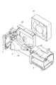
図3は、照明光源ユニット1の構成を示す分解斜視図である。 FIG. 3 is an exploded perspective view showing the configuration of the illumination light source unit 1.
照明光源ユニット1は、図3に示すように、超高圧水銀ランプユニット5を備えている。この超高圧水銀ランプユニット5は、発光管である超高圧水銀ランプと、この超高圧水銀ランプを保持する凹面リフレクタ14とを有して構成されている。この超高圧水銀ランプユニット5は、筐体状のランプハウジング6内に挿入され、押さえブラケット7により、このランプハウジング6に対して固定されている。
The illumination light source unit 1 includes an ultrahigh pressure mercury lamp unit 5 as shown in FIG. The ultra-high pressure mercury lamp unit 5 includes an ultra-high pressure mercury lamp that is an arc tube and a
この超高圧水銀ランプユニット5においては、発光管の発光点は凹面リフレクタ14内に位置しており、この発光点から発せられた照明光は、凹面リフレクタ14の内面の凹面反射面によって反射されて、前方側に出射される。このように出射される光束の光軸は、略々水平となされている。
In this ultra high pressure mercury lamp unit 5, the light emitting point of the arc tube is located in the
なお、この超高圧水銀ランプユニット5は、通常は、ランプハウジング6に収納された状態で交換部品として取り扱われており、ランプ交換等は、ランプハウジング6に収納されたままの状態で行われる。
The ultra-high pressure mercury lamp unit 5 is normally handled as a replacement part in a state of being housed in the
そして、この照明光源ユニット1においては、ランプハウジング6の側方から、軸流ファン12によって、超高圧水銀ランプユニット5の側面部に対して冷却風が吹き付けられる。
In the illumination light source unit 1, cooling air is blown from the side of the
ランプハウジング6と軸流ファン12の間には、押さえブラケット7に取り付けられた風向ガイド24が設置されている。この風向ガイド24が軸流ファン12からの冷却風を導くことにより、ランプハウジング6内には、このランプハウジング6に設けられた冷却風取り込み口より、効率良く冷却風が導入される。
Between the
なお、照明光源ユニット1の近傍に軸流ファン12を配置できない場合には、この照明光源ユニット1から離れた場所に軸流ファン12を配置しても、この軸流ファン12から照明光源ユニット1に至る導風路を形成すれば、照明光源ユニット1を効率良く冷却することができる。
If the
図4Aは、超高圧水銀ランプユニット5の構成を示す斜視図である。 FIG. 4A is a perspective view showing the configuration of the extra-high pressure mercury lamp unit 5.
超高圧水銀ランプユニット5は、図4Aに示すように、内面に赤外光領域を透過するコールドミラー反射膜が形成された回転楕円体、あるいは、回転放物面体等の凹面リフレクタ14を有し、この凹面リフレクタ14の最凹部に両端封止型の発光管が固定されて構成されている。凹型リフレクタ14の前端部は開放された光照射開口部となっており、この光照射開口部は、透明ガラス11により閉蓋されている。この超高圧水銀ランプユニット5においては、凹面リフレクタ14と透明ガラス11とは、内部を略々密閉した構造となっている。
As shown in FIG. 4A, the ultra-high pressure mercury lamp unit 5 has a
発光管の第1電極9は、凹面リフレクタ14の最凹部に設けられた孔を介して、この凹面リフレクタ14の外部に後方側に向けて引き出されている。
The
図4Bは、超高圧水銀ランプユニット5の内部構造を一部を破断して示す斜視図である。 FIG. 4B is a perspective view showing the internal structure of the ultrahigh pressure mercury lamp unit 5 with a part thereof broken.
発光管8の第2電極10には、リード線18の一端側が接続されている。このリード線18の他端側は、凹面リフレクタ14の曲斜面、あるいは、側面に設けられた引出孔19を介して、この凹面リフレクタ14の外部に引き出されている。このようにリード線18の他端側が外方側に引き出される方向としては、凹面リフレクタ14から出射される照明光の光軸に対して、斜め上方とすることが好ましい。
One end of a
そして、第1電極9及びリード線18の他端側は、導電線13,13を介して、コネクタ13aにそれぞれ接続されている。コネクタ13aは、ランプハウジング6に固定されており、照明光源ユニット1を光学系ブロックに装着したときに、図示しない発光管駆動電源に接続されるようになっている。
And the other end side of the
両端封止型の発光管8は、基本構造としては、石英ガラスで形成したバルブ内に、水銀、アルゴンガス及び微量のハロゲンガスが封入されているものである。このバルブの中心部分が発光点となる。バルブ内には、タングステン合金からなる放電電極が1mm乃至1.5mmの間隔を介して互いの先端部を対向させて配置されている。これら放電電極の基端側には、モリプデン箔が接統されており、さらに、これらモリプデン箔に、外部引き出し電極である第1電極9及び第2電極10が接続されている。これら第1電極9及び第2電極10は、バルブの両端側に向けて、それぞれバルブの外方側に引き出されている。モリプデン箔の部分は、バルブをなす石英ガラスに対して密着封止している。
Both ends sealed
図5は、照明光源ユニット1の構成を示す軸流ファン12側から見た分解斜視図である。
FIG. 5 is an exploded perspective view showing the configuration of the illumination light source unit 1 as seen from the
超高圧水銀ランプユニット5を覆うランプハウジング6の側面部には、図5に示すように、凹面リフレクタ14を冷却するための第1の冷却風15が導入される開口部6aと、リード線18の他端側を冷却するための第2の冷却風16が導入される開口部6bとが形成されている。
As shown in FIG. 5, the side surface of the
なお、ランプハウジング6の側面部においては、軸流ファン12の中心部分のモータに対向する部分は閉塞されている。軸流ファン12においては、中心部分から送られる冷却風は少ないので、この中心部分に対抗する部分を閉塞することにより、この部分の周囲の開口部6a,6bを介して、凹面リフレクタ14及びリード線18の他端側に対して、第1及び第2の冷却風15,16が集中して送られることとなる。
In addition, in the side part of the
この画像表示措置においては、凹面リフレクタ14から出射される照明光の光軸から見て斜め上方、かつ、第2の冷却風16の風上側に突出されたリード線18の他端側部分を冷却する第2の冷却風16は、このリード線18の他端側部分を集中的に冷却し、その後、凹面リフレクタ14の上側部分、すなわち、高温部を冷却するので、バランスの良い良好な冷却が行われる。
In this image display measure, the other end portion of the
図6は、照明光源ユニット1の周辺の構成を示す斜視図である。 FIG. 6 is a perspective view showing a configuration around the illumination light source unit 1.
また、ランプハウジング6と押さえプラケット7との間には、図6に示すように、凹型リフレクタ14の光照射開口部を閉蓋している透明ガラス11を冷却するための第3の冷却風17が導入される開口部が設けられている。この第3の冷却風17は、透明ガラス11のみならず、インテグレータ光学系2の光入射面となるUV/IRカットフィルタ(紫外線赤外線反射フィルタ)22をも冷却する。
Further, as shown in FIG. 6, a third cooling air 17 for cooling the
なお、この実施形態においては、軸流ファン12と照射光源ユニット1の間を密閉した通風路とはしておらず、これら軸流ファン12と照射光源ユニット1の間から周辺に漏れた冷却風によって、ランプハウジング6及び押さえブラケット7の外側部をも冷却する構成となっている。
In this embodiment, the air flow between the
ここで、照射光源ユニット1及びその周辺を冷却する各冷却風15,16,17は、外部より取り込まれた外気である。これら冷却風には、若干の塵挨が舎まれており、これら塵挨が光学部品に付着する虞れがある。
Here, each cooling
特に、超高圧水銀ランプユニット5の前面部を閉蓋する透明ガラス11と、UV/IRカットフィルタ22の表面に塵挨が付着すると、これら塵挨により照明光が吸収され、表示画像の輝度が著しく劣化することになる。
In particular, when dust adheres to the surface of the
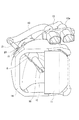
図7は、インテグレータ光学系2の構成を示す斜視図である。なお、この図7は、密閉された空間に配置された光学部品を示すため、上部のカバーを外した状態の図となっている。
FIG. 7 is a perspective view showing the configuration of the integrator
照射光源ユニット1から出射された照射光は、図7に示すように、UV/IRフィルタ22を透過して、密閉空間となされたインテグレータ光学系2に入射される。このインテグレータ光学系2に入射された照射光は、光軸に対して45°傾斜された壁面25の内面部に配置された反射ミラーにより90度曲げられ、第1フライアイレンズ及び偏光変換プリズム群26、第2フライアイレンズ27、第1フィールドレンズ28及び図示しない偏光板等を透過して、光変調部3に向かう。
As shown in FIG. 7, the irradiation light emitted from the irradiation light source unit 1 is transmitted through the UV /
このインテグレータ光学系2を構成する各光学部品、すなわち、UV/IRフィルタ22、反射ミラー、第1フライアイレンズ及び偏光変換プリズム群26、第2フライアイレンズ27、第1フィールドレンズ28及び偏光板と、照射光源ユニット1の透明ガラス11とは、光入射面及び光出射面が鉛直面となされて配置されている。
Each optical component constituting the integrator
したがって、これら各光学部品の光入射面及び光出射面には、塵挨が堆積して付着することがない。 Therefore, dust does not accumulate and adhere to the light incident surface and the light emitting surface of each optical component.
そして、この画像表示措置において、前述した各冷却手段によって各光学部品に送られる冷却風は、各光学部品の光入射面及び光出射面における風速が、秒速1.5m以上となるようになっている。 And in this image display measure, the cooling wind sent to each optical component by each cooling means described above is such that the wind speed at the light incident surface and light exit surface of each optical component is 1.5 m / s or more. Yes.
図8は、透明ガラス11とUV/IRカットフィルタ22の間に流れる冷却風17の風速と透過率の変動との関係を示すグラフである。
FIG. 8 is a graph showing the relationship between the wind speed of the cooling air 17 flowing between the
ここで、透明ガラス11とUV/IRカットフィルタ22との間に流れる第3の冷却風17の風速と、これら透明ガラス11及びUV/IRカットフィルタ22の透過率との関係を調べると、図8に示すように、第3の冷却風17の風速が小さいと、透過率が落ちており、光学部品の表面に塵挨が付着していることがわかる。そして、第3の冷却風17の風速を徐々に上げていくと、透過率も上がり、風速が秒速1.5m以上では、略々飽和した状態となっている。
Here, when the relationship between the wind speed of the third cooling air 17 flowing between the
すなわち、各光学部品の光入射面及び光出射面における風速を秒速1.5m以上とすれば、これら光学部品の表面への塵挨の付着を防止することができることがわかる。 That is, it can be seen that if the wind velocity at the light incident surface and the light exit surface of each optical component is 1.5 m or more per second, dust can be prevented from adhering to the surfaces of these optical components.
なお、図8に示したデータは、高濃度の塵挨中に、画像表示措置を動作状態で放置して得たものであり、塵挨の濃度等の条件は、「JIS D 0207」(防塵及び耐塵試験通則)に準拠したものとして行った。 The data shown in FIG. 8 is obtained by leaving the image display measure in an operating state in high-concentration dust, and the conditions such as the dust concentration are “JIS D 0207” (dust-proof And the dust resistance test general rules).
なお、冷却風を筐体外より取り込むにあたっては、この冷却風を塵挨除去フィルタを介して取り込むようにしてもよい。 In addition, when taking in cooling air from the outside of a housing | casing, you may make it take in this cooling air via a dust removal filter.
1 照明光源ユニット
2 インテグレータ光学系
3 光変調部
4 投射光学系
5 超高圧水銀ランプユニット
6 ランプハウジング
7 押さえブラケット
8 発光管
9 第1電極
10 第2電極
11 透明ガラス
12 軸流ファン
13 コネクタ
14 凹面リフレクタ
15 第1の冷却風
16 第2の冷却風
17 第3の冷却風
22 UV/IRカットフィルタ
DESCRIPTION OF SYMBOLS 1 Illumination
Claims (1)
装置の前面側が前記スクリーンとなされた密閉構造の筐体と、
光源と、
前記筐体内に収納され前記スクリーンに対して画像光を投射するためのインテグレータ光学系と、このインテグレータ光学系によって照明される空間光変調素子と、この空間光変調素子の変調光を前記スクリーンの背面側に結像させる投射光学系とからなる光学系ブロックと、
前記光学系ブロックを構成する光学部品を冷却するために、前記筐体内の空気を、この筐体内において循環させる送風手段と、
を備え、
前記光源からの照明光が透過する各光学部品の光透過面は、略々鉛直面となされているとともに、これら光透過面には、前記送風手段により、風速が秒速1.5m以上の冷却風が送られる
ことを特徴とする画像表示装置。 An image display device that projects image light from the back side of the screen and displays the image toward the front side through the screen,
A sealed housing having the screen on the front side of the device;
A light source;
An integrator optical system that is housed in the housing and projects image light onto the screen, a spatial light modulation element that is illuminated by the integrator optical system, and the modulated light of the spatial light modulation element on the back surface of the screen An optical system block comprising a projection optical system that forms an image on the side;
In order to cool the optical components constituting the optical system block, air blowing means for circulating the air in the casing in the casing;
With
The light transmission surfaces of the optical components through which the illumination light from the light source passes are substantially vertical surfaces. The light transmission surfaces are provided with cooling air having a wind speed of 1.5 m / s or more by the blowing means. An image display device characterized in that
Priority Applications (1)
| Application Number | Priority Date | Filing Date | Title |
|---|---|---|---|
| JP2004194142A JP2006017902A (en) | 2004-06-30 | 2004-06-30 | Image display device |
Applications Claiming Priority (1)
| Application Number | Priority Date | Filing Date | Title |
|---|---|---|---|
| JP2004194142A JP2006017902A (en) | 2004-06-30 | 2004-06-30 | Image display device |
Publications (1)
| Publication Number | Publication Date |
|---|---|
| JP2006017902A true JP2006017902A (en) | 2006-01-19 |
Family
ID=35792261
Family Applications (1)
| Application Number | Title | Priority Date | Filing Date |
|---|---|---|---|
| JP2004194142A Pending JP2006017902A (en) | 2004-06-30 | 2004-06-30 | Image display device |
Country Status (1)
| Country | Link |
|---|---|
| JP (1) | JP2006017902A (en) |
Citations (17)
| Publication number | Priority date | Publication date | Assignee | Title |
|---|---|---|---|---|
| JPH07255027A (en) * | 1994-03-15 | 1995-10-03 | Mitsubishi Electric Corp | Screen storage type projection display device |
| JPH09222665A (en) * | 1996-02-19 | 1997-08-26 | West Electric Co Ltd | Picture projector |
| JP2000112033A (en) * | 1998-09-30 | 2000-04-21 | Sanyo Electric Co Ltd | Video projecting device |
| JP2000147449A (en) * | 1998-11-09 | 2000-05-26 | Matsushita Electric Ind Co Ltd | LCD projection TV |
| JP2000258840A (en) * | 1999-03-04 | 2000-09-22 | Seiko Epson Corp | Projection display device |
| JP2000348748A (en) * | 1999-06-08 | 2000-12-15 | Honda Motor Co Ltd | Fuel cell power generation control method |
| JP2002006283A (en) * | 2000-06-27 | 2002-01-09 | Toshiba Corp | LCD projector device |
| JP2002006392A (en) * | 2000-06-26 | 2002-01-09 | Toshiba Corp | Projector device |
| JP2002152634A (en) * | 2000-11-15 | 2002-05-24 | Toshiba Corp | Heating protection device and projection display device |
| JP2002207168A (en) * | 2000-05-10 | 2002-07-26 | Mitsubishi Electric Corp | Image display device and alignment adjustment method |
| JP2002341443A (en) * | 2001-05-18 | 2002-11-27 | Hitachi Ltd | Projection type video display |
| JP2002350806A (en) * | 2001-05-25 | 2002-12-04 | Nec Viewtechnology Ltd | Liquid crystal projector |
| JP2002372748A (en) * | 2001-06-15 | 2002-12-26 | Minolta Co Ltd | Projector |
| JP2003057755A (en) * | 2001-08-13 | 2003-02-26 | Canon Inc | Projection display device |
| JP2003262916A (en) * | 2002-12-26 | 2003-09-19 | Seiko Epson Corp | Projection display device |
| JP2003302697A (en) * | 2002-04-10 | 2003-10-24 | Ricoh Co Ltd | Lighting device and liquid crystal projector |
| JP2003337380A (en) * | 2002-05-21 | 2003-11-28 | Sharp Corp | Projection display device |
-
2004
- 2004-06-30 JP JP2004194142A patent/JP2006017902A/en active Pending
Patent Citations (17)
| Publication number | Priority date | Publication date | Assignee | Title |
|---|---|---|---|---|
| JPH07255027A (en) * | 1994-03-15 | 1995-10-03 | Mitsubishi Electric Corp | Screen storage type projection display device |
| JPH09222665A (en) * | 1996-02-19 | 1997-08-26 | West Electric Co Ltd | Picture projector |
| JP2000112033A (en) * | 1998-09-30 | 2000-04-21 | Sanyo Electric Co Ltd | Video projecting device |
| JP2000147449A (en) * | 1998-11-09 | 2000-05-26 | Matsushita Electric Ind Co Ltd | LCD projection TV |
| JP2000258840A (en) * | 1999-03-04 | 2000-09-22 | Seiko Epson Corp | Projection display device |
| JP2000348748A (en) * | 1999-06-08 | 2000-12-15 | Honda Motor Co Ltd | Fuel cell power generation control method |
| JP2002207168A (en) * | 2000-05-10 | 2002-07-26 | Mitsubishi Electric Corp | Image display device and alignment adjustment method |
| JP2002006392A (en) * | 2000-06-26 | 2002-01-09 | Toshiba Corp | Projector device |
| JP2002006283A (en) * | 2000-06-27 | 2002-01-09 | Toshiba Corp | LCD projector device |
| JP2002152634A (en) * | 2000-11-15 | 2002-05-24 | Toshiba Corp | Heating protection device and projection display device |
| JP2002341443A (en) * | 2001-05-18 | 2002-11-27 | Hitachi Ltd | Projection type video display |
| JP2002350806A (en) * | 2001-05-25 | 2002-12-04 | Nec Viewtechnology Ltd | Liquid crystal projector |
| JP2002372748A (en) * | 2001-06-15 | 2002-12-26 | Minolta Co Ltd | Projector |
| JP2003057755A (en) * | 2001-08-13 | 2003-02-26 | Canon Inc | Projection display device |
| JP2003302697A (en) * | 2002-04-10 | 2003-10-24 | Ricoh Co Ltd | Lighting device and liquid crystal projector |
| JP2003337380A (en) * | 2002-05-21 | 2003-11-28 | Sharp Corp | Projection display device |
| JP2003262916A (en) * | 2002-12-26 | 2003-09-19 | Seiko Epson Corp | Projection display device |
Similar Documents
| Publication | Publication Date | Title |
|---|---|---|
| KR100636438B1 (en) | Light source device and projector | |
| AU761761B2 (en) | Liquid crystal projection apparatus and lamp | |
| US7188973B2 (en) | Optical image projector and light source device for optical image projector | |
| CN100533261C (en) | Projection type image display apparatus | |
| US7380965B2 (en) | Light source apparatus, optical apparatus, and image projection apparatus | |
| JP4774762B2 (en) | LIGHT SOURCE DEVICE AND PROJECTOR HAVING THE SAME | |
| US7367679B2 (en) | Light source for a display device | |
| JP4656973B2 (en) | Light source device and projection display device | |
| JP4438626B2 (en) | Light source device and image display device | |
| CN1873520B (en) | Projection display | |
| JP2005070216A (en) | LIGHTING DEVICE AND PROJECTOR HAVING THE SAME | |
| JP2001076505A (en) | Lighting equipment | |
| JP4090272B2 (en) | Light source device | |
| JP2004219752A (en) | Video projection device and cooling method for video projection device | |
| CN100533262C (en) | Light source device, optical device, and image projection device | |
| JP2006017902A (en) | Image display device | |
| JP4240095B2 (en) | Sealed lamp device and projector | |
| JP2011209382A (en) | Light source device and projector | |
| JP4640639B2 (en) | Light source device and image display device | |
| JP2008016394A (en) | Light source device, illumination device, and projector device | |
| JPH11249235A (en) | Lighting device and projector | |
| JP2004294986A (en) | Projection display device | |
| JP2002260437A (en) | Light source unit | |
| KR20050107701A (en) | Projection television | |
| JP2013015654A (en) | Light source device and projector |
Legal Events
| Date | Code | Title | Description |
|---|---|---|---|
| A621 | Written request for application examination |
Free format text: JAPANESE INTERMEDIATE CODE: A621 Effective date: 20060630 |
|
| A131 | Notification of reasons for refusal |
Free format text: JAPANESE INTERMEDIATE CODE: A131 Effective date: 20090424 |
|
| A521 | Written amendment |
Free format text: JAPANESE INTERMEDIATE CODE: A523 Effective date: 20090619 |
|
| A131 | Notification of reasons for refusal |
Free format text: JAPANESE INTERMEDIATE CODE: A131 Effective date: 20100309 |
|
| A02 | Decision of refusal |
Free format text: JAPANESE INTERMEDIATE CODE: A02 Effective date: 20100629 |