JP2006037745A - Internal combustion engine - Google Patents
Internal combustion engine Download PDFInfo
- Publication number
- JP2006037745A JP2006037745A JP2004214687A JP2004214687A JP2006037745A JP 2006037745 A JP2006037745 A JP 2006037745A JP 2004214687 A JP2004214687 A JP 2004214687A JP 2004214687 A JP2004214687 A JP 2004214687A JP 2006037745 A JP2006037745 A JP 2006037745A
- Authority
- JP
- Japan
- Prior art keywords
- internal combustion
- combustion engine
- reformed gas
- gas
- reforming
- Prior art date
- Legal status (The legal status is an assumption and is not a legal conclusion. Google has not performed a legal analysis and makes no representation as to the accuracy of the status listed.)
- Pending
Links
Images

Classifications
-
- F—MECHANICAL ENGINEERING; LIGHTING; HEATING; WEAPONS; BLASTING
- F02—COMBUSTION ENGINES; HOT-GAS OR COMBUSTION-PRODUCT ENGINE PLANTS
- F02M—SUPPLYING COMBUSTION ENGINES IN GENERAL WITH COMBUSTIBLE MIXTURES OR CONSTITUENTS THEREOF
- F02M26/00—Engine-pertinent apparatus for adding exhaust gases to combustion-air, main fuel or fuel-air mixture, e.g. by exhaust gas recirculation [EGR] systems
- F02M26/02—EGR systems specially adapted for supercharged engines
- F02M26/04—EGR systems specially adapted for supercharged engines with a single turbocharger
- F02M26/07—Mixed pressure loops, i.e. wherein recirculated exhaust gas is either taken out upstream of the turbine and reintroduced upstream of the compressor, or is taken out downstream of the turbine and reintroduced downstream of the compressor
-
- F—MECHANICAL ENGINEERING; LIGHTING; HEATING; WEAPONS; BLASTING
- F02—COMBUSTION ENGINES; HOT-GAS OR COMBUSTION-PRODUCT ENGINE PLANTS
- F02M—SUPPLYING COMBUSTION ENGINES IN GENERAL WITH COMBUSTIBLE MIXTURES OR CONSTITUENTS THEREOF
- F02M26/00—Engine-pertinent apparatus for adding exhaust gases to combustion-air, main fuel or fuel-air mixture, e.g. by exhaust gas recirculation [EGR] systems
- F02M26/13—Arrangement or layout of EGR passages, e.g. in relation to specific engine parts or for incorporation of accessories
- F02M26/14—Arrangement or layout of EGR passages, e.g. in relation to specific engine parts or for incorporation of accessories in relation to the exhaust system
- F02M26/15—Arrangement or layout of EGR passages, e.g. in relation to specific engine parts or for incorporation of accessories in relation to the exhaust system in relation to engine exhaust purifying apparatus
-
- F—MECHANICAL ENGINEERING; LIGHTING; HEATING; WEAPONS; BLASTING
- F02—COMBUSTION ENGINES; HOT-GAS OR COMBUSTION-PRODUCT ENGINE PLANTS
- F02M—SUPPLYING COMBUSTION ENGINES IN GENERAL WITH COMBUSTIBLE MIXTURES OR CONSTITUENTS THEREOF
- F02M26/00—Engine-pertinent apparatus for adding exhaust gases to combustion-air, main fuel or fuel-air mixture, e.g. by exhaust gas recirculation [EGR] systems
- F02M26/13—Arrangement or layout of EGR passages, e.g. in relation to specific engine parts or for incorporation of accessories
- F02M26/36—Arrangement or layout of EGR passages, e.g. in relation to specific engine parts or for incorporation of accessories with means for adding fluids other than exhaust gas to the recirculation passage; with reformers
-
- F—MECHANICAL ENGINEERING; LIGHTING; HEATING; WEAPONS; BLASTING
- F02—COMBUSTION ENGINES; HOT-GAS OR COMBUSTION-PRODUCT ENGINE PLANTS
- F02B—INTERNAL-COMBUSTION PISTON ENGINES; COMBUSTION ENGINES IN GENERAL
- F02B29/00—Engines characterised by provision for charging or scavenging not provided for in groups F02B25/00, F02B27/00 or F02B33/00 - F02B39/00; Details thereof
- F02B29/04—Cooling of air intake supply
- F02B29/0406—Layout of the intake air cooling or coolant circuit
Landscapes
- Engineering & Computer Science (AREA)
- Chemical & Material Sciences (AREA)
- Combustion & Propulsion (AREA)
- Mechanical Engineering (AREA)
- General Engineering & Computer Science (AREA)
- Exhaust-Gas Circulating Devices (AREA)
- Output Control And Ontrol Of Special Type Engine (AREA)
Abstract
【課題】過給機を備えるとともに、排ガスと燃料との混合気を改質して生成された改質ガスを吸気側へ還流させる内燃機関において、体積効率の低下及びノッキングの悪化を抑制できる内燃機関を提供すること。
【解決手段】この内燃機関1は、改質触媒により排ガスと燃料との混合気を改質して、水素を含む改質ガスExrを生成する改質器20と、吸気通路3に設けられるとともに、内燃機関1に供給する空気を加圧するターボ14と、吸気通路3に設けられるとともに、ターボ14から吐出される空気を冷却するインタークーラー12と、吸気通路3であって、ターボ14とインタークーラー12との間に改質ガスExrを還流させるガス還流通路10とを備える。
【選択図】 図1An internal combustion engine having a supercharger and capable of suppressing a decrease in volumetric efficiency and a deterioration in knocking in an internal combustion engine that recirculates a reformed gas generated by reforming a mixture of exhaust gas and fuel to an intake side To provide institutions.
An internal combustion engine (1) is provided in a reformer (20) for reforming a mixture of exhaust gas and fuel by a reforming catalyst to generate a reformed gas (Exr) containing hydrogen, and an intake passage (3). A turbo 14 for pressurizing the air supplied to the internal combustion engine 1, an intercooler 12 for cooling the air discharged from the turbo 14 while being provided in the intake passage 3, and the intake passage 3, the turbo 14 and the intercooler 12, And a gas recirculation passage 10 for recirculating the reformed gas Exr.
[Selection] Figure 1
Description
本発明は、排ガスと燃料との混合気を改質して得られた改質ガスを還流させる内燃機関に関するものである。 The present invention relates to an internal combustion engine that recirculates a reformed gas obtained by reforming an air-fuel mixture of exhaust gas and fuel.
内燃機関の排ガス中に燃料を添加し、両者の混合気を改質触媒で改質した改質側ガスを内燃機関の吸気管に供給するものが知られている。このような内燃機関において、特許文献1には、内燃機関の排ガス中に燃料を添加し、改質触媒で改質した改質ガスを、前記内燃機関の吸気管に供給可能とした技術が開示されている。 It is known that fuel is added to exhaust gas of an internal combustion engine, and a reformed gas obtained by reforming the mixture of the two with a reforming catalyst is supplied to an intake pipe of the internal combustion engine. In such an internal combustion engine, Patent Document 1 discloses a technique in which fuel is added to exhaust gas of an internal combustion engine and reformed gas reformed by a reforming catalyst can be supplied to the intake pipe of the internal combustion engine. Has been.
しかしながら、温度の高い改質ガスが内燃機関に供給されるので、内燃機関に吸入される気体(空気と改質ガスとの混合気体)の体積効率が低下したり、ノッキングが発生したりしやすくなる。特に過給機を備える内燃機関で、この問題は顕著である。そこで、この発明は、上記に鑑みてなされたものであって、過給機を備えるとともに、排ガスと燃料との混合気を改質して生成された改質ガスを吸気側へ還流させる内燃機関において、体積効率の低下及びノッキングの悪化を抑制できる内燃機関を提供することを目的とする。 However, since the reformed gas having a high temperature is supplied to the internal combustion engine, the volumetric efficiency of the gas (a mixed gas of air and reformed gas) sucked into the internal combustion engine is reduced, and knocking is likely to occur. Become. This problem is particularly noticeable in an internal combustion engine equipped with a supercharger. Therefore, the present invention has been made in view of the above, and includes an internal combustion engine that includes a supercharger and recirculates the reformed gas generated by reforming the mixture of exhaust gas and fuel to the intake side. An object of the present invention is to provide an internal combustion engine capable of suppressing a decrease in volumetric efficiency and a deterioration in knocking.
上述した課題を解決し、目的を達成するために、本発明に係る内燃機関は、吸気通路から供給される空気と燃料との混合気が燃焼することにより駆動する内燃機関であって、改質触媒により排ガスと燃料との混合気を改質して、水素を含む改質ガスを生成する改質手段と、前記吸気通路に設けられるとともに、前記内燃機関に供給する空気を加圧する過給手段と、前記吸気通路に設けられるとともに、前記過給手段から吐出される空気を冷却する吸気冷却手段と、前記吸気通路であって、前記過給手段と前記吸気冷却手段との間に前記改質ガスを還流させるガス還流通路と、を備えることを特徴とする。 In order to solve the above-described problems and achieve the object, an internal combustion engine according to the present invention is an internal combustion engine that is driven by combustion of a mixture of air and fuel supplied from an intake passage, Reforming means for reforming a mixture of exhaust gas and fuel by a catalyst to generate reformed gas containing hydrogen, and supercharging means provided in the intake passage and pressurizing air supplied to the internal combustion engine And an intake air cooling means provided in the intake passage for cooling air discharged from the supercharging means, and the reforming means between the supercharging means and the intake air cooling means. And a gas recirculation passage for recirculating gas.
この内燃機関は、過給手段と、吸気冷却手段とを備え、排ガスと燃料との混合気を改質して得られた改質ガスは、過給手段と、吸気冷却手段との間から還流させる。これにより、高温の改質ガスは吸気冷却手段で冷却されてから内燃機関の吸気通路へ還流されるので、内燃機関の燃焼室内へ導入される、改質ガスと空気との混合気体の体積効率の低下、及びノッキングの悪化を抑制できる。 The internal combustion engine includes a supercharging means and an intake air cooling means, and the reformed gas obtained by reforming the mixture of exhaust gas and fuel is recirculated from between the supercharging means and the intake air cooling means. Let As a result, since the high-temperature reformed gas is cooled by the intake air cooling means and then returned to the intake passage of the internal combustion engine, the volumetric efficiency of the mixed gas of reformed gas and air introduced into the combustion chamber of the internal combustion engine Reduction and deterioration of knocking can be suppressed.
次の本発明に係る内燃機関は、前記内燃機関において、前記改質ガスを加圧して前記吸気通路に還流させる改質ガス加圧手段を備えることを特徴とする。 The internal combustion engine according to the present invention is characterized in that the internal combustion engine further includes a reformed gas pressurizing means for pressurizing the reformed gas and returning it to the intake passage.
次の本発明に係る内燃機関は、前記内燃機関において、前記改質ガス加圧手段は、前記ガス還流通路に設けられるポンプであることを特徴とする。 The internal combustion engine according to the present invention is characterized in that, in the internal combustion engine, the reformed gas pressurizing means is a pump provided in the gas recirculation passage.
次の本発明に係る内燃機関は、前記内燃機関において、前記改質ガス加圧手段は、前記過給手段の過給圧力よりも高い圧力で前記改質ガスを加圧することを特徴とする。 The internal combustion engine according to the present invention is characterized in that, in the internal combustion engine, the reformed gas pressurizing means pressurizes the reformed gas at a pressure higher than a supercharging pressure of the supercharging means.
次の本発明に係る内燃機関は、前記内燃機関において、前記過給手段の過給圧力が所定の圧力よりも低い場合には、前記改質ガス加圧手段の動作を停止することを特徴とする。 The internal combustion engine according to the present invention is characterized in that, in the internal combustion engine, when the supercharging pressure of the supercharging means is lower than a predetermined pressure, the operation of the reformed gas pressurizing means is stopped. To do.
この発明に係る内燃機関では、過給機を備えるとともに、排ガスと燃料との混合気を改質して生成された改質ガスを吸気側へ還流させる内燃機関において、体積効率の低下及びノッキングの悪化を抑制できる。 In the internal combustion engine according to the present invention, the internal combustion engine includes a supercharger and recirculates the reformed gas generated by reforming the mixture of exhaust gas and fuel to the intake side. Deterioration can be suppressed.
以下、この発明につき、図面を参照しつつ詳細に説明する。なお、この発明を実施するための最良の形態によりこの発明が限定されるものではない。また、以下の実施例における構成要素には、当業者が容易に想定できるもの、あるいは実質的に同一のものが含まれる。また、本発明は、特に乗用車やバス、あるいはトラック等の車両に搭載される内燃機関に対して好ましく適用できる。 Hereinafter, the present invention will be described in detail with reference to the drawings. The present invention is not limited to the best mode for carrying out the invention. In addition, constituent elements in the following embodiments include those that can be easily assumed by those skilled in the art or those that are substantially the same. The present invention can be preferably applied particularly to an internal combustion engine mounted on a vehicle such as a passenger car, a bus, or a truck.
この実施例に係る内燃機関は、過給手段と、吸気冷却手段とを備え、排ガスと燃料との混合気を改質して得られた改質ガスは、前記過給手段と、前記吸気冷却手段との間から還流させる点に特徴がある。 The internal combustion engine according to this embodiment includes a supercharging unit and an intake air cooling unit, and a reformed gas obtained by reforming an air-fuel mixture of exhaust gas and fuel includes the supercharging unit and the intake air cooling unit. It is characterized in that it is refluxed from between the means.
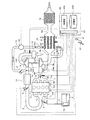
図1は、この実施例に係る内燃機関の全体構成図である。図1を用いて、この実施例に係る内燃機関の構成について説明する。この実施例に係る内燃機関1は、改質手段である改質器20に排ガスExの一部を導き、この排ガスExに炭化水素(HC)を含む燃料を供給することによって水素(H2)を生成する。そして、この改質反応によって得られた水素を含むガス(以下改質ガスという)Exrを内燃機関1に還流させる。
FIG. 1 is an overall configuration diagram of an internal combustion engine according to this embodiment. The configuration of the internal combustion engine according to this embodiment will be described with reference to FIG. The internal combustion engine 1 according to this embodiment introduces a part of the exhaust gas Ex to the
内燃機関1は、4個の気筒が直列に配置されているが、気筒数及び気筒配置はこれに限られるものではない。また、内燃機関1は、いわゆるロータリー式の内燃機関であってもよい。内燃機関1に供給される燃料Fは、燃料タンク70内のフィードポンプ71によってポート噴射弁6に供給される。そして、ポート噴射弁6から吸気通路3内に噴射され、吸気通路3を通る空気Aと混合気を形成する。この混合気は、インテークマニホールド71〜74を通って各気筒1s1〜1s4へ導入される。
Although the internal combustion engine 1 has four cylinders arranged in series, the number of cylinders and the cylinder arrangement are not limited to this. The internal combustion engine 1 may be a so-called rotary internal combustion engine. The fuel F supplied to the internal combustion engine 1 is supplied to the port injection valve 6 by a
この実施例においては、単独のポート噴射弁6により内燃機関1の各気筒へ燃料Fを供給するが、ポート噴射弁を気筒数分用意して、各気筒1s1〜1s4のインテークマニホールド71〜74へ燃料Fを噴射してもよい。また、ポート噴射弁の代わりに、気筒内へ直接燃料を噴射する、いわゆる直噴噴射弁を用いて、内燃機関1へ燃料Fを供給してもよい。さらに、ポート噴射弁と直噴噴射弁とを備え、内燃機関1の運転条件に応じて両者の燃料噴射割合を変更して、内燃機関1へ燃料を供給してもよい。 In this embodiment, the fuel F is supplied to each cylinder of the internal combustion engine 1 by the single port injection valve 6, but the port injection valves are prepared for the number of cylinders, and the intake manifold 7 1 of each cylinder 1 s 1 to 1 s 4 is prepared. to 7 4 fuel F may be injected into. Further, the fuel F may be supplied to the internal combustion engine 1 by using a so-called direct injection valve that directly injects fuel into the cylinder instead of the port injection valve. Furthermore, a port injection valve and a direct injection valve may be provided, and fuel may be supplied to the internal combustion engine 1 by changing the fuel injection ratio between the two according to the operating conditions of the internal combustion engine 1.
この実施例に係る内燃機関1は、過給手段を備える。過給手段としては、ターボチャージャー(以下ターボという)14を備え、空気Aを過給して内燃機関1へ供給する。ターボ14は、圧縮機14Cとタービン14Tとで構成されており、内燃機関1の排ガスExによりタービン14Tが駆動される。タービン14Tは、シャフト14Sを介して圧縮機14Cを駆動して、内燃機関1に空気Aを過給する。ターボ14は、排気バイパス通路9bに備えられた過給圧制御弁14wによって、過給圧が制御される。なお、過給手段としては、ターボ14の他にも、内燃機関1により駆動される、いわゆるスーパーチャージャーを用いることもできる。
The internal combustion engine 1 according to this embodiment includes supercharging means. As the supercharging means, a turbocharger (hereinafter referred to as turbo) 14 is provided, and the air A is supercharged and supplied to the internal combustion engine 1. The turbo 14 includes a
また、ターボ14で圧縮された空気Aは昇温するため、ターボ14と内燃機関1との間には、昇温した空気Aを冷却するための吸気冷却手段として、インタークーラー12が備えられている。ターボ14で圧縮された空気Aは、インタークーラー12で冷却された後、スロットル弁4を通って内燃機関1へ供給される。
Further, since the temperature of the air A compressed by the turbo 14 rises, an
内燃機関1に供給される空気Aは、吸気通路3の入口に取り付けられるエアクリーナ13でごみ等が除去されてから、ターボ14で過給されて内燃機関1へ送られる。内燃機関1へ供給される空気Aは、吸気通路3に設けられるスロットル弁4によって流量が調整される。スロットル弁4の開度は、アクセル17と連動する。この実施例において、アクセル17の開度はアクセル開度センサ47で検出されて、エンジンECU50に取り込まれる。アクセル開度センサ47からのアクセル開度情報を元に、エンジンECU50はスロットル弁4の開度を調整する。
The air A supplied to the internal combustion engine 1 is supercharged by the turbo 14 after being removed from the
アクセル開度が大きくなると、スロットル弁4の開度は大きくなり、アクセル開度が小さくなると、スロットル弁4の開度は小さくなる。内燃機関1へ供給される空気は、吸気通路3であってスロットル弁4の上流に設けられるエアフローセンサ42で流量が計測されて、その計測値はエンジンECU(Electronic Control Unit)50に取り込まれる。エンジンECU50は、エアフローセンサ42により計測された吸入空気量Gaと、回転数センサ43で計測される内燃機関1の機関回転数NEとから、内燃機関1に対する燃料噴射量Qfを決定する。
When the accelerator opening increases, the opening of the throttle valve 4 increases, and when the accelerator opening decreases, the opening of the throttle valve 4 decreases. The flow of air supplied to the internal combustion engine 1 is measured by an
内燃機関1の各気筒1s1〜1s4で燃焼した混合気は、排ガスExとなってエキゾーストマニホールド8へ排出される。この排ガスExは、第1排気通路9aを通ってターボ14へ導かれ、これを駆動する。ターボ14を駆動した排ガスExは、排気バイパス通路9bを通って改質器20の排気通路22へ導入され、排ガスExを改質するための熱を与える。改質器20から排出された排ガスExは、浄化触媒16で浄化された後、大気中へ放出される。なお、浄化触媒16は、改質器20と内燃機関1との間に配置してもよい。第1排気通路9aには、A/F(Air/Fuel:空燃比)センサ45が取り付けられており、排ガスExの空燃比を計測する。そして、排ガスExの空燃比から内燃機関1の燃焼状態を判定し、所定の空燃比から外れた場合には、エンジンECU50で決定される燃料噴射量を補正する。
The air-fuel mixture burned in each cylinder 1 s 1 to 1 s 4 of the internal combustion engine 1 becomes exhaust gas Ex and is discharged to the exhaust manifold 8. The exhaust gas Ex is guided to the turbo 14 through the first exhaust passage 9a and drives it. The exhaust gas Ex driving the turbo 14 is introduced into the
第2排気通路9cからは改質用導管11が分岐しており、改質用導管11は、改質器20の改質室21と接続されている。改質用導管11には改質用燃料噴射弁24が取り付けられており、この改質用燃料噴射弁24が、改質用導管11へ導かれた排ガスExへ改質用燃料Frを噴射する。改質用燃料噴射弁24には、燃料タンク70内のフィードポンプ71から燃料が供給される。
A reforming
改質器20は、改質室21と排気通路22とで構成される。改質室21の内壁面には改質用触媒が担持されており、排気通路22を流れる排ガスExの熱により改質用触媒が加熱されて、活性温度Ta以上に保持される。改質器20は、複数の改質室21を備え、各改質室21はそれぞれ連通しており、排ガスExと改質用燃料Frとの混合気(改質用混合気)Gmrは、改質室21を通過する間に改質される。ここで、改質用触媒には、例えばロジウム系の触媒が用いられる。
The
改質器20には、改質触媒の温度を測定するため、改質触媒床温度センサ44が取り付けられる。改質触媒そのものの温度を測定することは困難であるため、改質触媒を担持する触媒床の温度を測定して、改質触媒温度とする。改質触媒温度が低い場合、改質ガスExr中の水素濃度は低く、改質触媒温度が高くなるほど改質ガスExr中の水素濃度は高くなる。このため、改質触媒温度が活性温度Ta以上になってから、排ガスExの改質を開始するように、改質触媒床温度センサ44により改質触媒の温度を監視する。なお、ロジウム系の改質触媒を用いる場合、活性温度Taは600℃程度である。
A reforming catalyst bed temperature sensor 44 is attached to the
改質室21の出口21oには、改質室21と、吸気通路3とを接続する、ガス還流通路10が取り付けられている。ガス還流通路10は、排ガスEx又は改質ガスExrを、内燃機関1の吸気側、すなわち吸気通路3へ還流させる機能を持つ。この実施例において、ガス還流通路10は、ターボ14とインタークーラー12との間に接続されて、この部分に改質ガスExrを還流させる。このような構成により、インタークーラー12の上流(ターボ14側)へ改質ガスExrを還流させることができるので、高温の改質ガスExrを冷却して内燃機関1の気筒1s1〜1s4へ還流させることができる。また、インタークーラー12の上流へ改質ガスExrを還流させることにより、ターボ14で過給された空気Aと改質ガスExrとの混合を促進することができる。これにより、改質ガスExrをより冷却することができる。
A
これらの作用によって、内燃機関1の各気筒1s1〜1s4へ還流させる改質ガスExrと空気Aとの混合気体の体積効率を向上させることができるとともに、ノッキングが抑制できる。その結果、インタークーラー12で冷却をしなかった場合と比較して、改質器20に対して同一の燃料を供給した場合、ノッキングが改善されるため点火時期を進角させることができ、内燃機関の出力トルクが増加する。また、体積効率が向上するため、インタークーラー12で冷却をしなかった場合と比較して、より多くの改質ガスを還流させることができるので、燃料消費を抑制できる。
By these actions, the volumetric efficiency of the mixed gas of the reformed gas Exr and the air A that is recirculated to the cylinders 1s 1 to 1s 4 of the internal combustion engine 1 can be improved and knocking can be suppressed. As a result, when the same fuel is supplied to the
また、改質ガスExrの冷却手段をインタークーラー12で兼ねることができるので、改質ガスExrを冷却するための冷却手段を別個に設けなくてよい。これにより、改質のためのシステムを簡略化して信頼性を向上できるとともに、コストも低減できる。さらに、ターボ14の圧縮機14Cの下流(すなわちインタークーラー12側)に改質ガスExrを還流させるので、水素を含む改質ガスExrは圧縮機14Cで移動が妨げられる。これにより、エアクリーナ13から外部に漏れるおそれを極めて低減できる。また、改質ガスExrは、改質用混合気Gmrを改質したものなので、排ガスEx中の微細なカーボン等が残留しているおそれがある。この実施例の構成では、圧縮機14Cの下流に改質ガスExrを還流させるので、圧縮機14Cに対する前記残留物の影響を極小にできる。
Further, since the
改質器20と吸気通路3とを接続するガス還流通路10には、改質ガスExrを加圧して吸気通路3へ送る改質ガス加圧手段が設けられている。この実施例において、改質ガス化圧手段はポンプ15である。ポンプ15の駆動源は、内燃機関1であってもよいし、車載のバッテリーによってポンプ15を駆動してもよい。ターボ14で過給されると、空気Aの圧力は大気圧よりも大きくなる。このため、ターボ14による過給時に改質ガスExrを還流する場合、ポンプ15により改質ガスExrの圧力を、ターボ14の過給圧力よりも大きくして過給する。これにより、過給中であっても確実に改質ガスExrを吸気通路3へ還流させることができる。
The
なお、過給圧力が低いときや過給をしないときには、ポンプ15の吐出圧力を低くしたり、ポンプ15の動作を停止したりして、駆動ロスを低減してもよい。また、少なくともターボ14による過給中には、加圧手段であるポンプ15を作動させる。さらに、過給圧力が所定の圧力(例えば第2排気通路9c内の圧力)よりも低い場合には、改質ガス加圧手段であるポンプ15の動作を停止してもよい。このようにすれば、改質ガスExrを加圧圧送する必要がない場合には、ポンプ15の動作を停止できるので、ポンプ15による駆動ロスを低減できる。
Note that when the supercharging pressure is low or not supercharging, the discharge pressure of the
改質ガス加圧手段としては、改質器20の下流、例えば第3排気通路9dに絞り弁を設け、過給時に改質ガスExrを還流させる場合にはこの絞り弁を閉じる。これにより、改質用導管11内の圧力を上昇させることができるので、過給時においても吸気通路3へ改質ガスを還流させることができる。このとき、前記絞り弁の開度を調整することにより、改質ガスExrの圧力を調整してもよい。ガス還流通路10の出口10o近傍には、還流流量調整手段である還流流量調整弁5が設けられており、エンジンECU50からの指令で、吸気通路3へ還流させる改質ガスExrの流量を調整する。
As the reformed gas pressurizing means, a throttle valve is provided downstream of the
第3排気通路9から改質用導管11へ導かれた排ガスExは、改質用燃料噴射弁24から改質用燃料Frが噴射される。改質用燃料Frは、内燃機関1の各気筒1s1〜1s4へ供給される燃料Fの一部であり、内燃機関1の運転条件に応じて改質用燃料Frの噴射量Qfrが決定される。改質用燃料Frと排ガスExとの改質用混合気Gmrは、改質用導管11から改質室21へ導入され、改質室21の内壁面に担持された改質触媒により、式(1)に示す改質反応により改質されて改質ガスExrとなる。
1.56(7.6CO2+6.8H2O+40.8N2)+3C7.6H13.6+4122kJ→31H2+34.7CO+63.6N2・・・(1)
The exhaust gas Ex guided from the third exhaust passage 9 to the reforming
1.56 (7.6CO 2 + 6.8H 2 O + 40.8N 2) + 3C 7.6 H 13.6 + 4122kJ → 31H 2 + 34.7CO + 63.6N 2 ··· (1)
ここで、左辺第1項が排ガスEx、左辺第2項が燃料(炭化水素CHであり、この実施例ではガソリン)、右辺が改質ガスExrを示す。右辺の改質ガスExrに含まれる水素は、全改質ガスの体積に対して24vol%である。また、この改質反応は吸熱反応であり、これにより排ガスExの熱エネルギを回収することになる。このように、吸熱反応により排ガスExが改質されるため、内燃機関1に供給する燃料の量が同一であっても、排ガスExの熱を吸収した分だけ内燃機関1での燃焼における発熱量が増加する。 Here, the first term on the left side represents the exhaust gas Ex, the second term on the left side represents fuel (hydrocarbon CH, gasoline in this embodiment), and the right side represents the reformed gas Exr. Hydrogen contained in the reformed gas Exr on the right side is 24 vol% with respect to the total reformed gas volume. Further, this reforming reaction is an endothermic reaction, whereby the thermal energy of the exhaust gas Ex is recovered. Thus, since the exhaust gas Ex is reformed by the endothermic reaction, even if the amount of fuel supplied to the internal combustion engine 1 is the same, the amount of heat generated in the combustion in the internal combustion engine 1 by the amount absorbed by the heat of the exhaust gas Ex. Will increase.
また、水素(H2)の発熱量は241.7kJ/molであり、ガソリン(CH1.869)の発熱量は596.5kJ/molである。しかし、式(1)の改質反応により、3モルのガソリン(燃料)から31モルの水素が発生する。したがって、前記発熱量と、式(1)の改質によるモル数変化とを乗ずると、ガソリン単独を燃焼させる場合と比較して、改質ガスExrの発熱量は大幅に増加する。これにより、内燃機関1の出力トルクが増加し、また燃料消費は低減される。 The calorific value of hydrogen (H 2 ) is 241.7 kJ / mol, and the calorific value of gasoline (CH 1.869 ) is 596.5 kJ / mol. However, the reforming reaction of the formula (1) generates 31 moles of hydrogen from 3 moles of gasoline (fuel). Therefore, when the calorific value is multiplied by the change in the number of moles due to the reforming of the formula (1), the calorific value of the reformed gas Exr is significantly increased as compared with the case where gasoline alone is combusted. As a result, the output torque of the internal combustion engine 1 is increased and the fuel consumption is reduced.
改質室21で生成された改質ガスExrは、ガス還流通路10を通って、吸気通路3へ導入される。改質ガスExrは、700℃前後の高温になるため、吸気通路に設けられるインタークーラー12で冷却されてから、内燃機関1へ導入される。吸気通路3へ導入される改質ガスExrの流量(還流流量)は、還流流量調整弁5で制御される。吸気通路3へ導入される改質ガスExrの流量は、内燃機関1の運転条件に基づき、当該運転条件における最大限の改質ガスを内燃機関1に導入できるように決定されるが、その詳細については後述する。この場合、改質ガスExrに含まれる水素、一酸化炭素(CO)の量を考慮し、ポート噴射弁6の燃料噴射量を低減して空燃比A/Fを最適化する。
The reformed gas Exr generated in the reforming
改質ガスExrに含まれる水素(H2)は、ガソリンと比較して最大点火エネルギが1/10程度であり、最大燃焼速度が10倍弱である。このため、水素はガソリンと比較して急速燃焼する。上記改質反応によって得られた水素を含む改質ガスExrを内燃機関1に供給すると、改質ガスExr中の水素により、燃焼改善効果が得られる。内燃機関1の運転においては、排ガスExを吸気側に還流させる、いわゆるEGR(Exhaust Gas Recirculation)を実行することがある。 Hydrogen (H 2 ) contained in the reformed gas Exr has a maximum ignition energy of about 1/10 as compared with gasoline, and a maximum combustion rate is slightly less than 10 times. For this reason, hydrogen burns faster than gasoline. When the reformed gas Exr containing hydrogen obtained by the reforming reaction is supplied to the internal combustion engine 1, the combustion improvement effect is obtained by the hydrogen in the reformed gas Exr. In the operation of the internal combustion engine 1, so-called EGR (Exhaust Gas Recirculation), in which the exhaust gas Ex is recirculated to the intake side, may be executed.
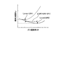
図2は、燃料消費率とガス還流率との関係を示す説明図である。ここでガス還流率とは、ガス還流量/(ガス還流量+吸入空気量)である。図2の点線は、排ガスExのみを吸気側に還流させた場合を示している。内燃機関1の運転中にEGRを実行すると、ポンプロスが低減されて燃料消費率を低減できる。ガス還流率(いわゆるEGR率と同義)を増加させると、ポンプロスの低減度合いも大きくなって燃料消費率が低下するが、あるガス還流率(ここではGR1)を境に燃料消費率は増加する。これは、ガス環流率が高くなると、気筒内に還流する排ガスExが増加するため、燃焼速度が遅くなって燃焼が悪化するためである。その結果、内燃機関1の出力トルクが低下するので、同じトルクを得ようとするとそれだけ多くの燃料を消費することになる。 FIG. 2 is an explanatory diagram showing the relationship between the fuel consumption rate and the gas recirculation rate. Here, the gas recirculation rate is gas recirculation amount / (gas recirculation amount + intake air amount). The dotted line in FIG. 2 shows the case where only the exhaust gas Ex is recirculated to the intake side. When EGR is executed during operation of the internal combustion engine 1, the pump loss is reduced and the fuel consumption rate can be reduced. When the gas recirculation rate (synonymous with the so-called EGR rate) is increased, the degree of reduction in pump loss increases and the fuel consumption rate decreases, but the fuel consumption rate increases at a certain gas recirculation rate (here, GR1). This is because when the gas recirculation rate increases, the exhaust gas Ex that recirculates in the cylinder increases, so that the combustion speed becomes slower and the combustion worsens. As a result, the output torque of the internal combustion engine 1 is reduced, and so much fuel is consumed to obtain the same torque.
図2の実線は、水素を含む改質ガスを吸気側に還流させた場合を示している。この実施例に係る内燃機関1は、水素を含む改質ガスExrを内燃機関1に還流させるので、図2に示すように、改質ガスExrの還流量を増加させた場合でも、水素が急速燃焼することで、燃焼悪化が抑制される。その結果、水素を含む改質ガスExrを還流させる場合には、排ガスExのみを還流させる場合と比較して、ガス還流率を大きくできる。これにより、ポンプロス低減による燃料消費率の低減効果を有効に発揮させることができる。なお、改質ガスExrの還流量増加にともなう燃焼悪化は、改質ガス中の水素が補うので、トルク低下によるドライバビリティ悪化も抑制される。また、改質ガスExrの還流量増加にともなう燃焼悪化を水素により抑制できるので、改質ガスExrの還流流量を多くして、燃焼室の温度を低下させ、ストイキ(λ=1)で運転できる領域を拡大できる。 The solid line in FIG. 2 shows the case where the reformed gas containing hydrogen is recirculated to the intake side. Since the internal combustion engine 1 according to this embodiment recirculates the reformed gas Exr containing hydrogen to the internal combustion engine 1, as shown in FIG. 2, even when the recirculation amount of the reformed gas Exr is increased, the hydrogen rapidly Combustion suppresses deterioration of combustion. As a result, when the reformed gas Exr containing hydrogen is recirculated, the gas recirculation rate can be increased as compared with the case where only the exhaust gas Ex is recirculated. Thereby, the reduction effect of the fuel consumption rate by pump loss reduction can be exhibited effectively. Note that the deterioration in combustion due to the increase in the recirculation amount of the reformed gas Exr is compensated for by hydrogen in the reformed gas, so that the drivability deterioration due to torque reduction is also suppressed. Further, since the deterioration of combustion accompanying the increase in the recirculation amount of the reformed gas Exr can be suppressed by hydrogen, the recirculation flow rate of the reformed gas Exr can be increased, the temperature of the combustion chamber can be lowered, and the operation can be performed with stoichiometry (λ = 1). The area can be expanded.
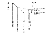
図3−1は、この実施例の構成における改質ガス温度の低下を示す説明図である。図3−2は、この実施例の構成における吸入ガス温度に対するトルク等を示す説明図である。両図とも、インタークーラー前導入時が、インタークーラー12とターボ14との間に改質ガスを還流させた構成であり、この実施例に係る内燃機関の構成である。インタークーラー後導入時は、インタークーラー12と内燃機関1との間に改質ガスを還流させた構成であり、この実施例の比較例に係る構成である。
FIG. 3A is an explanatory diagram showing a decrease in the reformed gas temperature in the configuration of this example. FIG. 3-2 is an explanatory diagram showing torque and the like with respect to the intake gas temperature in the configuration of this embodiment. In both figures, when the intercooler is introduced, the reformed gas is recirculated between the
図3−1から分かるように、還流流量調整弁5の後においては、この実施例の構成も比較例の構成も改質ガスExrの温度が同じ温度であるが、インタークーラー12後(下流)で比較すると、この実施例の構成の方が、改質ガスExrの温度は低下することが分かる。同様に、インテークマニホールド71〜74で比較すると、この実施例の構成の方が、改質ガスExrの温度は低下することが分かる。このように、この実施例に係る内燃機関1では、改質ガスExrの温度低下の効果が確認された。 As can be seen from FIG. 3A, after the reflux flow rate adjusting valve 5, the temperature of the reformed gas Exr is the same in both the configuration of this embodiment and the configuration of the comparative example, but after the intercooler 12 (downstream). By comparison, it can be seen that the temperature of the reformed gas Exr is lower in the configuration of this embodiment. Similarly, when compared with the intake manifold 7 1-7 4, towards the construction of this embodiment, the temperature of the reformed gas Exr it is found to decrease. Thus, in the internal combustion engine 1 according to this example, the effect of lowering the temperature of the reformed gas Exr was confirmed.
図3−2から分かるように、この実施例に係る構成の方が、比較例に係る構成よりも吸入ガス温度は低い。その結果、この実施例に係る構成の方が、比較例に係る構成よりも点火時期を進角でき、出力トルクも大きくなる。また、体積効率も高くなる。このように、この実施例に係る内燃機関1では、改質ガスExrの温度低下の効果により、性能向上が確認された。ここで、吸入ガスとは、改質ガスExrと空気との混合気体である。 As can be seen from FIG. 3-2, the configuration according to this example has a lower intake gas temperature than the configuration according to the comparative example. As a result, the configuration according to this embodiment can advance the ignition timing and the output torque is larger than the configuration according to the comparative example. In addition, volumetric efficiency is increased. Thus, in the internal combustion engine 1 according to this example, the performance improvement was confirmed by the effect of the temperature reduction of the reformed gas Exr. Here, the suction gas is a mixed gas of the reformed gas Exr and air.
(制御例)
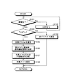
次に、この実施例に係る内燃機関1の運転制御例について説明する。この説明においては、適宜図1を参照されたい。図4は、この実施例に係る内燃機関の運転制御を説明するフローチャートである。この運転制御は、エンジンECU50の機能により実現できる。エンジンECU50が備えるI/P(Input/Output)ポート51には、エアフローセンサ42や回転数センサ43その他のセンサ類が接続されており、内燃機関1の運転に必要な情報をエンジンECU50が取得する。また、I/Pポート51には、還流流量調整弁5や改質用燃料噴射弁24その他の制御対象が接続されている。これらの制御対象は、前記センサ類から取得した情報に基づいてエンジンECU50の処理部50pが算出した制御パラメータに基づき制御される。また、エンジンECU50には、内燃機関1の運転制御に必要な制御マップ類や制御プログラムが格納されている。
(Control example)
Next, an example of operation control of the internal combustion engine 1 according to this embodiment will be described. In this description, please refer to FIG. 1 as appropriate. FIG. 4 is a flowchart for explaining the operation control of the internal combustion engine according to this embodiment. This operation control can be realized by the function of the
エンジンECU50の処理部50pは、冷却水温センサ46から内燃機関1の冷却水温を取得し、内燃機関1の暖機が完了したか否かを判定する(ステップS101)。内燃機関1の暖機が完了していない場合(ステップS101;No)、処理部50pはEGRを実行しない条件にあると判断して(ステップS102)、STARTに戻って内燃機関1の運転状態を監視する。EGRを実行すると、燃焼温度が低下するため、内燃機関1の暖機完了までに余分な時間を要するからである。
The
このとき、処理部50pは、還流流量調整弁5を閉じて改質器20側からのガスの還流を中止るとともに、改質用燃料噴射弁24からの燃料供給を停止して、内燃機関1の暖機が完了するまで改質を中止する。これにより、暖機中は、水素が不十分な改質ガスExrの還流を中止して燃焼を安定させるとともに、改質されない燃料が改質室21内やガス還流通路10内に付着することを抑制できる。その結果、これらに起因する燃料消費の増加を抑制できる。
At this time, the
内燃機関1の暖機が完了した場合(ステップS101;Yes)、処理部50pは、改質触媒床温度センサ44から改質触媒の温度を取得し、改質触媒の温度(以下改質触媒温度)Tcが、改質触媒の活性温度Ta以上であるか否かを判定する(ステップS103)。改質触媒温度Tcが活性温度Taよりも低い場合(ステップS103;No)、処理部50pは、改質しない排ガスEx、すなわち排ガスExのみを内燃機関1に還流させる条件であると判定する(ステップS104)。内燃機関1の暖機が完了していても、改質触媒温度Tcが活性温度Taよりも低い場合は、改質触媒は改質用燃料Frを十分に改質できず、十分な量の水素を含んだ改質ガスExrを内燃機関1へ還流できないからである。
When the warm-up of the internal combustion engine 1 is completed (step S101; Yes), the
このときには、内燃機関1の機関回転数NEと吸入空気量Gaとに対して予め定められた排ガスExのガス還流率(以下、第1のガス還流率という)に基づいて、排ガスExを内燃機関1の吸気通路へ還流する。このとき、処理部50pは、改質用燃料噴射弁24からの燃料供給を停止して、改質触媒の温度が活性温度以上になるまで改質を中止する。これにより、排ガスEx単独では改質されないので、還流流量調整弁5を介して排ガスExのみを吸気通路3へ還流させることができる。
At this time, the exhaust gas Ex is converted into the internal combustion engine based on the gas recirculation rate of the exhaust gas Ex (hereinafter referred to as the first gas recirculation rate) that is predetermined with respect to the engine speed NE and the intake air amount Ga of the internal combustion engine 1. It recirculates to 1 intake passage. At this time, the
排ガスExを還流させることにより、改質触媒の温度が活性温度以上になるまでの期間中は、排ガスExの還流によるポンピングロスの低減により燃料消費を低減できる。同時に、改質されない燃料が改質室21内やガス還流通路10内に付着することを抑制して、当該付着による燃料消費の悪化を抑制できる。
By recirculating the exhaust gas Ex, fuel consumption can be reduced by reducing the pumping loss due to the recirculation of the exhaust gas Ex during the period until the temperature of the reforming catalyst becomes equal to or higher than the activation temperature. At the same time, it is possible to suppress the unreformed fuel from adhering to the reforming
改質触媒の温度が活性温度Ta以上であると処理部50pが判定した場合(ステップS103;Yes)、処理部50pは、改質ガスExrを内燃機関1に還流させる条件であると判定する(ステップS105)。このときには、内燃機関1の機関回転数NEと吸入空気量Gaとに対して予め定められた改質ガスExrのガス還流率(以下、第2のガス還流率という)に基づいて、改質ガスExrを内燃機関1の吸気通路へ還流する。上述したように、改質ガスExrには水素が含まれているため、内燃機関1が同じ機関回転数NE、かつ同じ吸入空気量Gaで運転されているときには、排ガスExよりも改質ガスExrの方が内燃機関1への還流流量を大きくできる。すなわち、同じ機関回転数NE、かつ同じ吸入空気量Gaである場合には、第1のガス還流率>第2のガス還流率となる。
When the
処理部50pは、内燃機関1の回転数センサ43及びエアフローセンサ42から、内燃機関1の機関回転数NE及び吸入空気量Gaを取得する。そして、この機関回転数NE及び吸入空気量Gaに対応する第2のガス還流率を決定する。なお、内燃機関1の機関回転数NEと吸入空気量Gaとが決定されれば、そのときの改質触媒温度Tcも決まる。改質触媒温度Tcが決まれば、その改質触媒温度Tcにおいて得られる改質ガスExr中に含まれる水素濃度(改質ガス水素濃度)DH(vol%)も決まる。すなわち、内燃機関1の機関回転数NEと吸入空気量Gaとが決定されると、改質ガス水素濃度DHが決定される。
The
ある機関回転数NE、吸入空気量Gaが分かれば、内燃機関1が排出する総排ガス量が分かる。また、前記機関回転数NE、吸入空気量Gaのときにおける第2のガス還流率及びそのときの改質ガス水素濃度DHも分かるので、総排ガス量と改質器20に導入される排ガスExの量とが分かる。すなわち、第2のガス還流率に内燃機関1が排出する総排ガス量を乗じた値が、改質器20に導入される排ガスExの量である。そして、改質器20に導入される排ガスExの量と、改質ガス水素濃度DHとから、改質器20に供給する改質用燃料Frの量を決定できる。また、内燃機関1は、λ=1(ストイキ)で運転されているので、機関回転数NE、吸入空気量Gaが分かれば、内燃機関1に供給する総燃料供給量(内燃機関1及び改質器20に供給する燃料の総量)も分かる。上記手順によって、第2のガス還流率、内燃機関1に供給する燃料噴射量、改質器20に供給する改質用の燃料噴射量といった、改質ガスを還流させるにあたって必要な制御パラメータを決定することができる(ステップS106)。
If the engine speed NE and the intake air amount Ga are known, the total exhaust gas amount discharged from the internal combustion engine 1 can be known. In addition, since the second gas recirculation rate and the reformed gas hydrogen concentration DH at the time when the engine speed NE and the intake air amount Ga are known, the total exhaust gas amount and the exhaust gas Ex introduced into the
次に、処理部50pは、改質ガス加圧手段(この実施例ではポンプ15)の駆動条件を決定する。処理部50pは、内燃機関1の運転条件からターボ14による過給圧を決定する。この過給圧に基づいて、ポンプ15の吐出量や吐出圧力等の駆動条件を決定する(ステップS107)。このように、過給圧力に基づいて改質ガス加圧手段であるポンプ15を駆動するので、過剰にポンプ15が駆動されることはない。これによって、ポンプ15の駆動損失を低減することができる。上記手順によって、改質ガスを還流させるにあたって必要な制御パラメータ、及びポンプ15の駆動条件を決定したら、処理部50pは、これらの制御パラメータ及び駆動条件にしたがって、還流流量調整弁5、ポート噴射弁6等を駆動して、改質ガスExrを還流させる(ステップS108)。
Next, the
以上、この実施例によれば、過給機により加圧された空気を冷却する吸気冷却手段の上流へ改質ガスを還流させるので、高温の改質ガスを冷却して内燃機関の気筒へ還流させることができる。また、吸気冷却手段の上流へ改質ガスを還流させることにより、過給機で過給された空気と改質ガスとの混合を促進することができる。これにより、改質ガスをより冷却することができる。その結果、内燃機関の各気筒へ還流させる改質ガスと空気との混合気体の体積効率を向上させることができるとともに、ノッキングが抑制できる。そして、吸気冷却手段で冷却をしなかった場合と比較して、改質器に対して同一の燃料を供給した場合、ノッキングが改善されるため点火時期を進角させることができ、内燃機関の出力トルクが増加する。 As described above, according to this embodiment, since the reformed gas is recirculated to the upstream side of the intake air cooling means for cooling the air pressurized by the supercharger, the high-temperature reformed gas is cooled and recirculated to the cylinder of the internal combustion engine. Can be made. Further, by allowing the reformed gas to recirculate upstream of the intake air cooling means, it is possible to promote the mixing of the air supercharged by the supercharger and the reformed gas. Thereby, the reformed gas can be further cooled. As a result, the volumetric efficiency of the mixed gas of reformed gas and air that is recirculated to each cylinder of the internal combustion engine can be improved, and knocking can be suppressed. Compared with the case where the cooling is not performed by the intake air cooling means, when the same fuel is supplied to the reformer, the knocking is improved and the ignition timing can be advanced. Output torque increases.
また、改質ガスと空気との混合気体の冷却が促進される結果、体積効率が向上するため、吸気冷却手段で冷却をしなかった場合と比較して、より多くの改質ガスを還流させることができるので、燃料消費を抑制できる。さらに、改質ガスの冷却手段を吸気冷却手段で兼ねることができるので、改質ガスを冷却するための冷却手段を別個に設けなくてよい。これにより、改質のためのシステムを簡略化して信頼性を向上できるとともに、内燃機関のコストも低減できる。 Further, as a result of promoting the cooling of the mixed gas of reformed gas and air, the volumetric efficiency is improved, so that more reformed gas is recirculated as compared with the case where cooling is not performed by the intake air cooling means. As a result, fuel consumption can be suppressed. Furthermore, since the cooling means for the reformed gas can also serve as the intake air cooling means, it is not necessary to separately provide a cooling means for cooling the reformed gas. Thereby, the system for reforming can be simplified to improve the reliability, and the cost of the internal combustion engine can be reduced.
以上のように、本発明に係る内燃機関は、排ガスに燃料を供給して、水素を含む改質ガスを生成する内燃機関に有用であり、特に、さらに過給機を備える内燃機関に適している。 As described above, the internal combustion engine according to the present invention is useful for an internal combustion engine that supplies fuel to exhaust gas to generate reformed gas containing hydrogen, and is particularly suitable for an internal combustion engine that further includes a supercharger. Yes.
1 内燃機関
3 吸気通路
5 還流流量調整弁
10 ガス還流通路
11 改質用導管
12 インタークーラー
14 ターボ(ターボチャージャー)
14C 圧縮機
15 ポンプ
20 改質器
21 改質室
22 排気通路
24 改質用燃料噴射弁
50 エンジンECU
50p 処理部
DESCRIPTION OF SYMBOLS 1
50p processing section
Claims (5)
改質触媒により排ガスと燃料との混合気を改質して、水素を含む改質ガスを生成する改質手段と、
前記吸気通路に設けられるとともに、前記内燃機関に供給する空気を加圧する過給手段と、
前記吸気通路に設けられるとともに、前記過給手段から吐出される空気を冷却する吸気冷却手段と、
前記吸気通路であって、前記過給手段と前記吸気冷却手段との間に前記改質ガスを還流させるガス還流通路と、
を備えることを特徴とする内燃機関。 An internal combustion engine that is driven by combustion of a mixture of air and fuel supplied from an intake passage,
Reforming means for reforming a mixture of exhaust gas and fuel by a reforming catalyst to generate reformed gas containing hydrogen; and
A supercharging means provided in the intake passage and pressurizing air supplied to the internal combustion engine;
An intake air cooling means provided in the intake passage for cooling air discharged from the supercharging means;
A gas recirculation passage for recirculating the reformed gas between the supercharging means and the intake air cooling means;
An internal combustion engine comprising:
Priority Applications (1)
| Application Number | Priority Date | Filing Date | Title |
|---|---|---|---|
| JP2004214687A JP2006037745A (en) | 2004-07-22 | 2004-07-22 | Internal combustion engine |
Applications Claiming Priority (1)
| Application Number | Priority Date | Filing Date | Title |
|---|---|---|---|
| JP2004214687A JP2006037745A (en) | 2004-07-22 | 2004-07-22 | Internal combustion engine |
Publications (1)
| Publication Number | Publication Date |
|---|---|
| JP2006037745A true JP2006037745A (en) | 2006-02-09 |
Family
ID=35903005
Family Applications (1)
| Application Number | Title | Priority Date | Filing Date |
|---|---|---|---|
| JP2004214687A Pending JP2006037745A (en) | 2004-07-22 | 2004-07-22 | Internal combustion engine |
Country Status (1)
| Country | Link |
|---|---|
| JP (1) | JP2006037745A (en) |
Cited By (13)
| Publication number | Priority date | Publication date | Assignee | Title |
|---|---|---|---|---|
| KR100892538B1 (en) | 2007-12-15 | 2009-04-09 | 현대자동차주식회사 | Exhaust gas aftertreatment device for improving NOx storage performance during regeneration of diesel particulate filter |
| EP2048339A4 (en) * | 2006-08-04 | 2010-03-24 | Toyota Motor Co Ltd | INTERNAL COMBUSTION ENGINE |
| WO2010076967A3 (en) * | 2008-12-31 | 2010-08-19 | 연세대학교 산학협력단 | Harmful emissions reduction apparatus for engine using reformer, reformer for the same, and harmful emissions reduction method for engine using the same |
| JP2010242683A (en) * | 2009-04-08 | 2010-10-28 | Toyota Motor Corp | Exhaust gas reforming system |
| JP2011122532A (en) * | 2009-12-11 | 2011-06-23 | Mazda Motor Corp | Control device for engine with supercharger |
| EP2216537A4 (en) * | 2007-11-02 | 2011-07-27 | Toyota Motor Co Ltd | INTERNAL COMBUSTION ENGINE |
| GB2500598A (en) * | 2012-03-26 | 2013-10-02 | Ford Global Tech Llc | Engine system comprising EGR and oxygen delivery system |
| KR20180054269A (en) * | 2016-11-15 | 2018-05-24 | 현대자동차주식회사 | Reforming system and reformer operating method using temperature sensor |
| KR20180104529A (en) * | 2017-03-13 | 2018-09-21 | 현대자동차주식회사 | Control method for vehicle |
| US20180320641A1 (en) * | 2017-05-08 | 2018-11-08 | Hyundai Motor Company | Fuel reforming system |
| US10371104B2 (en) * | 2017-04-18 | 2019-08-06 | Hyundai Motor Company | Fuel reforming system and control method of coolant supply |
| US11746714B2 (en) | 2019-02-01 | 2023-09-05 | Ihi Corporation | Internal combustion engine system with temperature based output control |
| JP2023542821A (en) * | 2020-09-25 | 2023-10-12 | バクスター インターナショナル インコーポレイティッド | Parenteral nutritional preparations containing vitamin B12 |
-
2004
- 2004-07-22 JP JP2004214687A patent/JP2006037745A/en active Pending
Cited By (20)
| Publication number | Priority date | Publication date | Assignee | Title |
|---|---|---|---|---|
| EP2048339A4 (en) * | 2006-08-04 | 2010-03-24 | Toyota Motor Co Ltd | INTERNAL COMBUSTION ENGINE |
| US8607743B2 (en) | 2007-11-02 | 2013-12-17 | Toyota Jidosha Kabushiki Kaisha | Internal combustion engine |
| EP2216537A4 (en) * | 2007-11-02 | 2011-07-27 | Toyota Motor Co Ltd | INTERNAL COMBUSTION ENGINE |
| KR100892538B1 (en) | 2007-12-15 | 2009-04-09 | 현대자동차주식회사 | Exhaust gas aftertreatment device for improving NOx storage performance during regeneration of diesel particulate filter |
| WO2010076967A3 (en) * | 2008-12-31 | 2010-08-19 | 연세대학교 산학협력단 | Harmful emissions reduction apparatus for engine using reformer, reformer for the same, and harmful emissions reduction method for engine using the same |
| JP2010242683A (en) * | 2009-04-08 | 2010-10-28 | Toyota Motor Corp | Exhaust gas reforming system |
| JP2011122532A (en) * | 2009-12-11 | 2011-06-23 | Mazda Motor Corp | Control device for engine with supercharger |
| CN103362668B (en) * | 2012-03-26 | 2017-07-28 | 福特环球技术公司 | Method and apparatus for spraying oxygen in engine |
| CN103362668A (en) * | 2012-03-26 | 2013-10-23 | 福特环球技术公司 | Method and apparatus for injecting oxygen within an engine |
| US9181903B2 (en) | 2012-03-26 | 2015-11-10 | Ford Global Technologies, Llc | Method and apparatus for injecting oxygen within an engine |
| GB2500598A (en) * | 2012-03-26 | 2013-10-02 | Ford Global Tech Llc | Engine system comprising EGR and oxygen delivery system |
| GB2500598B (en) * | 2012-03-26 | 2017-12-20 | Ford Global Tech Llc | Method and apparatus for injecting oxygen within an engine |
| KR20180054269A (en) * | 2016-11-15 | 2018-05-24 | 현대자동차주식회사 | Reforming system and reformer operating method using temperature sensor |
| KR20180104529A (en) * | 2017-03-13 | 2018-09-21 | 현대자동차주식회사 | Control method for vehicle |
| KR102201276B1 (en) | 2017-03-13 | 2021-01-11 | 현대자동차주식회사 | Control method for vehicle |
| US10371104B2 (en) * | 2017-04-18 | 2019-08-06 | Hyundai Motor Company | Fuel reforming system and control method of coolant supply |
| US20180320641A1 (en) * | 2017-05-08 | 2018-11-08 | Hyundai Motor Company | Fuel reforming system |
| CN108869112A (en) * | 2017-05-08 | 2018-11-23 | 现代自动车株式会社 | Fuel reforming system |
| US11746714B2 (en) | 2019-02-01 | 2023-09-05 | Ihi Corporation | Internal combustion engine system with temperature based output control |
| JP2023542821A (en) * | 2020-09-25 | 2023-10-12 | バクスター インターナショナル インコーポレイティッド | Parenteral nutritional preparations containing vitamin B12 |
Similar Documents
| Publication | Publication Date | Title |
|---|---|---|
| JP4042649B2 (en) | Internal combustion engine | |
| CN103256127B (en) | For running the method from ignition internal combustion engine | |
| CN101680366A (en) | Internal combustion engine exhaust gas control system and control method of internal combustion engine exhaust gas control system | |
| KR101601157B1 (en) | Engine system having turbo charger and super charger | |
| US20100212611A1 (en) | Internal combustion engine | |
| JPWO2011145203A1 (en) | Internal combustion engine and control device for internal combustion engine | |
| US10968871B2 (en) | Engine system and method of controlling the same | |
| CN111486026B (en) | engine system | |
| CN103775251B (en) | Under rich condition, improve the exhaust gas recirculatioon of fuel economy | |
| JP2004156473A (en) | Control device for internal combustion engine having variable valve train | |
| JP2006233898A (en) | Egr device | |
| KR20190130093A (en) | Fuel injection control method of fuel reformer and fuel reforming system | |
| JP2020133634A (en) | Systems and methods for controlling the exhaust of spark-ignition internal combustion engines in automobiles | |
| JP5006805B2 (en) | Exhaust gas purification device for internal combustion engine | |
| JP2009270549A (en) | Exhaust emission control device for internal combustion engine | |
| JP4506335B2 (en) | Internal combustion engine and operation control device for internal combustion engine | |
| JP2006299890A (en) | Internal combustion engine | |
| JP2011001877A (en) | Internal combustion engine equipped with mechanical supercharger and supercharging method therefor | |
| JP4905385B2 (en) | Internal combustion engine with fuel reformer | |
| JP2014139425A (en) | Internal combustion engine | |
| JP4258388B2 (en) | Internal combustion engine and operation control device for internal combustion engine | |
| JP2013011198A (en) | Engine system | |
| JP2004353562A (en) | Dimethyl ether compression ignition engine | |
| JP2006046274A (en) | Internal combustion engine and operation control device for internal combustion engine | |
| US10767602B2 (en) | Engine system |