JP2006044366A - ショックアブソーバ取付構造 - Google Patents
ショックアブソーバ取付構造 Download PDFInfo
- Publication number
- JP2006044366A JP2006044366A JP2004225743A JP2004225743A JP2006044366A JP 2006044366 A JP2006044366 A JP 2006044366A JP 2004225743 A JP2004225743 A JP 2004225743A JP 2004225743 A JP2004225743 A JP 2004225743A JP 2006044366 A JP2006044366 A JP 2006044366A
- Authority
- JP
- Japan
- Prior art keywords
- shock absorber
- seat
- support shaft
- mounting structure
- shaft
- Prior art date
- Legal status (The legal status is an assumption and is not a legal conclusion. Google has not performed a legal analysis and makes no representation as to the accuracy of the status listed.)
- Granted
Links
Images


Landscapes
- Seats For Vehicles (AREA)
- Body Structure For Vehicles (AREA)
- Vehicle Body Suspensions (AREA)
Abstract
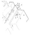
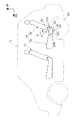
【解決手段】 ボルト58がリヤサイドメンバ44に形成された貫通孔48、50と、フロアパネル24に形成された貫通孔52とを挿通しており、ボルト58がリヤサイドメンバ44とフロアパネル24とに固定されている。ボルト58が挿通されたカラー56の車幅方向内側の突出部56Bが、ショックアブソーバ64の上端部64Aを取付ける部位となっていると共に、ボルト58が挿通されたカラー56の中間部56Aが、リヤシート14のフレーム固定解除手段30の取付部となるストライカ32となっている。
【選択図】 図1
Description
16 シートクッション
18 シートバック
22 シートクッションフレーム
24 フロアパネル
30 フレーム固定解除手段
32 ストライカ
44 リヤサイドメンバ
44A 車幅方向内側の縦壁部
44B 車幅方向外側の縦壁部
46 閉断面部
48 貫通孔
50 貫通孔
52 貫通孔
56 カラー
56A カラーの中間部
56B カラーの突出部
58 ボルト(支持軸)
60 ナット
64 ショックアブソーバ
69 車室
Claims (7)
- 車体に支持された支持軸にショックアブソーバを取付けるショックアブソーバ取付構造において、
前記支持軸の一部は乗員着座用シートを車体へ取付けるためのシート取付軸であり、前記ショックアブソーバを取付ける支持軸と前記シート取付軸とが共通であることを特徴とするショックアブソーバ取付構造。 - 対向する一対の壁部を有するサイドメンバを有し、前記支持軸が前記対向する一対の壁部を挿通しており、前記対向する一対の壁部の間に位置する前記支持軸の中間部が前記シート取付軸であって、前記対向する一対の壁部の一方から突出した前記支持軸の突出部に前記ショックアブソーバが取付けられていることを特徴とする請求項1に記載のショックアブソーバ取付構造。
- 前記支持軸の中間部が、前記支持軸の突出部より車幅方向外側にあることを特徴とする請求項2に記載のショックアブソーバ取付構造。
- 前記支持軸の突出部を支持する縦壁部が形成されたフロアパネルを有することを特徴とする請求項3に記載のショックアブソーバ取付構造。
- 前記フロアパネルの縦壁部は、前記シートの下方に形成した物入れ部の縦壁部であることを特徴とする請求項4に記載のショックアブソーバ取付構造。
- 前記シートはシートの前部又はシートの後部が前記シート取付軸に対して着脱可能となっていることを特徴とする請求項1〜5の何れか1項に記載のショックアブソーバ取付構造。
- 前記支持軸における前記ショックアブソーバを取付ける部位は車室の外側に配設されており、前記シート取付軸は車室の内側に連通した部位に配設されていることを特徴とする請求項1に記載のショックアブソーバ取付構造。
Priority Applications (1)
| Application Number | Priority Date | Filing Date | Title |
|---|---|---|---|
| JP2004225743A JP4258451B2 (ja) | 2004-08-02 | 2004-08-02 | ショックアブソーバ取付構造 |
Applications Claiming Priority (1)
| Application Number | Priority Date | Filing Date | Title |
|---|---|---|---|
| JP2004225743A JP4258451B2 (ja) | 2004-08-02 | 2004-08-02 | ショックアブソーバ取付構造 |
Publications (2)
| Publication Number | Publication Date |
|---|---|
| JP2006044366A true JP2006044366A (ja) | 2006-02-16 |
| JP4258451B2 JP4258451B2 (ja) | 2009-04-30 |
Family
ID=36023439
Family Applications (1)
| Application Number | Title | Priority Date | Filing Date |
|---|---|---|---|
| JP2004225743A Expired - Fee Related JP4258451B2 (ja) | 2004-08-02 | 2004-08-02 | ショックアブソーバ取付構造 |
Country Status (1)
| Country | Link |
|---|---|
| JP (1) | JP4258451B2 (ja) |
Cited By (4)
| Publication number | Priority date | Publication date | Assignee | Title |
|---|---|---|---|---|
| GB2484792A (en) * | 2010-10-19 | 2012-04-25 | Gm Global Tech Operations Inc | Vehicle with axle supported suspension under rear seat |
| GB2484798A (en) * | 2010-10-19 | 2012-04-25 | Gm Global Tech Operations Inc | Motor vehicle rear floor structure |
| WO2013045860A1 (fr) * | 2011-09-30 | 2013-04-04 | Renault S.A.S. | Bac de roue de secours et methode d'installation dudit bac en relation avec l'ancrage des amortisseurs |
| FR2980760A1 (fr) * | 2011-09-30 | 2013-04-05 | Renault Sa | Plancher en creux et methode d'installation |
-
2004
- 2004-08-02 JP JP2004225743A patent/JP4258451B2/ja not_active Expired - Fee Related
Cited By (8)
| Publication number | Priority date | Publication date | Assignee | Title |
|---|---|---|---|---|
| GB2484792A (en) * | 2010-10-19 | 2012-04-25 | Gm Global Tech Operations Inc | Vehicle with axle supported suspension under rear seat |
| GB2484798A (en) * | 2010-10-19 | 2012-04-25 | Gm Global Tech Operations Inc | Motor vehicle rear floor structure |
| US8528967B2 (en) | 2010-10-19 | 2013-09-10 | GM Global Technology Operations LLC | Rear floor structure for a motor vehicle |
| US8764035B2 (en) | 2010-10-19 | 2014-07-01 | GM Global Technology Operations LLC | Motor vehicle |
| GB2484792B (en) * | 2010-10-19 | 2017-06-28 | Gm Global Tech Operations Llc | Motor vehicle with suspension under rear seat |
| WO2013045860A1 (fr) * | 2011-09-30 | 2013-04-04 | Renault S.A.S. | Bac de roue de secours et methode d'installation dudit bac en relation avec l'ancrage des amortisseurs |
| FR2980760A1 (fr) * | 2011-09-30 | 2013-04-05 | Renault Sa | Plancher en creux et methode d'installation |
| WO2013057403A1 (fr) * | 2011-09-30 | 2013-04-25 | Renault S.A.S. | Plancher de véhicule en creux et methode d'installation en relation avec les amortisseurs |
Also Published As
| Publication number | Publication date |
|---|---|
| JP4258451B2 (ja) | 2009-04-30 |
Similar Documents
| Publication | Publication Date | Title |
|---|---|---|
| JP3866415B2 (ja) | 車体構造 | |
| JP4774976B2 (ja) | 車両の後部車体構造 | |
| JP5493898B2 (ja) | 車両のシート取付構造 | |
| JP4258451B2 (ja) | ショックアブソーバ取付構造 | |
| WO2007083414A1 (ja) | 車両の乗降用ステップ取付構造 | |
| JP4478662B2 (ja) | 車体後部構造 | |
| JP6057157B2 (ja) | シートバックのヒンジ構造 | |
| JP5035836B2 (ja) | キャブ | |
| JP4015085B2 (ja) | 車両用リヤサスペンション支持部構造の組立方法 | |
| JP4005548B2 (ja) | 車両の後部構造 | |
| JP2004237766A (ja) | 車両のガス燃料タンク取付構造 | |
| JP2019172074A (ja) | 車両のシート取付構造 | |
| JP7392371B2 (ja) | 車両の下部車体構造 | |
| JP2006088785A (ja) | 車両の後部車体構造 | |
| JP3889740B2 (ja) | 車両の後部構造 | |
| JP2565162Y2 (ja) | サスペンションサポートタワーの補強構造 | |
| JP5256983B2 (ja) | 自動車のフードストッパ構造 | |
| JP5863509B2 (ja) | 車両用シート装置 | |
| JP7543873B2 (ja) | 車両の荷室構造 | |
| JP4811096B2 (ja) | 車体後部構造 | |
| JP7395930B2 (ja) | 車両の下部車体構造 | |
| JP2005081954A (ja) | 自動車の車体前部構造 | |
| JP4967327B2 (ja) | 車両のシート配設構造 | |
| JP4005821B2 (ja) | 車両用リアシートのセンターヒンジ構造 | |
| JP2024153357A (ja) | 乗物用シート |
Legal Events
| Date | Code | Title | Description |
|---|---|---|---|
| A621 | Written request for application examination |
Free format text: JAPANESE INTERMEDIATE CODE: A621 Effective date: 20061010 |
|
| TRDD | Decision of grant or rejection written | ||
| A01 | Written decision to grant a patent or to grant a registration (utility model) |
Free format text: JAPANESE INTERMEDIATE CODE: A01 Effective date: 20090113 |
|
| A01 | Written decision to grant a patent or to grant a registration (utility model) |
Free format text: JAPANESE INTERMEDIATE CODE: A01 |
|
| A61 | First payment of annual fees (during grant procedure) |
Free format text: JAPANESE INTERMEDIATE CODE: A61 Effective date: 20090126 |
|
| FPAY | Renewal fee payment (event date is renewal date of database) |
Free format text: PAYMENT UNTIL: 20120220 Year of fee payment: 3 |
|
| FPAY | Renewal fee payment (event date is renewal date of database) |
Free format text: PAYMENT UNTIL: 20120220 Year of fee payment: 3 |
|
| FPAY | Renewal fee payment (event date is renewal date of database) |
Free format text: PAYMENT UNTIL: 20120220 Year of fee payment: 3 |
|
| FPAY | Renewal fee payment (event date is renewal date of database) |
Free format text: PAYMENT UNTIL: 20130220 Year of fee payment: 4 |
|
| FPAY | Renewal fee payment (event date is renewal date of database) |
Free format text: PAYMENT UNTIL: 20130220 Year of fee payment: 4 |
|
| FPAY | Renewal fee payment (event date is renewal date of database) |
Free format text: PAYMENT UNTIL: 20140220 Year of fee payment: 5 |
|
| LAPS | Cancellation because of no payment of annual fees |