JP2006061237A - Display stand - Google Patents
Display stand Download PDFInfo
- Publication number
- JP2006061237A JP2006061237A JP2004244633A JP2004244633A JP2006061237A JP 2006061237 A JP2006061237 A JP 2006061237A JP 2004244633 A JP2004244633 A JP 2004244633A JP 2004244633 A JP2004244633 A JP 2004244633A JP 2006061237 A JP2006061237 A JP 2006061237A
- Authority
- JP
- Japan
- Prior art keywords
- shelf
- piece
- plate
- panel
- side plate
- Prior art date
- Legal status (The legal status is an assumption and is not a legal conclusion. Google has not performed a legal analysis and makes no representation as to the accuracy of the status listed.)
- Granted
Links
- 238000003780 insertion Methods 0.000 abstract description 6
- 230000037431 insertion Effects 0.000 abstract description 6
- 239000002537 cosmetic Substances 0.000 description 4
- 238000004519 manufacturing process Methods 0.000 description 2
- 238000000034 method Methods 0.000 description 1
Images

Landscapes
- Display Racks (AREA)
Abstract
Description
この発明は、上下に配置された複数の棚段に商品をセットして陳列する厚紙製の陳列棚に関するものである。 The present invention relates to a cardboard display shelf for setting and displaying products on a plurality of shelves arranged vertically.
化粧品等の商品を店頭で陳列する吊下式の陳列棚として、下記特許文献1には、図4に示すようなものが記載されている。この陳列棚は、複数の棚段51を上下に配置し、各棚段51の前板52に一対の側板53を連設し、各側板53の後縁から延出した背板54を貼り合わせて形成される。
As a hanging-type display shelf for displaying products such as cosmetics at a storefront, the following
各棚段51では、側板53の下縁から延出した底片55を内側へ折り曲げ、前板52の下縁から延出した底板56を後方へ折り曲げ、その先端部の背当片57を上方へ折り曲げて、背板54の前面に沿わせるようにしている。
In each
各棚段51には棚台58がセットされ、この棚台58は、多数の商品保持穴59を有する棚板60の周縁に脚片61を連設し、これらの脚片61を下方へ折り曲げたものとされている。そして、商品の陳列に際しては、商品保持穴59に化粧品等の商品を挿入し、背板54の上部の紐穴63に紐を挿通して、この紐により陳列棚を吊り下げる。
A
しかしながら、上記のような陳列棚では、陳列時に商品の荷重が作用すると、各棚段が底抜けする恐れがある。 However, in the display shelf as described above, there is a risk that each shelf level may go through the bottom if a product load acts upon display.
また、製造時に貼り加工や棚台の製作が必要となるので、コストがかかり、店頭での組み立てに手間がかかるという問題もある。 In addition, since it is necessary to perform pasting and production of shelves at the time of manufacture, there is a problem that costs are increased and it takes time to assemble at the store.
そこで、この発明は、組み立てが簡単で、強度に優れ、低コストで提供できる厚紙製の陳列具を提供することを課題とする。 Accordingly, an object of the present invention is to provide a cardboard display device that is easy to assemble, has excellent strength, and can be provided at low cost.
上記課題を解決するため、この発明では、複数の棚段を上下に配置し、各棚段の前板に一対の側板を連設し、側板に背板を連設した陳列棚において、棚段をなす前板の上縁から棚板を延出し、棚板の両側縁と側板とを折込片を介して繋ぎ、折込片と側板の境界を後上がり45°の斜折線とし、一方の側板から延出した背板の先端に差込片を設け、他方の側板から継代を延出して、継代の基部にスリットを形成し、折込片と棚板の境界を谷折りしつつ、折込片を側板の内側に折り込み、継代に背板を重ね、スリットに差込片を差し込むようにしたのである。 In order to solve the above problems, in the present invention, in a display shelf in which a plurality of shelves are arranged up and down, a pair of side plates are connected to the front plate of each shelf, and a back plate is connected to the side plates. Extend the shelf from the upper edge of the front plate, connect both side edges of the shelf and the side plate via folding pieces, and make the boundary between the folded piece and the side plate a 45 ° diagonal fold line, and from one side plate Inserting piece at the tip of the extended back plate, extending the passage from the other side plate, forming a slit at the base of the passage, folding the boundary between the folding piece and the shelf, Was folded inside the side plate, the back plate was overlapped at the passage, and the insertion piece was inserted into the slit.
この発明に係る陳列棚は、前板から両側板を折り曲げると、折込片が斜折線に沿って折り込まれ、棚板が水平となって棚段が形成されるので、扁平な状態から簡単に組み立てることができ、貼り加工や棚台も不要であり、低コストで提供できる。また、この組立状態において、棚板が折込片を介し側板から吊り下げられた状態となるので、棚段は底抜けの恐れがなく、形状が安定し、強度に優れたものとなる。 The display shelf according to the present invention is easily assembled from a flat state because when the both side plates are folded from the front plate, the folding pieces are folded along the diagonal lines, and the shelf plate is horizontal to form a shelf step. In addition, pasting and shelves are unnecessary and can be provided at low cost. Further, in this assembled state, the shelf plate is suspended from the side plate via the folded piece, so that the shelf step does not have a possibility of bottom-out, the shape is stable, and the strength is excellent.
以下、この発明の実施形態を添付図面に基づいて説明する。 Embodiments of the present invention will be described below with reference to the accompanying drawings.
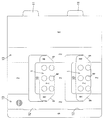
この陳列棚は、図1に示すような段ボール製のブランクから形成される。このブランクでは、棚段1をなす部分が上下2段に配置されており、各棚段1とその上方に位置する前板2の両側縁には側板3が連設され、一方の側板3の外縁には背板4が、他方の側板3の外縁には継代5がそれぞれ連設されている。
This display shelf is formed from a blank made of cardboard as shown in FIG. In this blank, the portion forming the
棚段1をなす前板2の上縁には、複数個の商品保持穴6を有する棚板7が連設され、棚板7の両側縁と側板3とは折込片8を介して繋がれて、折込片8と側板3の境界は、外側へかけて上方へ45°傾いた斜折線9とされている。また、棚板7の上縁には背当片10が連設されている。
A
さらに、背板4の外縁には、上下に2個の差込片11が設けられ、継代5の基部には、差込片11に対応して、上下2ヶ所にスリット12が形成されている。そのほか、側板3の上部には紐穴13が設けられている。
Further, two
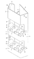
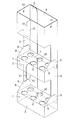
このブランクを組み立てるには、図2に示すように、前板2、一対の側板3及び背板4を角筒状に折り曲げ、折込片8と棚板7の境界を谷折りしつつ、折込片8を側板3の内側に折り込み、図3に示すように、背当片10を下方へ折り曲げて背板4の前面に沿わせ、継代5に背板4を重ね、スリット12に差込片11を差し込む。
To assemble this blank, as shown in FIG. 2, the
このとき、前板2から両側板3を折り曲げると、折込片8が斜折線9に沿って折り込まれ、棚板7が水平となって棚段1が形成されるので、この陳列具は、扁平な状態から簡単に組み立てることができる。
At this time, when the both
そして、このように組み立てた陳列棚を用いて店頭で商品を陳列する際には、各棚段1の商品保持穴6にチューブ入り化粧品等の商品を挿入し、紐穴13に紐を挿通して、この紐により陳列用什器のバー等に陳列棚を吊り下げる。
When products are displayed at the store using the display shelves assembled in this way, products such as cosmetics with tubes are inserted into the
この陳列状態においては、棚板7が折込片8を介し側板3から吊り下げられた状態となるので、棚段1は底抜けする恐れがなく、陳列棚全体の形状が安定し、荷重に対する強度にも優れたものとなる。
In this display state, since the
また、この陳列棚は、継代5の基部に形成したスリット12に、背板4の先端に設けた差込片11を差し込んで保形するので、背板4の貼り付けが不要となり、低コストで化粧品メーカー等の使用者に提供できる。
In addition, since the display shelf holds the shape by inserting the
1 棚段
2 前板
3 側板
4 背板
5 継代
6 商品保持穴
7 棚板
8 折込片
9 斜折線
10 背当片
11 差込片
12 スリット
13 紐穴
DESCRIPTION OF
Claims (1)
Priority Applications (1)
| Application Number | Priority Date | Filing Date | Title |
|---|---|---|---|
| JP2004244633A JP4658247B2 (en) | 2004-08-25 | 2004-08-25 | Display shelf |
Applications Claiming Priority (1)
| Application Number | Priority Date | Filing Date | Title |
|---|---|---|---|
| JP2004244633A JP4658247B2 (en) | 2004-08-25 | 2004-08-25 | Display shelf |
Publications (2)
| Publication Number | Publication Date |
|---|---|
| JP2006061237A true JP2006061237A (en) | 2006-03-09 |
| JP4658247B2 JP4658247B2 (en) | 2011-03-23 |
Family
ID=36108220
Family Applications (1)
| Application Number | Title | Priority Date | Filing Date |
|---|---|---|---|
| JP2004244633A Expired - Fee Related JP4658247B2 (en) | 2004-08-25 | 2004-08-25 | Display shelf |
Country Status (1)
| Country | Link |
|---|---|
| JP (1) | JP4658247B2 (en) |
Cited By (1)
| Publication number | Priority date | Publication date | Assignee | Title |
|---|---|---|---|---|
| JP2011083468A (en) * | 2009-10-16 | 2011-04-28 | Dainippon Printing Co Ltd | Hanger display rack |
Citations (3)
| Publication number | Priority date | Publication date | Assignee | Title |
|---|---|---|---|---|
| JPS452432Y1 (en) * | 1965-11-22 | 1970-01-31 | ||
| JP2001218658A (en) * | 2000-02-08 | 2001-08-14 | Rengo Co Ltd | Commodity display utensil |
| JP2003245177A (en) * | 2002-02-25 | 2003-09-02 | Morinaga & Co Ltd | Spoon or straw holder |
-
2004
- 2004-08-25 JP JP2004244633A patent/JP4658247B2/en not_active Expired - Fee Related
Patent Citations (3)
| Publication number | Priority date | Publication date | Assignee | Title |
|---|---|---|---|---|
| JPS452432Y1 (en) * | 1965-11-22 | 1970-01-31 | ||
| JP2001218658A (en) * | 2000-02-08 | 2001-08-14 | Rengo Co Ltd | Commodity display utensil |
| JP2003245177A (en) * | 2002-02-25 | 2003-09-02 | Morinaga & Co Ltd | Spoon or straw holder |
Cited By (1)
| Publication number | Priority date | Publication date | Assignee | Title |
|---|---|---|---|---|
| JP2011083468A (en) * | 2009-10-16 | 2011-04-28 | Dainippon Printing Co Ltd | Hanger display rack |
Also Published As
| Publication number | Publication date |
|---|---|
| JP4658247B2 (en) | 2011-03-23 |
Similar Documents
| Publication | Publication Date | Title |
|---|---|---|
| DE502004004783D1 (en) | Shelf made of a bendable material such as cardboard | |
| US20080083682A1 (en) | Display stand merchandise tray | |
| USD493309S1 (en) | Display stand merchandise tray | |
| CN201977329U (en) | A foldable display stand that is convenient to fold | |
| JP4658247B2 (en) | Display shelf | |
| JP2008308172A (en) | Packaging box | |
| JP5333927B2 (en) | Display stand with variable height display board | |
| CN208064950U (en) | A kind of showing stand | |
| JP3195952U (en) | Folding display rack | |
| JP4684457B2 (en) | Hanging display rack | |
| JP3195082U (en) | Folding display rack | |
| CN213650197U (en) | High resistance to compression corrugated paper box | |
| JP3251931B2 (en) | Foldable product display shelf | |
| JP3181553U (en) | Paper sheet stand | |
| JP5364538B2 (en) | Packaging container and blank sheet | |
| JP4806245B2 (en) | Product display | |
| JP2009018105A (en) | Display rack | |
| JP3242888U (en) | furniture | |
| CN207060637U (en) | A kind of paper structure product collet | |
| JP2001218658A (en) | Commodity display utensil | |
| JP4125049B2 (en) | Assembling display stand | |
| JP2003159164A (en) | Display stand | |
| JP2006337411A (en) | Connecting type display box | |
| JP2014150939A (en) | Card stand with solid edge frame | |
| JP3623199B2 (en) | Product display stand |
Legal Events
| Date | Code | Title | Description |
|---|---|---|---|
| A621 | Written request for application examination |
Effective date: 20070702 Free format text: JAPANESE INTERMEDIATE CODE: A621 |
|
| A977 | Report on retrieval |
Effective date: 20100727 Free format text: JAPANESE INTERMEDIATE CODE: A971007 |
|
| A131 | Notification of reasons for refusal |
Free format text: JAPANESE INTERMEDIATE CODE: A131 Effective date: 20100817 |
|
| A521 | Written amendment |
Free format text: JAPANESE INTERMEDIATE CODE: A523 Effective date: 20100903 |
|
| TRDD | Decision of grant or rejection written | ||
| A01 | Written decision to grant a patent or to grant a registration (utility model) |
Effective date: 20101207 Free format text: JAPANESE INTERMEDIATE CODE: A01 |
|
| A01 | Written decision to grant a patent or to grant a registration (utility model) |
Free format text: JAPANESE INTERMEDIATE CODE: A01 |
|
| A61 | First payment of annual fees (during grant procedure) |
Free format text: JAPANESE INTERMEDIATE CODE: A61 Effective date: 20101223 |
|
| FPAY | Renewal fee payment (prs date is renewal date of database) |
Free format text: PAYMENT UNTIL: 20140107 Year of fee payment: 3 |
|
| R150 | Certificate of patent (=grant) or registration of utility model |
Free format text: JAPANESE INTERMEDIATE CODE: R150 |
|
| FPAY | Renewal fee payment (prs date is renewal date of database) |
Free format text: PAYMENT UNTIL: 20140107 Year of fee payment: 3 |
|
| LAPS | Cancellation because of no payment of annual fees |