JP2006064201A - 熱交換器のヘッダタンク及び熱交換器のヘッダタンクと冷媒流通配管との接続構造 - Google Patents
熱交換器のヘッダタンク及び熱交換器のヘッダタンクと冷媒流通配管との接続構造 Download PDFInfo
- Publication number
- JP2006064201A JP2006064201A JP2004244088A JP2004244088A JP2006064201A JP 2006064201 A JP2006064201 A JP 2006064201A JP 2004244088 A JP2004244088 A JP 2004244088A JP 2004244088 A JP2004244088 A JP 2004244088A JP 2006064201 A JP2006064201 A JP 2006064201A
- Authority
- JP
- Japan
- Prior art keywords
- tank
- heat exchanger
- refrigerant
- pipe
- header tank
- Prior art date
- Legal status (The legal status is an assumption and is not a legal conclusion. Google has not performed a legal analysis and makes no representation as to the accuracy of the status listed.)
- Granted
Links
Images






Classifications
-
- F—MECHANICAL ENGINEERING; LIGHTING; HEATING; WEAPONS; BLASTING
- F28—HEAT EXCHANGE IN GENERAL
- F28D—HEAT-EXCHANGE APPARATUS, NOT PROVIDED FOR IN ANOTHER SUBCLASS, IN WHICH THE HEAT-EXCHANGE MEDIA DO NOT COME INTO DIRECT CONTACT
- F28D1/00—Heat-exchange apparatus having stationary conduit assemblies for one heat-exchange medium only, the media being in contact with different sides of the conduit wall, in which the other heat-exchange medium is a large body of fluid, e.g. domestic or motor car radiators
- F28D1/02—Heat-exchange apparatus having stationary conduit assemblies for one heat-exchange medium only, the media being in contact with different sides of the conduit wall, in which the other heat-exchange medium is a large body of fluid, e.g. domestic or motor car radiators with heat-exchange conduits immersed in the body of fluid
- F28D1/04—Heat-exchange apparatus having stationary conduit assemblies for one heat-exchange medium only, the media being in contact with different sides of the conduit wall, in which the other heat-exchange medium is a large body of fluid, e.g. domestic or motor car radiators with heat-exchange conduits immersed in the body of fluid with tubular conduits
- F28D1/053—Heat-exchange apparatus having stationary conduit assemblies for one heat-exchange medium only, the media being in contact with different sides of the conduit wall, in which the other heat-exchange medium is a large body of fluid, e.g. domestic or motor car radiators with heat-exchange conduits immersed in the body of fluid with tubular conduits the conduits being straight
- F28D1/0535—Heat-exchange apparatus having stationary conduit assemblies for one heat-exchange medium only, the media being in contact with different sides of the conduit wall, in which the other heat-exchange medium is a large body of fluid, e.g. domestic or motor car radiators with heat-exchange conduits immersed in the body of fluid with tubular conduits the conduits being straight the conduits having a non-circular cross-section
- F28D1/05366—Assemblies of conduits connected to common headers, e.g. core type radiators
- F28D1/05375—Assemblies of conduits connected to common headers, e.g. core type radiators with particular pattern of flow, e.g. change of flow direction
-
- F—MECHANICAL ENGINEERING; LIGHTING; HEATING; WEAPONS; BLASTING
- F28—HEAT EXCHANGE IN GENERAL
- F28F—DETAILS OF HEAT-EXCHANGE AND HEAT-TRANSFER APPARATUS, OF GENERAL APPLICATION
- F28F9/00—Casings; Header boxes; Auxiliary supports for elements; Auxiliary members within casings
- F28F9/02—Header boxes; End plates
- F28F9/0202—Header boxes having their inner space divided by partitions
- F28F9/0204—Header boxes having their inner space divided by partitions for elongated header box, e.g. with transversal and longitudinal partitions
-
- F—MECHANICAL ENGINEERING; LIGHTING; HEATING; WEAPONS; BLASTING
- F28—HEAT EXCHANGE IN GENERAL
- F28F—DETAILS OF HEAT-EXCHANGE AND HEAT-TRANSFER APPARATUS, OF GENERAL APPLICATION
- F28F9/00—Casings; Header boxes; Auxiliary supports for elements; Auxiliary members within casings
- F28F9/02—Header boxes; End plates
- F28F9/0219—Arrangements for sealing end plates into casing or header box; Header box sub-elements
- F28F9/0224—Header boxes formed by sealing end plates into covers
-
- F—MECHANICAL ENGINEERING; LIGHTING; HEATING; WEAPONS; BLASTING
- F28—HEAT EXCHANGE IN GENERAL
- F28F—DETAILS OF HEAT-EXCHANGE AND HEAT-TRANSFER APPARATUS, OF GENERAL APPLICATION
- F28F9/00—Casings; Header boxes; Auxiliary supports for elements; Auxiliary members within casings
- F28F9/02—Header boxes; End plates
- F28F9/0246—Arrangements for connecting header boxes with flow lines
Landscapes
- Engineering & Computer Science (AREA)
- Physics & Mathematics (AREA)
- Thermal Sciences (AREA)
- Mechanical Engineering (AREA)
- General Engineering & Computer Science (AREA)
- Heat-Exchange Devices With Radiators And Conduit Assemblies (AREA)
- Details Of Heat-Exchange And Heat-Transfer (AREA)
Abstract
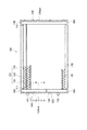
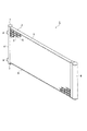
【解決手段】ヘッダタンク140を、流通路124が形成されるタンク部121と、チューブ110の端部111が挿入されるチューブ挿入孔122aを有するプレート部122とで構成し、タンク部121のチューブ挿入孔122aと対向しない部分に、プレート部122と接触してタンク部121の流通路124を2つ以上に仕切る仕切部126を設け、またタンク部121のチューブ挿入孔122aと対向する部分に、タンク部121の2つ以上の流通路124と連通する連通部125を設けたことを特徴とする。
【選択図】 図1
Description
a−2t < b < a
となるように各部の寸法を設定している。これによって、チューブ110をプレート部122のチューブ挿入孔122aに挿入したときに、タンク部121の端部断面121aにチューブ110の端部111の両端部分を確実に当接させることができる。
101…コア部
110…チューブ
111…(チューブ)端部
120…フィン
121…タンク部
121a…(タンク部)端部断面
121b…(タンク部)端部
122…プレート部
122a…チューブ挿入孔
122b…(プレート部)主面
122c…(プレート部)側壁部
123…嵌合部
124a、124b…流通路
126…仕切部
130…サイドプレート
140、140A…ヘッダタンク
150、160…冷媒流通配管
151、161…直線配管
152、162…屈曲配管
170、180、181、182…接続部材
180a…下端部
Claims (12)
- 冷媒が流通する複数のチューブ(110)と冷却用のフィン(120)とを交互に積層してなる熱交換器コア(101)と接続され、前記各チューブ(110)に冷媒を流通させる熱交換器のヘッダタンク(140)であって、
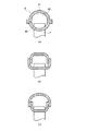
内部に冷媒が流通する流通路(124)が形成されるタンク部(121)と、前記チューブ(110)の端部(111)が挿入されるチューブ挿入孔(122a)を有するプレート部(122)とで構成され、
前記タンク部(121)の前記チューブ挿入孔(122a)と対向しない部分に、前記プレート部(122)と接触して前記タンク部(121)の流通路(124)を2つ以上に仕切る仕切部(126)を設け、前記タンク部(121)の前記チューブ挿入孔(122a)と対向する部分に、前記タンク部(121)の2つ以上の流通路(124)と連通する連通部(125)を設けたことを特徴とする熱交換器のヘッダタンク。 - 前記タンク部(121)の幅(a)、板厚(t)、及びチューブの幅(b)の関係が、
a−2t<b<a
であり、前記タンク部(121)の端部断面(121a)に前記チューブ(110)の端部(111)を当接させることで前記チューブ(110)の端部(111)を位置決めすることを特徴とする請求項1に記載の熱交換器のヘッダタンク。 - 前記タンク部(121)が前記チューブ挿入孔(122a)と対向する部分において、前記タンク部(121)の端部断面(121a)が前記プレート部(122)の主面(122b)と当接しないことを特徴とする請求項1又は2に記載の熱交換器のヘッダタンク。
- 少なくとも、前記タンク部(121)と前記プレート部(122)との嵌合部分(122b)において、前記タンク部(121)の端部断面(121a)が前記プレート部(122)の主面(122d)と当接することを特徴とする請求項1乃至3のいずれか一項に記載の熱交換器のヘッダタンク。
- 前記タンク部(121)の少なくとも流通路(124)側の表面にはロウ材層が存在せず、前記プレート部(122)の両面にはロウ材層が存在することを特徴とする請求項1乃至4のいずれか一項に記載の熱交換器のヘッダタンク。
- 前記タンク部(121)及び前記プレート部(122)が、それぞれプレス加工により成型されたものであることを特徴とする請求項1乃至5のいずれか一項に記載の熱交換器のヘッダタンク。
- 前記タンク部(121)に設けられた前記連通部(125)は、プレス加工により成型されたものであることを特徴とする請求項1乃至6のいずれか一項に記載の熱交換器のヘッダタンク。
- 前記プレート部(122)は、両端の側壁部(122c)が外側に向かって傾斜していることを特徴とする請求項1乃至7のいずれか一項に記載の熱交換器のヘッダタンク。
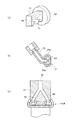
- 請求項1に記載の熱交換器のヘッダタンクと冷媒流通配管との接続構造であって、
前記冷媒流通配管(150、160)は、直線配管(151、161)と、この直線配管の内部と連通するように接合された屈曲配管(152、162)とで構成され、
冷媒入口側では前記タンク部(121)の2つ以上の流通路(124)のうちの一つに第1直線配管(151)が接続し、他の少なくとも1つの流通路には前記第1直線配管(151)から分岐した第1屈曲配管(152)が接続するとともに、
冷媒出口側では前記冷媒入口側において前記第1直線配管(151)が接続した流通路とは別の流通路に第2直線配管(161)が接続し、他の少なくとも一つの流通路に前記第2直線配管(161)から分岐した第2屈曲配管(162)が接続することを特徴とする熱交換器のヘッダタンクと冷媒流通配管との接続構造。 - 前記冷媒流通配管(150、160)は、前記直線配管(151、161)の側壁部に形成された開口孔と、前記屈曲配管(152、162)の開口端を接合した構造であることを特徴とする請求項9に記載の熱交換器のヘッダタンクと冷媒流通配管との接続構造。
- 前記冷媒流通配管(150、160)は、前記直線配管(151、161)の側壁部に形成された開口孔と、前記屈曲配管(152、162)の開口端との間を、接続部材(170)を介して接合した構造であることを特徴とする請求項9に記載の熱交換器のヘッダタンクと冷媒流通配管との接続構造。
- 前記冷媒流通配管(150)は、前記直線配管(151)の側壁部に形成された開口孔と、前記屈曲配管(152)の開口端との間を、冷媒流入側の下端部(180a)が前記直線配管(151)の内部に突出するように形成された接続部材(180)を介して接合した構造であることを特徴とする請求項9に記載の熱交換器のヘッダタンクと冷媒流通配管との接続構造。
Priority Applications (1)
| Application Number | Priority Date | Filing Date | Title |
|---|---|---|---|
| JP2004244088A JP4533040B2 (ja) | 2004-08-24 | 2004-08-24 | 熱交換器のヘッダタンクと冷媒流通配管との接続構造 |
Applications Claiming Priority (1)
| Application Number | Priority Date | Filing Date | Title |
|---|---|---|---|
| JP2004244088A JP4533040B2 (ja) | 2004-08-24 | 2004-08-24 | 熱交換器のヘッダタンクと冷媒流通配管との接続構造 |
Publications (2)
| Publication Number | Publication Date |
|---|---|
| JP2006064201A true JP2006064201A (ja) | 2006-03-09 |
| JP4533040B2 JP4533040B2 (ja) | 2010-08-25 |
Family
ID=36110845
Family Applications (1)
| Application Number | Title | Priority Date | Filing Date |
|---|---|---|---|
| JP2004244088A Expired - Fee Related JP4533040B2 (ja) | 2004-08-24 | 2004-08-24 | 熱交換器のヘッダタンクと冷媒流通配管との接続構造 |
Country Status (1)
| Country | Link |
|---|---|
| JP (1) | JP4533040B2 (ja) |
Cited By (5)
| Publication number | Priority date | Publication date | Assignee | Title |
|---|---|---|---|---|
| WO2007028542A1 (de) * | 2005-09-08 | 2007-03-15 | Behr Gmbh & Co. Kg | Wärmeübertrager, insbesondere gaskühler |
| JP2008080345A (ja) * | 2006-09-26 | 2008-04-10 | Calsonic Kansei Corp | 熱交換器用ヘッダタンクのタンク製造方法 |
| EP2006631A1 (fr) * | 2007-06-22 | 2008-12-24 | Valeo Systèmes Thermiques | Bride de collecteur pour un échangeur de chaleur |
| WO2021005682A1 (ja) * | 2019-07-08 | 2021-01-14 | 三菱電機株式会社 | 冷媒分配器、熱交換器、熱交換器ユニット、及び冷凍サイクル装置 |
| WO2026063223A1 (ja) * | 2024-09-19 | 2026-03-26 | 株式会社ティラド | 熱交換器 |
Families Citing this family (1)
| Publication number | Priority date | Publication date | Assignee | Title |
|---|---|---|---|---|
| KR101786965B1 (ko) * | 2010-10-28 | 2017-11-15 | 삼성전자주식회사 | 헤더유닛 및 이를 가지는 열교환기 |
Citations (4)
| Publication number | Priority date | Publication date | Assignee | Title |
|---|---|---|---|---|
| JPH11226685A (ja) * | 1998-02-16 | 1999-08-24 | Denso Corp | 熱交換器およびヘッダタンクの製造方法 |
| JPH11325784A (ja) * | 1998-03-16 | 1999-11-26 | Denso Corp | 熱交換器 |
| JP2003156296A (ja) * | 2001-11-19 | 2003-05-30 | Denso Corp | 熱交換器 |
| JP2004184001A (ja) * | 2002-12-04 | 2004-07-02 | Japan Climate Systems Corp | 熱交換器 |
-
2004
- 2004-08-24 JP JP2004244088A patent/JP4533040B2/ja not_active Expired - Fee Related
Patent Citations (4)
| Publication number | Priority date | Publication date | Assignee | Title |
|---|---|---|---|---|
| JPH11226685A (ja) * | 1998-02-16 | 1999-08-24 | Denso Corp | 熱交換器およびヘッダタンクの製造方法 |
| JPH11325784A (ja) * | 1998-03-16 | 1999-11-26 | Denso Corp | 熱交換器 |
| JP2003156296A (ja) * | 2001-11-19 | 2003-05-30 | Denso Corp | 熱交換器 |
| JP2004184001A (ja) * | 2002-12-04 | 2004-07-02 | Japan Climate Systems Corp | 熱交換器 |
Cited By (6)
| Publication number | Priority date | Publication date | Assignee | Title |
|---|---|---|---|---|
| WO2007028542A1 (de) * | 2005-09-08 | 2007-03-15 | Behr Gmbh & Co. Kg | Wärmeübertrager, insbesondere gaskühler |
| JP2008080345A (ja) * | 2006-09-26 | 2008-04-10 | Calsonic Kansei Corp | 熱交換器用ヘッダタンクのタンク製造方法 |
| EP2006631A1 (fr) * | 2007-06-22 | 2008-12-24 | Valeo Systèmes Thermiques | Bride de collecteur pour un échangeur de chaleur |
| WO2021005682A1 (ja) * | 2019-07-08 | 2021-01-14 | 三菱電機株式会社 | 冷媒分配器、熱交換器、熱交換器ユニット、及び冷凍サイクル装置 |
| JPWO2021005682A1 (ja) * | 2019-07-08 | 2021-01-14 | ||
| WO2026063223A1 (ja) * | 2024-09-19 | 2026-03-26 | 株式会社ティラド | 熱交換器 |
Also Published As
| Publication number | Publication date |
|---|---|
| JP4533040B2 (ja) | 2010-08-25 |
Similar Documents
| Publication | Publication Date | Title |
|---|---|---|
| US7044208B2 (en) | Heat exchanger | |
| US6176303B1 (en) | Heat exchanger and method for manufacturing header tank | |
| JP4724433B2 (ja) | 熱交換器 | |
| JP2005326135A (ja) | 熱交換器 | |
| JP2007298197A (ja) | 熱交換器 | |
| WO2007132779A1 (ja) | 熱交換器の配管コネクタ | |
| US20040211551A1 (en) | Heat exchanger, heat exchanger header tank and manufacturing method thereof | |
| WO2014041771A1 (ja) | 熱交換器 | |
| JP2011064379A (ja) | 熱交換器 | |
| JP4533726B2 (ja) | エバポレータおよびその製造方法 | |
| JP4774238B2 (ja) | 冷凍サイクルの冷媒流通部接続構造 | |
| JP2007093025A (ja) | 熱交換器およびその製造方法 | |
| JP2007147172A (ja) | 熱交換器 | |
| JP4533040B2 (ja) | 熱交換器のヘッダタンクと冷媒流通配管との接続構造 | |
| JPWO2004081481A1 (ja) | 熱交換器用タンクとコネクタとの接続構造 | |
| JP2016176686A (ja) | タンク、および熱交換器 | |
| JP2008249241A (ja) | 熱交換器 | |
| JP2009008347A (ja) | 熱交換器 | |
| JP2009287907A (ja) | 熱交換器 | |
| JP2007147173A (ja) | 熱交換器およびその製造方法 | |
| JP4759297B2 (ja) | 熱交換器 | |
| JP2008281270A (ja) | 熱交換器 | |
| JP2010121794A (ja) | 熱交換器 | |
| JP5525805B2 (ja) | 熱交換器 | |
| JP2006029765A (ja) | 熱交換器 |
Legal Events
| Date | Code | Title | Description |
|---|---|---|---|
| A621 | Written request for application examination |
Free format text: JAPANESE INTERMEDIATE CODE: A621 Effective date: 20070424 |
|
| A131 | Notification of reasons for refusal |
Free format text: JAPANESE INTERMEDIATE CODE: A131 Effective date: 20091124 |
|
| A521 | Written amendment |
Free format text: JAPANESE INTERMEDIATE CODE: A523 Effective date: 20100122 |
|
| TRDD | Decision of grant or rejection written | ||
| A01 | Written decision to grant a patent or to grant a registration (utility model) |
Free format text: JAPANESE INTERMEDIATE CODE: A01 Effective date: 20100608 |
|
| A01 | Written decision to grant a patent or to grant a registration (utility model) |
Free format text: JAPANESE INTERMEDIATE CODE: A01 |
|
| A61 | First payment of annual fees (during grant procedure) |
Free format text: JAPANESE INTERMEDIATE CODE: A61 Effective date: 20100611 |
|
| R150 | Certificate of patent (=grant) or registration of utility model |
Free format text: JAPANESE INTERMEDIATE CODE: R150 |
|
| FPAY | Renewal fee payment (prs date is renewal date of database) |
Free format text: PAYMENT UNTIL: 20130618 Year of fee payment: 3 |
|
| R250 | Receipt of annual fees |
Free format text: JAPANESE INTERMEDIATE CODE: R250 |
|
| LAPS | Cancellation because of no payment of annual fees |