JP2006094792A - Greening system for rooftop or the like - Google Patents
Greening system for rooftop or the like Download PDFInfo
- Publication number
- JP2006094792A JP2006094792A JP2004285880A JP2004285880A JP2006094792A JP 2006094792 A JP2006094792 A JP 2006094792A JP 2004285880 A JP2004285880 A JP 2004285880A JP 2004285880 A JP2004285880 A JP 2004285880A JP 2006094792 A JP2006094792 A JP 2006094792A
- Authority
- JP
- Japan
- Prior art keywords
- walking
- planting
- unit
- water
- water storage
- Prior art date
- Legal status (The legal status is an assumption and is not a legal conclusion. Google has not performed a legal analysis and makes no representation as to the accuracy of the status listed.)
- Pending
Links
- XLYOFNOQVPJJNP-UHFFFAOYSA-N water Substances O XLYOFNOQVPJJNP-UHFFFAOYSA-N 0.000 claims abstract description 77
- 230000035699 permeability Effects 0.000 description 3
- 239000008400 supply water Substances 0.000 description 3
- 238000010276 construction Methods 0.000 description 2
- 238000012423 maintenance Methods 0.000 description 2
- 239000000463 material Substances 0.000 description 2
- 239000004745 nonwoven fabric Substances 0.000 description 2
- 239000002689 soil Substances 0.000 description 2
- 238000004891 communication Methods 0.000 description 1
- 230000008595 infiltration Effects 0.000 description 1
- 238000001764 infiltration Methods 0.000 description 1
- 238000009434 installation Methods 0.000 description 1
- 238000012986 modification Methods 0.000 description 1
- 230000004048 modification Effects 0.000 description 1
- 230000035515 penetration Effects 0.000 description 1
Images

Classifications
-
- Y—GENERAL TAGGING OF NEW TECHNOLOGICAL DEVELOPMENTS; GENERAL TAGGING OF CROSS-SECTIONAL TECHNOLOGIES SPANNING OVER SEVERAL SECTIONS OF THE IPC; TECHNICAL SUBJECTS COVERED BY FORMER USPC CROSS-REFERENCE ART COLLECTIONS [XRACs] AND DIGESTS
- Y02—TECHNOLOGIES OR APPLICATIONS FOR MITIGATION OR ADAPTATION AGAINST CLIMATE CHANGE
- Y02A—TECHNOLOGIES FOR ADAPTATION TO CLIMATE CHANGE
- Y02A30/00—Adapting or protecting infrastructure or their operation
- Y02A30/24—Structural elements or technologies for improving thermal insulation
- Y02A30/254—Roof garden systems; Roof coverings with high solar reflectance
-
- Y—GENERAL TAGGING OF NEW TECHNOLOGICAL DEVELOPMENTS; GENERAL TAGGING OF CROSS-SECTIONAL TECHNOLOGIES SPANNING OVER SEVERAL SECTIONS OF THE IPC; TECHNICAL SUBJECTS COVERED BY FORMER USPC CROSS-REFERENCE ART COLLECTIONS [XRACs] AND DIGESTS
- Y02—TECHNOLOGIES OR APPLICATIONS FOR MITIGATION OR ADAPTATION AGAINST CLIMATE CHANGE
- Y02B—CLIMATE CHANGE MITIGATION TECHNOLOGIES RELATED TO BUILDINGS, e.g. HOUSING, HOUSE APPLIANCES OR RELATED END-USER APPLICATIONS
- Y02B80/00—Architectural or constructional elements improving the thermal performance of buildings
- Y02B80/32—Roof garden systems
Landscapes
- Cultivation Of Plants (AREA)
Abstract
Description
本発明は、建物の屋上などに形成する緑化システムに関する。 The present invention relates to a greening system formed on the roof of a building.
例えば建物の屋上に形成される緑化システムとして、従来より様々なものが提供されているが、屋上床面は自然の土でつくられてはいないので、雨による直接給水だけでは、植物にとって水不足になる場合があり、そのため、植栽部の下部に貯水タンクを備えさせて貯水したり、貯水タンクを植栽部に併設し、それらタンクから植物に給水されるようにしたものが提供されている。
しかしながら、植栽部の下部に貯水部を設けて貯水する構造では、貯水部を含む植栽部の高さ寸法が大きくなってしまうという問題がある。 However, in a structure in which a water storage part is provided at the lower part of the planting part to store water, there is a problem that the height dimension of the planting part including the water storage part becomes large.
また、雨水集水タンクを植栽部に併設した構造では、タンクを設置するスペースが必要となり、タンク設置部分がデッドスペースになってしまうという問題がある。 Moreover, in the structure where the rainwater collection tank is provided in the planting part, a space for installing the tank is required, and there is a problem that the tank installation part becomes a dead space.
本発明は、上記のような従来の問題点に鑑み、屋上等に設けられる緑化システムにおいて、植物への給水性能に優れ、しかも、植栽部の高さ寸法を小さく抑えることができ、デッドスペースを生じさせることもない緑化システムを提供することを課題とする。 In view of the conventional problems as described above, the present invention is excellent in water supply performance to plants in a tree planting system provided on a rooftop or the like, and can suppress the height dimension of a planting part to a small size. It is an object to provide a greening system that does not cause any problems.
上記の課題は、平板状の植栽ユニットと、同じく平板状の歩行ユニットとが敷き並べられて構成され、
平板状歩行ユニットは、透水性の歩行面の下部に、歩行面を通じて流れ落ちる水を貯める貯水タンク部を備えたものからなり、
該平板状歩行ユニットの貯水タンク部から平板状植栽ユニットに給水されるようになされていることを特徴とする屋上等の緑化システムによって解決される。
The above-mentioned problem is configured by arranging a flat planting unit and a flat walking unit,
The flat walking unit consists of a water storage tank that stores water flowing down through the walking surface at the bottom of the permeable walking surface.
This is solved by a greening system such as a rooftop characterized in that water is supplied from the water storage tank portion of the flat walking unit to the flat planting unit.
この緑化システムでは、植栽ユニットが、雨水等を受けて給水されるだけでなく、歩行ユニットが雨水等を受けてその下部の貯水ダンク部に貯水され、その水が植栽ユニットに給水されるようになされているので、植栽ユニットの植物に対する給水性能に優れる。 In this tree planting system, not only the planting unit receives rainwater, but also supplies water, the walking unit receives rainwater, etc., and stores it in the storage dunk part below it, and the water is supplied to the planting unit. Since it is made so, it is excellent in the water supply performance with respect to the plant of a planting unit.
しかも、植栽ユニットと歩行ユニットとを組み合わせて、貯水タンク部を歩行ユニットに備えさせたものであるから、植栽ユニットの高さ寸法を小さく抑えることができる。また、歩行ユニットについても、植栽ユニットとは異なり、そもそも高さ寸法を小さく設定できる歩行ユニットに対して、貯水タンク部を備えさせているので、貯水タンク部を含む歩行ユニットの高さ寸法を小さく抑えることができる。こうして、全体として薄型の緑化システムを実現することができる。 Moreover, since the planting unit and the walking unit are combined and the water storage tank portion is provided in the walking unit, the height dimension of the planting unit can be kept small. Also, unlike the planting unit, the walking unit is equipped with a water storage tank for the walking unit that can be set to a small height, so the height of the walking unit including the water storage tank It can be kept small. Thus, an overall thin greening system can be realized.
加えて、貯水タンク部は歩行ユニットの歩行面の下部に備えられていて、貯水タンク部の上部は歩行面に構成されているので、貯水タンク部によってデッドスペースを生じることもなく、植栽ユニットと歩行ユニットとの組み合わせによっては、植栽ユニットへの接近が容易な使い勝手の良い緑化を実現することも可能になる。 In addition, the water storage tank part is provided in the lower part of the walking surface of the walking unit, and the upper part of the water storage tank part is configured in the walking surface, so that no dead space is generated by the water storage tank part, and the planting unit Depending on the combination of the walking unit and the walking unit, it is possible to realize easy-to-use greening that allows easy access to the planting unit.
更に、平板状の植栽ユニットと、平板状の歩行ユニットとを敷き並べて構成される緑化システムであるので、施工やメンテナンス、撤去等をユニット単位で行うことができて取扱いが容易であり、ユニットを単位とする組み合わせによって様々な緑化デザインを実現することができる。 Furthermore, since it is a tree planting system constructed by arranging flat planting units and flat walking units, construction, maintenance, removal, etc. can be performed on a unit basis, and handling is easy. Various greening designs can be realized by the combination of the units.
また、上記の課題は、植栽部と歩行部とで構成され、
歩行部は、透水性の歩行面の下部に、歩行面を通じて流れ落ちる水を貯める貯水タンク部を備えたものからなり、
該歩行部の貯水タンク部から植栽部に給水されるようになされていることを特徴とする屋上等の緑化システムによっても解決される。
Moreover, said subject consists of a planting part and a walk part,
The walking part consists of a water storage tank part that stores water that flows down through the walking surface at the bottom of the permeable walking surface.
The problem can also be solved by a greening system such as a rooftop characterized in that water is supplied to the planting part from the water storage tank part of the walking part.
即ち、本発明の緑化システムでは、植栽部と歩行部がそれぞれユニット式に構成されている場合のほか、いずれか一方又は両方がユニット式に構成されていない場合も含む。また、歩行部は背高な貯水タンク部を備えていてもよいし、植栽部と歩行部との間に段差はあってもなくてもよい。 That is, in the tree planting system of the present invention, in addition to the case where the planting part and the walking part are each configured as a unit type, the case where either one or both are not configured as a unit type is included. Moreover, the walking part may be provided with a tall water storage tank part, and there may or may not be a step between the planting part and the walking part.
本発明の緑化システムは、以上のとおりのものであるから、屋上等に設けられるものでありながら、植物への給水性能に優れ、しかも、植栽部の高さ寸法を小さく抑えることができ、デッドスペースを生じさせることもなく、また、緑化部分と歩行部分との組み合わせ方によっては、使い勝手の良い緑化システムを構築することも可能になる。 Since the greening system of the present invention is as described above, it is excellent in water supply performance to plants, while being provided on the rooftop, etc., and can further suppress the height dimension of the planting part, A dead space is not generated, and an easy-to-use greening system can be constructed depending on how the greening portion and the walking portion are combined.
次に、本発明の実施最良形態を図面に基づいて説明する。 Next, the best mode for carrying out the present invention will be described with reference to the drawings.
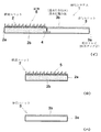
図1(イ)に示す実施形態の緑化システム1において、2は植栽ユニット、3は歩行ユニットである。植栽ユニット2は、図1(ロ)に示すように、正方形状のトレイ2aに土壌、不織布等の培地材2bが入れられた平板状のもので、培地材2bに植物5が植えられている。なお、植栽トレイ2aの底板部が、排水と保水のための形状部分を備えているのはいうまでもない。
In the
一方、歩行ユニット3は、図1(ハ)に示すように、貯水タンク部を構成する正方形状のトレイ3aの上部に、透水性を有する踏み板3bを付けた平板状のもので、踏み板3bそれ自体の透水性によって雨水等が下の貯水トレイ3a内に貯水されるようになされている。
On the other hand, as shown in FIG. 1 (C), the
そして、上記の植栽ユニット2と歩行ユニット3とは、同じ平面サイズに設定されていて、屋上などの床面において、図1(イ)に示すように、辺と辺を合わせるようにして隣り合わせ状態に敷き並べられ、歩行ユニット3の貯水トレイ3a内と植栽ユニット2の植栽トレイ2a内がパイプ4で連通されて、緑化システムを構成している。
The
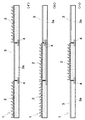
植栽ユニット2と歩行ユニット3とは、図1(イ)に示すように、一つの歩行ユニット3の貯水トレイ3aから一つの植栽ユニット2に給水されるように組み合わせてもよいが、図2(イ)に示すように、複数の植栽ユニット2,2を一つの歩行ユニット3の複数辺に隣り合わせて一つの歩行ユニット3の貯水トレイ3aから複数の植栽ユニット2,2に給水されるようにしてもよい。また、図2(ロ)に示すように、植栽ユニット2を挟む一方の側に歩行ユニット3を組み合わせ、もう一方の側に植栽ユニット2を組み合わせ、前記一方の歩行ユニット3の貯水トレイ3aから、パイプ4,4で、複数の植栽ユニット2,2に給水されるようにしてもよい。また、図2(ハ)に示すように、複数の歩行ユニット3,3を一つの植栽ユニット2の複数辺に隣り合わせて複数の歩行ユニット3,3の貯水トレイ3a,3aから一つの植栽ユニット2に給水されるようにしてもよい。
The
また、一つの歩行ユニット3の貯水トレイ3aから一つの植栽ユニット2に給水する組み合わせにおいて、図3(イ)に示すように、隣り合わせた複数の植栽ユニット2,2を挟む両側に歩行ユニット3,3を隣り合わせて、広幅の植栽部の両側に歩行部を形成するのもよいし、また、図3(ロ)に示すように、隣り合わせた複数の歩行ユニット3,3の両側に植栽ユニット2,2を隣り合わせて、両側から植栽部で挟まれた広幅の歩行部を形成するのもよい。
Moreover, in the combination which supplies water to the one
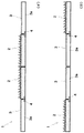
また、同じく一つの歩行ユニット3から一つの植栽ユニット2に給水する組み合わせにおいて、図4(イ)に示すように、植栽ユニット2…の列と歩行ユニット3…の列とを交互配置で隣り合わせたり、図4(ロ)に示すように、複数の植栽ユニット2…と複数の歩行ユニット3…とで市松模様状配置となるように隣り合わせるのもよい。また、一つの歩行ユニット3から一つの植栽ユニット2に給水する組み合わせと、一つの歩行ユニット3から複数の植栽ユニット2に給水する組み合わせとを組み合わせ、図4(ハ)に示すように、植栽ユニット2…を複数列組み合わせてその両側に歩行ユニット3…の列を組み合わせ、一方の歩行ユニット3…を挟む更にもう一方の側に植栽ユニット2…の列を隣り合わせるようにするのもよい。
Similarly, in the combination of supplying water from one
また、図4(ニ)に示すように、歩行ユニット3を複数の植栽ユニット2…からなる植栽部内に点在させ、一つの歩行ユニット3の貯水トレイ3aから周囲4つの植栽ユニット2…に給水する配置にするのもよい。
Further, as shown in FIG. 4 (d), the
上記の緑化システムでは、雨が降ると、植栽ユニット2が、雨水を受けて給水されるだけでなく、歩行ユニット3も雨水を受けてその下部の貯水トレイ3a内に貯水され、その水がパイプ4を通じて植栽ユニット2のトレイ2a内に給水され、雨量が少ないときでも、植栽ユニット2の植物5に充分な量の水を供給することができ、高い給水性能を発揮することができる。ホースで散水する場合も同様である。
In the above-mentioned greening system, when it rains, the
そして、植栽ユニット2と歩行ユニット3とを組み合わせて、歩行ユニット3に貯水トレイ3aを備えさせたものであるから、植栽ユニット2の高さ寸法を小さく抑えることができ、歩行ユニット3についても、植栽ユニット2とは異なり、そもそも高さ寸法を小さく設定できる歩行ユニットに対して、貯水トレイ3aを備えさせているので、貯水トレイ3aと踏み板3bとを含む全体の高さ寸法を小さく抑えることができ、こうして、全体として薄型の緑化システム1を実現することができる。
And since the
しかも、貯水タンク部は、歩行ユニット3の踏み板3bの下部の貯水トレイ3aで構成されていて、貯水トレイ3aの上部に踏み板3bが備えられているので、貯水タンク部を備えさせることによってデッドスペースを生じてしまうこともなく、逆に、図1(イ)や図2〜図4に示すように、歩行ユニット3によって植栽ユニット2への接近が容易な使い勝手の良い緑化を実現することが可能である。
In addition, the water storage tank portion is composed of a
また、平板状の植栽ユニット2と、平板状の歩行ユニット3とを敷き並べて構成される緑化システム1であるので、施工やメンテナンス、撤去等をユニット単位で行うことができて取扱いが容易であり、ユニットを単位とする組み合わせによって上記のような様々な緑化デザインを実現することができる。
Moreover, since it is the
以上に、本発明の実施形態を示したが、本発明はこれに限られるものではなく、発明思想を逸脱しない範囲で各種の変更が可能である。例えば、上記の実施形態では、植栽ユニット2と歩行ユニット3とが、同じ平面サイズの平面視正方形状をしている場合を示したが、同じ平面サイズの平面視正六角形状をして蜂の巣状配置に組み合わされてもよいし、また、同じ平面サイズの平面視円形状をして隣り合わせ状態に配置されてもよいし、また、植栽ユニットと歩行ユニットとを互いに異なる平面サイズにしてもよいし、植栽ユニットとして平面サイズや平面形状の異なる複数種類のものが用いられてもよいし、歩行ユニットとして平面サイズや平面形状の異なる複数種類のものが用いられてもよく、植栽ユニット、歩行ユニットの平面形状、平面サイズに制限はない。
Although the embodiment of the present invention has been described above, the present invention is not limited to this, and various modifications can be made without departing from the spirit of the invention. For example, in the above embodiment, the case where the
また、上記の実施形態では、歩行ユニット3の透水性の歩行面を、それ自体で透水性を備えた踏み板3bを用いて構成した場合を示したが、踏み板3bそれ自体に透水性が備えられている必要はなく、要は、雨水等が踏み板を越えて下の貯水トレー内に貯水されるように構成されていればよい。
In the above embodiment, the case where the water-permeable walking surface of the
更に、上記の実施形態では、貯水トレイ3aと植栽ユニット2とをパイプ4で連通させて給水されるようにした場合を示したが、貯水トレイ3aと植栽ユニット2とに不織布等の浸透性部材を渡して給水するようにしてもよい。
Furthermore, in said embodiment, although the case where the
また、本発明の緑化システムは、建物の屋上の床面のほか、バルコニーの床面や、庭など、植物をじか植えできないような、緑化分野において言われる、いわゆる人工地盤上に設置して用いることができるものであることはいうまでもない。 Moreover, the greening system of the present invention is installed on the so-called artificial ground, which is said in the field of greening, where the plant cannot be planted directly, such as the floor surface of the building, the floor surface of the balcony, or the garden. Needless to say, it can be used.
1…緑化システム
2…植栽ユニット
3…歩行ユニット
3a…貯水トレイ
3b…踏み板(透水性の歩行面)
5…植物
DESCRIPTION OF
5 ... Plants
Claims (2)
平板状歩行ユニットは、透水性の歩行面の下部に、歩行面を通じて流れ落ちる水を貯める貯水タンク部を備えたものからなり、
該平板状歩行ユニットの貯水タンク部から平板状植栽ユニットに給水されるようになされていることを特徴とする屋上等の緑化システム。 A flat planting unit and a flat walking unit are also laid and arranged,
The flat walking unit consists of a water storage tank that stores water flowing down through the walking surface at the bottom of the permeable walking surface.
A greening system for a rooftop or the like, wherein water is supplied from the water storage tank portion of the flat walking unit to the flat planting unit.
歩行部は、透水性の歩行面の下部に、歩行面を通じて流れ落ちる水を貯める貯水タンク部を備えたものからなり、
該歩行部の貯水タンク部から植栽部に給水されるようになされていることを特徴とする屋上等の緑化システム。 It consists of a planting part and a walking part,
The walking part consists of a water storage tank part that stores water that flows down through the walking surface at the bottom of the permeable walking surface.
A greening system for a rooftop or the like, wherein water is supplied to a planting part from a water storage tank part of the walking part.
Priority Applications (1)
| Application Number | Priority Date | Filing Date | Title |
|---|---|---|---|
| JP2004285880A JP2006094792A (en) | 2004-09-30 | 2004-09-30 | Greening system for rooftop or the like |
Applications Claiming Priority (1)
| Application Number | Priority Date | Filing Date | Title |
|---|---|---|---|
| JP2004285880A JP2006094792A (en) | 2004-09-30 | 2004-09-30 | Greening system for rooftop or the like |
Publications (1)
| Publication Number | Publication Date |
|---|---|
| JP2006094792A true JP2006094792A (en) | 2006-04-13 |
Family
ID=36235195
Family Applications (1)
| Application Number | Title | Priority Date | Filing Date |
|---|---|---|---|
| JP2004285880A Pending JP2006094792A (en) | 2004-09-30 | 2004-09-30 | Greening system for rooftop or the like |
Country Status (1)
| Country | Link |
|---|---|
| JP (1) | JP2006094792A (en) |
Cited By (2)
| Publication number | Priority date | Publication date | Assignee | Title |
|---|---|---|---|---|
| JP2007330103A (en) * | 2006-06-12 | 2007-12-27 | Tajima Roofing Co Ltd | Planting device, and foothold for maintenance of planting device |
| CN105009893A (en) * | 2015-07-09 | 2015-11-04 | 陈小昌 | Wild rice shoot and freshwater crayfish joint ecological culture method |
Citations (1)
| Publication number | Priority date | Publication date | Assignee | Title |
|---|---|---|---|---|
| JP2004201603A (en) * | 2002-12-26 | 2004-07-22 | Kyodo Ky Tec Corp | Temperature rise-preventing structure |
-
2004
- 2004-09-30 JP JP2004285880A patent/JP2006094792A/en active Pending
Patent Citations (1)
| Publication number | Priority date | Publication date | Assignee | Title |
|---|---|---|---|---|
| JP2004201603A (en) * | 2002-12-26 | 2004-07-22 | Kyodo Ky Tec Corp | Temperature rise-preventing structure |
Cited By (2)
| Publication number | Priority date | Publication date | Assignee | Title |
|---|---|---|---|---|
| JP2007330103A (en) * | 2006-06-12 | 2007-12-27 | Tajima Roofing Co Ltd | Planting device, and foothold for maintenance of planting device |
| CN105009893A (en) * | 2015-07-09 | 2015-11-04 | 陈小昌 | Wild rice shoot and freshwater crayfish joint ecological culture method |
Similar Documents
| Publication | Publication Date | Title |
|---|---|---|
| US7392616B1 (en) | Modular field planting system | |
| KR101963203B1 (en) | A plant tray | |
| JP5142498B2 (en) | Planting equipment and planting structure for plants | |
| US20110225883A1 (en) | Vegetation wall | |
| JP2009513132A (en) | Container used for rooftop greening system and rooftop greening system using the container | |
| JP2010220591A (en) | Growing device with planting culture soil | |
| JPH0499411A (en) | Device of culturing plant | |
| JP2006129846A (en) | Planting block tray for wall greening equipment | |
| JP4976785B2 (en) | Roof greening system | |
| JP4657359B2 (en) | Greening system and tray for greening | |
| JP3581275B2 (en) | Planting equipment | |
| KR101187407B1 (en) | Wall-greening apparatus and wall-greening method using the same | |
| JP3847723B2 (en) | Tree planting equipment | |
| JP2003116356A (en) | Planting tray | |
| JP2006094792A (en) | Greening system for rooftop or the like | |
| JP4593459B2 (en) | Rooftop greening construction panel and rooftop greening construction system using the rooftop greening construction panel | |
| JP2004298146A (en) | Planting equipment and drain pan. | |
| JP4657683B2 (en) | Wall greening equipment | |
| JP2013090623A (en) | Building greening system | |
| JP2012010671A (en) | Greening panel and rooftop greening structure | |
| JP2009022245A (en) | Rooftop greening construction panel and rooftop greening construction system using the rooftop greening construction panel | |
| JP2008017850A (en) | Rooftop greening construction panel and rooftop greening construction system using the rooftop greening construction panel | |
| JP4747135B2 (en) | Planting mat and its laying method | |
| JP4906250B2 (en) | Tree planting infrastructure | |
| KR100624746B1 (en) | Structure of greening facility installed on the roof of apartment house |
Legal Events
| Date | Code | Title | Description |
|---|---|---|---|
| A621 | Written request for application examination |
Free format text: JAPANESE INTERMEDIATE CODE: A621 Effective date: 20070919 |
|
| A977 | Report on retrieval |
Free format text: JAPANESE INTERMEDIATE CODE: A971007 Effective date: 20091109 |
|
| A131 | Notification of reasons for refusal |
Free format text: JAPANESE INTERMEDIATE CODE: A131 Effective date: 20100713 |
|
| A521 | Written amendment |
Free format text: JAPANESE INTERMEDIATE CODE: A523 Effective date: 20100913 |
|
| A02 | Decision of refusal |
Free format text: JAPANESE INTERMEDIATE CODE: A02 Effective date: 20110222 |