JP2006100018A - Button device - Google Patents
Button device Download PDFInfo
- Publication number
- JP2006100018A JP2006100018A JP2004281870A JP2004281870A JP2006100018A JP 2006100018 A JP2006100018 A JP 2006100018A JP 2004281870 A JP2004281870 A JP 2004281870A JP 2004281870 A JP2004281870 A JP 2004281870A JP 2006100018 A JP2006100018 A JP 2006100018A
- Authority
- JP
- Japan
- Prior art keywords
- substrate
- button
- pressing
- inclined portion
- switch
- Prior art date
- Legal status (The legal status is an assumption and is not a legal conclusion. Google has not performed a legal analysis and makes no representation as to the accuracy of the status listed.)
- Granted
Links
Images




Landscapes
- Rotary Switch, Piano Key Switch, And Lever Switch (AREA)
Abstract
【課題】押圧スイッチの押圧方向に対して斜めに押圧操作されるボタンの嵌り込みを防止可能なボタン装置を提供する。
【解決手段】回路基板24と、回路基板24の面に垂直な方向を押圧方向として回路基板24に設けられる押圧スイッチ25と、押圧スイッチ25に対向する位置において回路基板24に対して傾斜し、孔部12cが設けられる傾斜部12aを有し、回路基板24に対して固定されるカバー12と、孔部12cに配置され、押圧操作により押圧スイッチ25を押圧するボタン22と、ボタン22に対して固定され、傾斜部12a側から回路基板24側へ突出し、回路基板24と傾斜部12aとが離間する側の当接面42aが、回路基板24の縁部24aに係合する突出部42と、を備える。
【選択図】図3
A button device capable of preventing a button that is pressed obliquely with respect to a pressing direction of a pressing switch from being fitted is provided.
A circuit board, a pressure switch provided on the circuit board with a direction perpendicular to the surface of the circuit board as a pressing direction, and a position facing the pressure switch are inclined with respect to the circuit board. A cover 12 having an inclined portion 12a provided with a hole 12c and fixed to the circuit board 24, a button 22 disposed in the hole 12c and pressing the pressing switch 25 by a pressing operation, and the button 22 The contact surface 42a on the side where the circuit board 24 and the inclined portion 12a are separated from each other is projected from the inclined portion 12a side to the circuit board 24 side, and the protruding portion 42 that engages with the edge portion 24a of the circuit board 24. .
[Selection] Figure 3
Description
本発明は、ボタン装置、より詳細には、押圧スイッチの押圧方向に対して斜めに押圧操作されるボタンを有するボタン装置に関するものである。 The present invention relates to a button device, and more particularly to a button device having a button that is pressed obliquely with respect to a pressing direction of a pressing switch.
デジタルカメラ等の機器において、筐体のデザインや装置の小型化等の理由から、押圧スイッチを押圧するためのボタンが、押圧スイッチの押圧方向に対して斜めに押圧操作されるように配置されることがある。このようなボタン装置として、キャビネットの基板に対して傾斜する部分に、押圧方向に揺動可能なボタンを設けるものが提案されている(特許文献4)。なお、押圧スイッチの押圧方向に対して斜めにボタンが押圧されるものではないが、ボタンと押圧スイッチとの間に、押圧方向へ揺動可能なアームを設け、当該アームに設けられた傾斜面により押圧スイッチを押圧するもの(特許文献3)、位置決め用の突部に取り付けられたアームによりボタンを揺動可能に支持するもの(特許文献1)、傾斜したケースに対応して、押圧スイッチが設けられる基板を傾斜させたもの(特許文献2)が提案されている。
図11(a)〜図11(c)は、従来のボタン装置500を示している。ボタン装置500は、回路基板501と、回路基板501上に設けられた押圧スイッチ502と、外装カバー503の一部であって、回路基板501に対して斜めに設けられた傾斜部503aと、傾斜部503aに設けられた孔部503bに配置されたボタン504とを備えている。
FIG. 11A to FIG. 11C show a
図11(a)に示すように、傾斜部503aに垂直な方向へボタン504が押圧操作されると、ボタン504により押圧スイッチ502の押圧面502aが押圧される。ボタン504に作用する力Fは、押圧面502aに垂直な分力Fxと、押圧面502aに沿う方向の分力Fyとを含んでいる。このため、図11(b)に示すように、分力Fyによりボタン504は押圧面502aに沿って平行移動又は回転移動する。この結果、ボタン504が孔部503bに対して斜めに嵌り込み、ボタン504の押圧操作前の位置への復帰が円滑にできなくなる。さらには、図11(c)に示すように、ボタン504が傾斜部503aと押圧面502aとの間に嵌り込み、押圧操作前の位置へ復帰できなくなる。
As shown in FIG. 11A, when the
なお、図11(a)〜(c)では、比較的広い押圧面502a上でボタン504が摺動する場合を例示したが、押圧スイッチ502の押圧方向とボタン504の操作方向とが互いに傾斜していれば、押圧面502aが比較的狭くても上記問題は生じ得る。
11A to 11C illustrate the case where the
本発明の目的は、押圧スイッチの押圧方向に対して斜めに押圧操作されるボタンの嵌り込みを防止可能なボタン装置を提供することにある。 An object of the present invention is to provide a button device capable of preventing a button that is pressed obliquely with respect to a pressing direction of a pressing switch.
本発明の第1の観点のボタン装置は、基板と、前記基板の面に垂直な方向を押圧方向として前記基板に設けられる押圧スイッチと、前記押圧スイッチに対向する位置において前記基板に対して傾斜し、孔部が設けられる傾斜部を有し、前記基板に対して固定されるカバーと、前記孔部に配置され、押圧操作により前記押圧スイッチを押圧するボタンと、前記ボタンに対して固定され、前記傾斜部側から前記基板側へ突出し、前記基板と前記傾斜部とが離間する側の縁部が、前記基板に対して固定された被係合部に係合する係合突出部と、を備える。 A button device according to a first aspect of the present invention includes a substrate, a press switch provided on the substrate with a direction perpendicular to the surface of the substrate as a pressing direction, and a tilt with respect to the substrate at a position facing the press switch. And a cover that has an inclined portion provided with a hole and is fixed to the substrate, a button that is disposed in the hole and presses the pressing switch by a pressing operation, and is fixed to the button. An engagement protrusion that protrudes from the inclined portion side to the substrate side, and an edge portion on a side where the substrate and the inclined portion are separated from each other is engaged with an engaged portion fixed to the substrate; Is provided.
好適には、前記被係合部は、前記基板の前記傾斜部と近接する側の縁部である。 Preferably, the engaged portion is an edge portion of the substrate on the side close to the inclined portion.
好適には、前記被係合部は、前記基板の前記傾斜部に対向する面から突出する被係合突出部である。 Preferably, the engaged portion is an engaged protrusion that protrudes from a surface of the substrate that faces the inclined portion.
好適には、前記被係合突出部は、前記押圧スイッチである。 Preferably, the engaged protrusion is the push switch.
好適には、前記基板と前記傾斜部とが近接する側から離間する側へ、前記傾斜部の前記基板に対向する面に沿って延び、前記近接する側の端部が前記カバーに固定され、前記離間する側の端部が前記ボタンに固定され、前記近接する側の端部を支点として前記ボタンを前記押圧方向に揺動可能に支持する支持部を備え、前記カバーは、前記基板の前記傾斜部と近接する側の縁部を前記傾斜部とで囲むように、前記傾斜部の前記基板と近接する側の縁部から前記基板の前記傾斜部に対向する面の背面側へ延びる延長部を有し、前記支持部は前記近接する側の端部が前記延長部に固定されている。 Preferably, the substrate and the inclined portion extend along a surface facing the substrate from a side where the substrate and the inclined portion are separated from each other, and an end portion on the adjacent side is fixed to the cover. An end portion on the side to be separated is fixed to the button, and a support portion that supports the button so as to be swingable in the pressing direction with the end portion on the close side as a fulcrum is provided. An extension portion extending from the edge portion of the inclined portion adjacent to the substrate to the back side of the surface facing the inclined portion of the substrate so as to surround the edge portion adjacent to the inclined portion with the inclined portion. The support portion has an end portion on the adjacent side fixed to the extension portion.
好適には、前記基板と前記傾斜部とが近接する側から離間する側へ、前記傾斜部の前記基板に対向する面に沿って延び、前記近接する側の端部が前記カバーに固定され、前記離間する側の端部が前記ボタンに固定され、前記近接する側の端部を支点として前記ボタンを前記押圧方向に揺動可能に支持する支持部を備え、前記係合突出部は、前記支持部から前記基板側へ突出している。 Preferably, the substrate and the inclined portion extend along a surface facing the substrate from a side where the substrate and the inclined portion are separated from each other, and an end portion on the adjacent side is fixed to the cover. An end portion on the side to be separated is fixed to the button, and a support portion that supports the button so as to be swingable in the pressing direction with the end portion on the close side as a fulcrum is provided. Projecting from the support portion toward the substrate.
好適には、前記ボタンは、前記傾斜部の前記基板と対向する面の背面側へ前記孔部を介して露出する操作部と、前記操作部から前記基板側へ突出し、前記操作部への押圧操作により前記押圧スイッチを押圧する押圧子とを備え、前記係合突出部は、前記押圧子に連続して設けられている。 Preferably, the button is exposed to the back side of the surface of the inclined portion facing the substrate through the hole, and protrudes from the operation portion to the substrate side, and is pressed to the operation portion. A pressing member that presses the pressing switch by an operation, and the engagement protrusion is provided continuously to the pressing member.
好適には、前記ボタンは、前記傾斜部の前記基板と対向する面の背面側へ前記孔部を介して露出する操作部と、前記操作部から前記基板側へ突出し、前記操作部への押圧操作により前記押圧スイッチを押圧する押圧子と、前記操作部から前記基板側へ突出し、前記操作部への押圧操作により前記基板の前記傾斜部と対向する面に当接する当接部と、を備える。 Preferably, the button is exposed to the back side of the surface of the inclined portion facing the substrate through the hole, and protrudes from the operation portion to the substrate side, and is pressed to the operation portion. A pressing member that presses the pressing switch by an operation; and a contact portion that protrudes from the operation portion toward the substrate side and contacts a surface of the substrate that faces the inclined portion by a pressing operation to the operation portion. .
本発明の第2の観点のボタン装置は、基板と、前記基板の面に垂直な方向を押圧方向として前記基板に設けられる押圧スイッチと、前記押圧スイッチに対向する位置において前記基板に対して傾斜し、孔部が設けられる傾斜部を有し、前記基板に対して固定されるカバーと、前記孔部に配置され、押圧操作により前記押圧スイッチを押圧するボタンと、前記カバーより前記基板側に設けられ、前記基板と前記傾斜部とが離間する側への前記基板の面に沿う前記ボタンの移動を規制する係止手段と、を備える。 A button device according to a second aspect of the present invention includes a substrate, a press switch provided on the substrate with a direction perpendicular to the surface of the substrate as a pressing direction, and a tilt with respect to the substrate at a position facing the press switch. And a cover that is fixed to the substrate and has an inclined portion provided with a hole, a button that is disposed in the hole and presses the pressing switch by a pressing operation, and closer to the substrate than the cover. And a locking means for restricting the movement of the button along the surface of the substrate toward the side where the substrate and the inclined portion are separated from each other.
本発明によれば、押圧スイッチの押圧方向に対して斜めに押圧操作されるボタンの嵌り込みを防止できる。 According to the present invention, it is possible to prevent the button that is pressed obliquely with respect to the pressing direction of the pressing switch from being fitted.
図1(a)及び図1(b)はそれぞれ、本発明のボタン装置が適用されたデジタルカメラ1を前面側から示す斜視図及び背面側から示す斜視図である。デジタルカメラ1は、筐体2、筐体2の前面側に露出する撮像ユニット3、筐体2の背面側に画像を表示する表示部4、筐体2の上面側に設けられ、シャッターの開閉操作のためのレリーズボタン5等のデジタルカメラを構成する各種の要素を備えている。
1A and 1B are a perspective view showing the
筐体2の背面側の上部には、ボタン装置21が設けられる。ボタン装置21は、筐体2の左右方向に配列された2個のボタン22を含み、2個のボタン22は、例えば、撮像した画像をデジタルカメラ1に接続されたプリンタから印刷するためのプリントボタン、撮像した画像に予め用意されたフレーム画像を重ねる操作を行うためのボタンとしてそれぞれ利用される。
A
なお、デジタルカメラ1は、基体13と、基体13に取り付けられ、筐体2の前面側及び背面側をそれぞれ構成する前面カバー11、背面カバー12とを備え、基体13と、前面カバー11及び背面カバー12との間には不図示の基板が内設される。
The
図2はボタン装置21の分解斜視図、図3は図1のIII−III線におけるボタン装置21の断面図である。ボタン装置21は、回路基板24に設けられる押圧スイッチ25と、押圧スイッチ25を押圧するためのボタン22を含むキートップ26とを備え、回路基板24の押圧スイッチ25側には背面カバー12が配置される。
2 is an exploded perspective view of the
回路基板24は、例えば多層式のプリント基板により構成される。回路基板24は、基体13(図2では不図示)の背面カバー12側に背面カバー12に対向するように配置され、ねじなどにより基体13に固定される。なお、回路基板24と背面カバー12とは、基体13を介して互いに固定されることになる。
The
押圧スイッチ25は、2個のボタン22に対応して2個設けられており、それぞれ回路基板24の上方(レリーズボタン側)の縁部24a近傍に縁部24aに沿って配列されている。押圧スイッチ25は、回路基板24側の固定接点(不図示)と、背面カバー12側の可動接点31とを備えている。可動接点31は、ドーム状の金属板であり、固定接点側を凹として固定接点に被せられる。可動接点31は、押圧スイッチ25の背面カバー12側の面に亘って広がっており、可動接点31上にフィルム状の保護膜(不図示)が被せられて押圧スイッチ25の押圧面25aが形成されている。可動接点31の中央が所定の変位まで回路基板24側に押圧されると、可動接点31は固定接点側が凸となるように凹凸を反転させ、固定接点に接触するとともに、クリック感を生じさせる。なお、押圧面25aをいずれの方向に押圧しても、可動接点31の凹凸を反転させてスイッチをオンとするのは、押圧面25aに対して垂直な方向の荷重によるものであることから、押圧スイッチ25の押圧方向は押圧面25a(回路基板24)に垂直な方向である。
Two
背面カバー12は、例えば金属により形成される。背面カバー12は、表示部4の配置位置が背面側に突出するように形成されており、表示部4を露出するために設けられた開口窓12dのレリーズボタン側(上方側)の縁部から、回路基板24側へ傾斜しつつレリーズボタン5側へ延びる傾斜部12aと、傾斜部12aのレリーズボタン5側の縁部から前面側に延びて、筐体2の上面を構成する上面部(延長部)12bとを有している。傾斜部12a、上面部12b等、背面カバー12の各部は略一様な厚さに形成されている。なお、上述のように、回路基板24は背面に対向するように配置されていることから、傾斜部12aは、基板24の面又は押圧面25aに対して傾斜し、上面部12bは、基板24の面又は押圧面25aに対して垂直である。傾斜部12aは、回路基板24の押圧スイッチ25が設けられる位置に対して対向して設けられており、傾斜部12aには、2個のボタン22を露出させるための2個の孔部12cがそれぞれ設けられている。孔部12cは、互いの配列方向に長い長孔に形成され、また、筐体外部側から筐体内部側へ向かって細くなるテーパ状に形成されている。背面カバー12はねじなどにより基体13に固定される。
The
図4はキートップ26を背面カバー12側から見た斜視図、図5はキートップ26の一部を回路基板24側から見た斜視図である。
4 is a perspective view of the key top 26 as seen from the
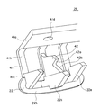
キートップ26は、例えば樹脂を一体成形して形成され、2個のボタン22と、2個のボタン22をそれぞれ支持する2個の支持部41と、係合突出部としての突出部42と、を備えている。ボタン22は、筐体2の表面に孔部12cを介して露出する操作部22aと、操作部22aの筐体外部側への移動を規制する抜け止め部22bと、操作部22aに対する押圧操作により押圧スイッチ25の押圧面25aを押圧する押圧子22cと、操作部22aに対する押圧操作により回路基板25に当接する当接部22eとを有している。
The key top 26 is formed, for example, by integrally molding a resin, and includes two
操作部22aは、ボタン22の配列方向に長い長円形に形成されており、所定の余裕(遊び)を有しつつ孔部12cに嵌合する。操作部22aの長手方向の長さは、押圧スイッチ25の幅よりも大きく設定され、筐体内部側から外部側への厚さは傾斜部12aの厚さよりも大きく設定されている(図3参照)。操作部22aの筐体内部側は凹状となっており、操作部22aの内部は中空となっている。なお、操作部22aは、孔部12cによって傾斜部12aに沿う方向の移動が規制されるから、傾斜部12aに対して垂直な方向に押圧操作されることになる。抜け止め部22bは、操作部22aの筐体内部側の外周から突出する鍔状に形成され、背面カバー12の孔部12cより幅広に設定されている。
The
押圧子22cは、操作部22aの長手方向の中央から筐体内部側に向かって突出し、操作部22aの長手方向に直交する板状に形成されている。操作部22aの長手方向における押圧子22cの厚さは、例えば操作部22aの長手方向の長さの10分の1程度である。押圧子22cは、操作部22aの長手方向と直交する方向において、操作部22aの幅と同程度の幅で操作部22aから突出し、当該幅を一定に保ちつつ筐体内部側へ延びた後、当該幅を徐々に狭くしつつ押圧スイッチ25へ向かって延びるように形成されており、比較的狭い面積で押圧面25aの中央部を押圧可能である(図3参照)。
The
当接部22eは、操作部22aの長手方向の両側からそれぞれ筐体内部側に突出し、押圧子22cに平行な板状に形成されている。当接部22eは、押圧子22cと比較して、やや支持部41側に配置されており、操作部22aから後述するアーム部41bに亘る範囲に裾野を有している。当接部22eは、筐体内部側に延びるに従い、操作部22aの長手方向と直交する方向における幅が徐々に狭くなるように形成され、また、操作部22aの長手方向における厚さが押圧子22cの厚さよりも若干薄く設定されている。当接部22eの操作部22aから筐体内部側への長さは、押圧子22cよりも押圧スイッチ25の厚さ分だけ、若しくは押圧スイッチ25の厚さより若干大きい分だけ、短く設定されており、図6に示すように、押圧子22aにより押圧スイッチ25が押圧され、可動接点31が反転すると、若しくは可動接点31の反転後さらに操作部22aが押圧されると、当接部22eは基板24の表面に当接する。
The
図4及び図5に示す支持部41は、背面カバー12に固定される固定部41aと、固定部41aから延びる3本のアーム部41bと、ボタン22に連続する接続部41cとを有している。固定部41aは、矩形の板状に形成されている。2個のボタン22にそれぞれ対応する2個の固定部41aは互いに連続するように形成され、一枚の板状に形成されている。2つの固定部41aは、操作部22aの長手方向中央に対応する位置に、背面カバー12の位置決め用突部12e(図3参照)へ嵌合する孔部41dがそれぞれ設けられている。また、2つの固定部41aの背面カバー12側の面には、2つの孔部41d間に、背面カバー12へ固定部41aを固定するための両面テープ43が配置される。固定部41aは、これら孔部41d、両面テープ43により、背面カバー12の上面部12bの筐体内部側へ固定される(図3参照)。
4 and 5 includes a fixing
アーム部41bは、操作部22aの長手方向の中央、両端にそれぞれ対応して3本設けられている。図3に示すように、アーム部41bは、固定部41aから上面部12bに沿って筐体2の背面側へ延びた後、上面部12bと傾斜部12aとの接続部付近で折れ曲がり、傾斜部12aに沿って延びている。そして、図4に示すように、3本のアーム部41bは操作部22aの長手方向に延びる接続部41cにそれぞれ連続し、接続部41cは抜け止め部22bに連続している。つまり、ボタン22は、支持部41の傾斜部12aに沿う部分に支持されており、固定部41dを支点とて傾斜部12aに垂直な方向に揺動可能である。なお、アーム部41bの幅は、操作部22aの長手方向における押圧子22cの厚さよりもやや大きい幅に設定されている。
Three
突出部42は、3本のアーム部41bのうち中央のアーム部41bから筐体内部側に向かって突出し、押圧子22cと同一平面に配置される板状に形成されている。また、突出部42の押圧子22c側の裾野は押圧子22cに連続する。ただし、突出部42の厚さ(操作部22aの長手方向)は、押圧子22cより若干薄く設定されている。突出部42は、図3にも示すように、押圧子22c側に、回路基板24に対して垂直に延びて回路基板24の縁部24aに当接する当接面42aを有している。当接面42aは、縁部24aに対して、回路基板24の厚さ方向全体に当接する長さに設定されている。当接面42aからは連続面42bが当接面42aに対して垂直な方向に延びて押圧子22cに連続する。連続面42bは、押圧スイッチ25に接触しないように、押圧子22cの先端よりやや筐体外部側において延びる。なお、突出部42及び回路基板24の縁部24aは、係止手段として機能する。
The protruding
以上の実施形態において、操作部22aが筐体外部側から押圧されると、突出部42が回路基板24の縁部24aに係合して、下方(回路基板24と傾斜部12aとが離間する方向)への回路基板24に沿うボタン22の移動が規制される。従って、ボタン22の孔部12cへの嵌り込みが防止される。なお、図9及び図10は、突出部42を設けなかった場合のキートップ101を示す図であり、当該キートップ101においては、ボタン102が押圧操作されると、固定部103aや孔部12cには遊びがあり、また、アーム部103bはボタン22を下方へ移動させるように変形可能なため、図11にて説明したように、ボタン102は孔部12cへ嵌まり込む。
In the above embodiment, when the
突出部42は、回路基板24の縁部24aに係合して、ボタン22の移動を規制するため、突出部42と係合する部材等を新たに回路基板24に設ける必要がない。
Since the protruding
押圧子22cは、押圧スイッチ25の押圧面25aの中心を押圧するように細く形成されている。一方、押圧子22cは、図11(a)の分力Fx、Fyとは反対方向に押圧面25aから反力を受けるから、過荷重によりボタン22が損傷するおそれがある。しかし、突出部42がアーム部41bから突出し、突出部42の裾野が押圧子22cに連続するから、押圧面25aから反力を受ける方向において、キートップ26を肉盛りして押圧子22cの強度を補強したのと同様の作用効果が得られる。また、突出部42の裾野が連続することは、突出部42と押圧子22cとの間において、キートップ26の肉厚を厚くして剛性を高くしていることにもなるから、突出部42と押圧子22cとの間の弾性変形に起因する押圧子22cの係合位置に対する移動も少なく、押圧子22cの基板に沿う移動が確実に規制される。当接面42aを基板面に対して垂直に、連続面42bを当接面42aに対して直角にすることにより、当接面42aと縁部42aとが確実に係合される一方で、当接面42aと連続面42bとの接続部における応力集中の発生が抑えられる。
The
当接部22eがボタン22の押圧操作の際に回路基板25の表面に当接することにより、過荷重による押圧スイッチ25の損傷が防止される。なお、回路基板25に設けられ、比較的強度の高い電子部品等に当接部22eを当接させてもよい。また、当接部22eにより、ボタン22の強度が補強される。
Since the
本発明は以上の実施形態に限定されず、種々の態様で実施してよい。本発明はデジタルカメラのボタン装置に限定されず、あらゆる機器のボタン装置に適用可能であり、用途が限定されていないボタン装置にも適用可能である。 The present invention is not limited to the above embodiment, and may be implemented in various aspects. The present invention is not limited to a button device of a digital camera, but can be applied to a button device of any device, and can also be applied to a button device whose use is not limited.
ボタンに固定された係合突出部と係合する被係合部は、ボタンの基板に沿う移動を規制するものであればよい。回路基板24の端部に限定されず、回路基板24の任意の位置を被係合部としてよい。例えば、図7(a)に示すように、回路基板24の任意の位置に孔部71を設けて被係合部とし、当該孔部71にボタン72に固定された突出部73を係合させてもよい。
The engaged portion that engages with the engaging protrusion fixed to the button may be any member that restricts movement of the button along the substrate. It is not limited to the end portion of the
回路基板24の面から突出する突出部を被係合部としてもよい。例えば、図7(b)に示すように、押圧スイッチ25を被係合部とし、ボタン75に固定された突出部76を押圧スイッチ25の側面に係合させてもよい。なお、回路基板24の面から突出する突出部は、他の電子部品でもよいし、電子部品でなくともよい。
The protruding portion protruding from the surface of the
被係合部は、回路基板24に設けられるものに限られず、押圧スイッチ25や回路基板24に対して固定されるものであればよい。例えば、図8(a)に示すように、回路基板24の位置決め用の突部81を基体13に設け、突部81と嵌合する回路基板24側の孔部82を介して背面カバー12a側に突出した突部81に、ボタン83に固定された突出部84を係合させてもよい。なお、係合位置も回路基板24上に限られない。
The engaged portion is not limited to that provided on the
また、係止手段は、ボタンの基板に沿う移動が制限されるものであればよく、ボタンに係合突出部を設けるものに限られない。例えば、図8(b)に示すように、ボタン85には係合突出部を設けず、回路基板24にストッパ部材86を設けて、ボタン85の基板24に沿う移動を規制してもよい。
Moreover, the latch means should just be a thing with which the movement along the board | substrate of a button is restrict | limited, It is not restricted to what provides an engagement protrusion part in a button. For example, as shown in FIG. 8B, the
24…基板、25…押圧スイッチ、12a…傾斜部、12c…孔部、12…カバー、26…キートップ、被係合部…24a、係合突出部…42。
24 ... Substrate, 25 ... Press switch, 12a ... Inclined part, 12c ... Hole, 12 ... Cover, 26 ... Key top, Engaged part ... 24a, Engagement projection part ... 42.
Claims (9)
前記基板の面に直交する方向を押圧方向として前記基板に設けられる押圧スイッチと、
前記押圧スイッチに対向する位置において前記基板に対して傾斜し、孔部が設けられる傾斜部を有し、前記基板に対して固定されるカバーと、
前記孔部に配置され、押圧操作により前記押圧スイッチを押圧するボタンと、
前記ボタンに対して固定され、前記傾斜部側から前記基板側へ突出し、前記基板と前記傾斜部とが離間する側の縁部が、前記基板に対して固定された被係合部に係合する係合突出部と、
を備えることを特徴とするボタン装置。 A substrate,
A pressure switch provided on the substrate with a direction perpendicular to the surface of the substrate as a pressing direction;
A cover that is inclined with respect to the substrate at a position facing the pressing switch and has an inclined portion provided with a hole, and is fixed to the substrate;
A button that is disposed in the hole and presses the pressing switch by a pressing operation;
Fixed to the button, protrudes from the inclined portion side to the substrate side, and an edge portion on a side where the substrate and the inclined portion are separated is engaged with an engaged portion fixed to the substrate. An engaging projection to
A button device comprising:
前記カバーは、前記基板の前記傾斜部と近接する側の縁部を前記傾斜部とで囲むように、前記傾斜部の前記基板と近接する側の縁部から前記基板の前記傾斜部に対向する面の背面側へ延びる延長部を有し、
前記支持部は前記近接する側の端部が前記延長部に固定されている
ことを特徴とする請求項1〜4のいずれか一に記載のボタン装置。 The side extending from the side where the substrate and the inclined portion are separated from each other along the surface of the inclined portion facing the substrate, and the end portion on the adjacent side is fixed to the cover and the side which is separated A support portion that is fixed to the button and supports the button so that the button can swing in the pressing direction, with the end on the adjacent side as a fulcrum.
The cover opposes the inclined portion of the substrate from an edge portion of the inclined portion adjacent to the substrate so as to surround the edge portion of the substrate adjacent to the inclined portion with the inclined portion. Having an extension extending to the back side of the surface,
The button device according to any one of claims 1 to 4, wherein an end of the support portion on the side close to the support portion is fixed to the extension portion.
前記係合突出部は、前記支持部から前記基板側へ突出している
ことを特徴とする請求項1〜5のいずれか一に記載のボタン装置。 The side extending from the side where the substrate and the inclined portion are separated from each other along the surface of the inclined portion facing the substrate, and the end portion on the adjacent side is fixed to the cover and the side which is separated A support portion that is fixed to the button and supports the button so that the button can swing in the pressing direction, with the end on the adjacent side as a fulcrum.
The button device according to claim 1, wherein the engagement protruding portion protrudes from the support portion toward the substrate.
前記係合突出部は、前記押圧子に連続して設けられている
ことを特徴とする請求項6に記載のボタン装置。 The button is exposed to the back side of the surface of the inclined portion facing the substrate through the hole, protrudes from the operation portion to the substrate side, and is pressed by a pressing operation to the operation portion. A pressing member for pressing the switch,
The button device according to claim 6, wherein the engagement protrusion is provided continuously to the pressing element.
前記傾斜部の前記基板と対向する面の背面側へ前記孔部を介して露出する操作部と、
前記操作部から前記基板側へ突出し、前記操作部への押圧操作により前記押圧スイッチを押圧する押圧子と、
前記操作部から前記基板側へ突出し、前記操作部への押圧操作により前記基板の前記傾斜部と対向する面に当接する当接部と、
を備えることを特徴とする請求項1〜7のいずれか一に記載のボタン装置。 The button is
An operation portion exposed to the back side of the surface of the inclined portion facing the substrate through the hole;
A pressing element that protrudes from the operation section toward the substrate and presses the pressing switch by a pressing operation to the operation section;
A contact portion that protrudes from the operation portion toward the substrate side and contacts a surface of the substrate that faces the inclined portion by a pressing operation to the operation portion;
The button device according to any one of claims 1 to 7, further comprising:
前記基板の面に直交する方向を押圧方向として前記基板に設けられる押圧スイッチと、
前記押圧スイッチに対向する位置において前記基板に対して傾斜し、孔部が設けられる傾斜部を有し、前記基板に対して固定されるカバーと、
前記孔部に配置され、押圧操作により前記押圧スイッチを押圧するボタンと、
前記カバーより前記基板側に設けられ、前記基板と前記傾斜部とが離間する側への前記基板の面に沿う前記ボタンの移動を規制する係止手段と、
を備えることを特徴とするボタン装置。
A substrate,
A pressure switch provided on the substrate with a direction perpendicular to the surface of the substrate as a pressing direction;
A cover that is inclined with respect to the substrate at a position facing the pressing switch and has an inclined portion provided with a hole, and is fixed to the substrate;
A button that is disposed in the hole and presses the pressing switch by a pressing operation;
A locking means provided on the substrate side from the cover and restricting the movement of the button along the surface of the substrate toward the side where the substrate and the inclined portion are separated from each other;
A button device comprising:
Priority Applications (1)
| Application Number | Priority Date | Filing Date | Title |
|---|---|---|---|
| JP2004281870A JP4647275B2 (en) | 2004-09-28 | 2004-09-28 | Button device |
Applications Claiming Priority (1)
| Application Number | Priority Date | Filing Date | Title |
|---|---|---|---|
| JP2004281870A JP4647275B2 (en) | 2004-09-28 | 2004-09-28 | Button device |
Publications (2)
| Publication Number | Publication Date |
|---|---|
| JP2006100018A true JP2006100018A (en) | 2006-04-13 |
| JP4647275B2 JP4647275B2 (en) | 2011-03-09 |
Family
ID=36239618
Family Applications (1)
| Application Number | Title | Priority Date | Filing Date |
|---|---|---|---|
| JP2004281870A Expired - Fee Related JP4647275B2 (en) | 2004-09-28 | 2004-09-28 | Button device |
Country Status (1)
| Country | Link |
|---|---|
| JP (1) | JP4647275B2 (en) |
Citations (5)
| Publication number | Priority date | Publication date | Assignee | Title |
|---|---|---|---|---|
| JPS62133335U (en) * | 1986-02-14 | 1987-08-22 | ||
| JPH01232625A (en) * | 1988-03-11 | 1989-09-18 | Toshiba Corp | Push button switch device |
| JPH034627U (en) * | 1989-06-07 | 1991-01-17 | ||
| JPH0589746A (en) * | 1991-09-30 | 1993-04-09 | Matsushita Electric Ind Co Ltd | Operation button device |
| JPH05250960A (en) * | 1992-03-04 | 1993-09-28 | Matsushita Electric Ind Co Ltd | Operating button device |
-
2004
- 2004-09-28 JP JP2004281870A patent/JP4647275B2/en not_active Expired - Fee Related
Patent Citations (5)
| Publication number | Priority date | Publication date | Assignee | Title |
|---|---|---|---|---|
| JPS62133335U (en) * | 1986-02-14 | 1987-08-22 | ||
| JPH01232625A (en) * | 1988-03-11 | 1989-09-18 | Toshiba Corp | Push button switch device |
| JPH034627U (en) * | 1989-06-07 | 1991-01-17 | ||
| JPH0589746A (en) * | 1991-09-30 | 1993-04-09 | Matsushita Electric Ind Co Ltd | Operation button device |
| JPH05250960A (en) * | 1992-03-04 | 1993-09-28 | Matsushita Electric Ind Co Ltd | Operating button device |
Also Published As
| Publication number | Publication date |
|---|---|
| JP4647275B2 (en) | 2011-03-09 |
Similar Documents
| Publication | Publication Date | Title |
|---|---|---|
| JP4302099B2 (en) | Electronics | |
| JP4682618B2 (en) | Push-button switch | |
| JPH06333459A (en) | Push button switch device | |
| JP5083057B2 (en) | Push switch | |
| JP2008293923A (en) | Key switch structure | |
| JP4647275B2 (en) | Button device | |
| JP4309732B2 (en) | Information equipment | |
| JP2016219347A (en) | Control unit and manufacturing method thereof | |
| JP2006210191A (en) | Electronic equipment having operation button | |
| JP2010009985A (en) | Waterproof switch structure | |
| JP6274873B2 (en) | keyboard | |
| JP5046730B2 (en) | Electronics | |
| JP4414279B2 (en) | Slide switch | |
| JP4143390B2 (en) | PTT switch structure of wireless communication device | |
| JP2008311101A (en) | Key switch structure | |
| JP4185520B2 (en) | Multi-directional push switch | |
| JP2001306075A (en) | Keyboard device | |
| JP3820655B2 (en) | Push button switch | |
| JP5147602B2 (en) | Electronics | |
| JPH11163554A (en) | Push button device | |
| JP2008021528A (en) | Push switch | |
| JP4081091B2 (en) | Manufacturing method of pushbutton switch | |
| JPH11213806A (en) | Keyboard switch | |
| JP2004327261A (en) | Switch device | |
| JP3772531B2 (en) | Push button device |
Legal Events
| Date | Code | Title | Description |
|---|---|---|---|
| A621 | Written request for application examination |
Free format text: JAPANESE INTERMEDIATE CODE: A621 Effective date: 20070820 |
|
| A977 | Report on retrieval |
Free format text: JAPANESE INTERMEDIATE CODE: A971007 Effective date: 20100115 |
|
| A131 | Notification of reasons for refusal |
Free format text: JAPANESE INTERMEDIATE CODE: A131 Effective date: 20100119 |
|
| A521 | Written amendment |
Free format text: JAPANESE INTERMEDIATE CODE: A523 Effective date: 20100323 |
|
| A131 | Notification of reasons for refusal |
Free format text: JAPANESE INTERMEDIATE CODE: A131 Effective date: 20100608 |
|
| A521 | Written amendment |
Free format text: JAPANESE INTERMEDIATE CODE: A523 Effective date: 20100809 |
|
| TRDD | Decision of grant or rejection written | ||
| A01 | Written decision to grant a patent or to grant a registration (utility model) |
Free format text: JAPANESE INTERMEDIATE CODE: A01 Effective date: 20101109 |
|
| A01 | Written decision to grant a patent or to grant a registration (utility model) |
Free format text: JAPANESE INTERMEDIATE CODE: A01 |
|
| A61 | First payment of annual fees (during grant procedure) |
Free format text: JAPANESE INTERMEDIATE CODE: A61 Effective date: 20101208 |
|
| FPAY | Renewal fee payment (event date is renewal date of database) |
Free format text: PAYMENT UNTIL: 20131217 Year of fee payment: 3 |
|
| R150 | Certificate of patent or registration of utility model |
Free format text: JAPANESE INTERMEDIATE CODE: R150 |
|
| LAPS | Cancellation because of no payment of annual fees |