JP2006102003A - Emergency stop device for small electric vehicles - Google Patents
Emergency stop device for small electric vehicles Download PDFInfo
- Publication number
- JP2006102003A JP2006102003A JP2004290626A JP2004290626A JP2006102003A JP 2006102003 A JP2006102003 A JP 2006102003A JP 2004290626 A JP2004290626 A JP 2004290626A JP 2004290626 A JP2004290626 A JP 2004290626A JP 2006102003 A JP2006102003 A JP 2006102003A
- Authority
- JP
- Japan
- Prior art keywords
- accelerator
- accelerator lever
- emergency stop
- small electric
- electric vehicle
- Prior art date
- Legal status (The legal status is an assumption and is not a legal conclusion. Google has not performed a legal analysis and makes no representation as to the accuracy of the status listed.)
- Granted
Links
Images




Landscapes
- Automatic Cycles, And Cycles In General (AREA)
Abstract
【課題】つねに安全かつ適性作動を保証し、組立性および耐久性等を向上し得る小型電動車両の緊急停止装置を提供する。
【解決手段】車輪および運転者シートを取り付けた車体フレームに電動モータおよびバッテリを搭載し、電動モータによって車輪を駆動する。アクセルレバー17の動きを電気信号に変換するためのアクセル信号変換機構を有するアクセル機構部19が、操向ハンドル11に対して揺動可能に支持され、アクセルレバー17がアクセルレバー軸21のまわりに回動する際、アクセルレバー17が設定ストローク以上に操作されたときアクセル機構部19がその支軸20のまわりを揺動し、緊急停止検出スイッチ28が作動する。
【選択図】 図8The present invention provides an emergency stop device for a small electric vehicle that always guarantees safe and proper operation and can improve assemblability and durability.
An electric motor and a battery are mounted on a vehicle body frame to which a wheel and a driver's seat are attached, and the wheel is driven by the electric motor. An accelerator mechanism 19 having an accelerator signal conversion mechanism for converting the movement of the accelerator lever 17 into an electric signal is supported so as to be swingable with respect to the steering handle 11, and the accelerator lever 17 is moved around the accelerator lever shaft 21. When the accelerator lever 17 is operated beyond the set stroke during rotation, the accelerator mechanism 19 swings around the support shaft 20 and the emergency stop detection switch 28 is activated.
[Selection] Figure 8
Description
本発明は、特に高齢者や足の不自由な人の利用に供する三輪または四輪の小型電動車両における緊急停止装置に関する。 The present invention relates to an emergency stop device in a three-wheeled or four-wheeled small electric vehicle for use by an elderly person or a handicapped person.
この種の小型電動車両はセニアカー(R)等と呼ばれ、高齢者等の足代わりになるものとして極めて利用価値が高い。かかる小型電動車両の基本構成において、車輪および運転者が着座するシートを取り付けた車体フレームに電動モータおよびバッテリを搭載する。そして、電動モータによって車輪が駆動される。 This type of small electric vehicle is called a Senicar (R) or the like, and is extremely useful as a substitute for elderly people. In the basic configuration of such a small electric vehicle, an electric motor and a battery are mounted on a vehicle body frame on which wheels and a seat on which a driver sits are attached. And a wheel is driven by an electric motor.
また、たとえば車体後部のシートの前方には搭乗者が足を載せるためのフロアが設けられ、さらにその前方に前輪を操舵するステアリングシャフトが立設される。ステアリングシャフトの上端にはハンドルが取り付けられ、運転者はシートに着座して該ハンドルを操作するようになっている。 Further, for example, a floor for a passenger to put his / her foot on is provided in front of the seat at the rear of the vehicle body, and a steering shaft for steering the front wheels is further provided in front of the floor. A steering wheel is attached to the upper end of the steering shaft, and the driver sits on the seat and operates the steering wheel.
ここで、この種の小型電動車両ではハンドルに設けたアクセル機構にとっさの場合に使用できる緊急停止機構が設けられている。たとえば特許文献1に記載の電動車の操作装置では、ハンドルグリップを握った状態でアクセルレバーを容易に操作し得る構造を備えている。また、特許文献2に記載の小型電動車ではレバー操作の延長方向に緊急停止機構が備わっており、極めて使い易いものとなっている。
Here, in this type of small electric vehicle, an emergency stop mechanism that can be used in the event of an emergency is provided in the accelerator mechanism provided on the steering wheel. For example, the operating device for an electric vehicle described in Patent Document 1 has a structure that allows an accelerator lever to be easily operated while a handle grip is being gripped. In addition, the small electric vehicle described in
さらに、特許文献3や特許文献4にはアクセルがレバー回転軸中心に回転し、緊急停止操作はそのレバーを車体後方に引っ張ることにより行われる。 Further, in Patent Documents 3 and 4, the accelerator rotates around the lever rotation axis, and the emergency stop operation is performed by pulling the lever toward the rear of the vehicle body.
しかしながら、たとえば特許文献1に記載のものにあっては、アクセル操作の回転軸と緊急停止機構の回転軸が完全に一致しているため、その緊急停止機構が作動し易くなり、そのままでは予期せずに車体に振動等が加わった際、緊急停止してしまう場合がある。 However, in the case of, for example, the one disclosed in Patent Document 1, since the rotation axis of the accelerator operation and the rotation axis of the emergency stop mechanism are completely coincident with each other, the emergency stop mechanism becomes easy to operate and can be expected as it is. If vibration or the like is applied to the vehicle body without stopping, there may be an emergency stop.
また、特許文献3や特許文献4に記載のものでは、緊急の際に手で握った場合には緊急停止機構が有効に作動するが、突っ張ってしまうと緊急停止が有効に働かない。さらに、緊急停止操作のためにはアクセルレバーを手で予め握っておく必要があり、使用者や使用状況が限定されざるを得ない。また、この方式では車体構造も限定されることになり、すなわちハンドルは略水平状態に配置され、緊急停止機構は車体前後方向の操作により行われる。 Moreover, in the thing of the patent document 3 and the patent document 4, when holding in an emergency, an emergency stop mechanism will operate | move effectively, However, If it stretches, an emergency stop will not work effectively. Furthermore, it is necessary to hold the accelerator lever by hand in advance for an emergency stop operation, and the user and usage situation must be limited. Further, in this method, the vehicle body structure is also limited, that is, the handle is disposed in a substantially horizontal state, and the emergency stop mechanism is performed by an operation in the longitudinal direction of the vehicle body.
本発明はかかる実情に鑑み、つねに安全かつ適性作動を保証し、組立性および耐久性等を向上し得る小型電動車両の緊急停止装置を提供することを目的とする。 In view of such circumstances, an object of the present invention is to provide an emergency stop device for a small electric vehicle that always guarantees safe and proper operation and can improve assemblability and durability.
本発明による小型電動車両の緊急停止装置は、車輪および運転者シートを取り付けた車体フレームに電動モータおよびバッテリを搭載し、前記電動モータによって前記車輪を駆動するようにした小型電動車両における小型電動車両の緊急停止装置であって、アクセルレバーの動きを電気信号に変換するためのアクセル信号変換機構を有するアクセル機構部が、操向ハンドルに対して揺動可能に支持され、前記アクセルレバーがアクセルレバー軸のまわりに回動する際、前記アクセルレバーが設定ストローク以上に操作されたとき前記アクセル機構部がその支軸のまわりを揺動し、緊急停止検出スイッチが作動するようにしたことを特徴とする。 An emergency stop device for a small electric vehicle according to the present invention is a small electric vehicle in a small electric vehicle in which an electric motor and a battery are mounted on a vehicle body frame to which wheels and a driver's seat are attached, and the wheels are driven by the electric motor. An emergency stop device, an accelerator mechanism having an accelerator signal conversion mechanism for converting the movement of the accelerator lever into an electric signal is supported so as to be swingable with respect to the steering handle, and the accelerator lever is When turning around an axis, when the accelerator lever is operated more than a set stroke, the accelerator mechanism swings around its support shaft and an emergency stop detection switch is activated. To do.
また、本発明の小型電動車両の緊急停止装置において、前記アクセル機構部は、前記操向ハンドルと一体に固定された支持板上に前記支軸を介して支持され、前記アクセルレバー軸と前記支軸とを相互に平行に配置し、前記アクセルレバーの押下げ操作で車速が増速するように設定されることを特徴とする。 In the emergency stop device for a small electric vehicle according to the present invention, the accelerator mechanism is supported on a support plate fixed integrally with the steering handle via the support shaft, and the accelerator lever shaft and the support The shafts are arranged in parallel to each other, and the vehicle speed is set to be increased by the depression operation of the accelerator lever.
また、本発明の小型電動車両の緊急停止装置において、前記アクセルレバーのフルストローク時における該アクセルレバーの操作部上面と、前記操向ハンドルの握り部上面とが略水平になるように設定する一方、前記アクセルレバーの操作部をさらに押下げ操作することで前記緊急停止検出スイッチが作動することを特徴とする。 In the emergency stop device for a small electric vehicle according to the present invention, the upper surface of the accelerator lever and the upper surface of the grip handle of the steering handle are set to be substantially horizontal when the accelerator lever is at a full stroke. The emergency stop detection switch is actuated by further depressing the operation portion of the accelerator lever.
また、本発明の小型電動車両の緊急停止装置において、前記アクセルレバーのフルストローク時における前記アクセルレバーの前記操作部および前記操向ハンドルの前記握り部のそれぞれ中心を通る仮想軸線と、前記アクセルレバーの前記操作部および前記アクセル機構部の前記支軸のそれぞれ中心を通る軸線とがなす第1の交差角度が、前記仮想軸線と前記アクセルレバーの前記操作部および前記アクセルレバー軸のそれぞれ中心を通る軸線とがなす第2の交差角度よりも鋭角度になるように、前記アクセル機構部の前記支軸を配置することを特徴とする。 Further, in the emergency stop device for a small electric vehicle according to the present invention, a virtual axis passing through the center of each of the operating portion of the accelerator lever and the grip portion of the steering handle during a full stroke of the accelerator lever, and the accelerator lever A first intersecting angle formed by an axis passing through the center of each of the support shafts of the operation part and the accelerator mechanism part passes through the centers of the virtual axis and the operation part of the accelerator lever and the accelerator lever shaft. The support shaft of the accelerator mechanism section is arranged so as to be an acute angle with respect to a second intersection angle formed by the axis.
また、本発明の小型電動車両の緊急停止装置において、前記アクセル機構部を前記支持板から離間する方向に常時付勢するリターンスプリングが装着されることを特徴とする。 In the emergency stop device for a small electric vehicle according to the present invention, a return spring that constantly urges the accelerator mechanism in a direction away from the support plate is mounted.
また、本発明の小型電動車両の緊急停止装置において、前記運転者シート前方の車両前部に前記操向ハンドルを有し、該操向ハンドルの中央部より車幅方向少なくともいずれか一方側に前記アクセルレバーが延設されることを特徴とする。 Further, in the emergency stop device for a small electric vehicle according to the present invention, the steering handle is provided at a front part of the vehicle in front of the driver's seat, and the steering handle is disposed at least one side in a vehicle width direction from a center part of the steering handle. An accelerator lever is extended.
本発明によれば、先ず組立て上、アクセルレバーおよびアクセルレバー軸とアクセル信号変換機構とを一体のアクセル機構部に形成し、これにより予組付けが可能になり、組立て性が向上する。 According to the present invention, first, in assembly, the accelerator lever, the accelerator lever shaft, and the accelerator signal conversion mechanism are formed in an integrated accelerator mechanism portion, so that pre-assembly is possible and assembly performance is improved.
また、通常操作時と緊急停止時のアクセルレバーの操作方向を異ならせ、アクセルレバーの操作部をハンドルグリップにより接近して配置することができ、コンパクト化等に有利である。また、これにより緊急停止機構が不用意に作動するのを防止するとともに、緊急停止時の動作方向が通常操作時の延長上にあるようにすることで、咄嗟の場合にも迅速に対応操作することができ、高い安全性を保証することができる。 Further, the operation direction of the accelerator lever during normal operation and emergency stop can be made different so that the operation portion of the accelerator lever can be arranged closer to the handle grip, which is advantageous for downsizing. In addition, this prevents the emergency stop mechanism from being inadvertently operated, and the operation direction at the time of emergency stop is on the extension of the normal operation, so that it is possible to respond quickly even in case of drought. And can guarantee high safety.
以下、図面に基づき、本発明による小型電動車両の緊急停止装置の好適な実施の形態を説明する。
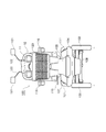
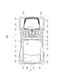
図1は本発明の実施形態に係る小型電動車両の全体構成を示す側面図、図2は正面図、図3は平面図である。小型電動車両100において、車体フレーム101に左右一対の前輪102および左右一対の後輪103が、サスペンションを介して支持される。車体フレーム101はその一部を除き、前部カバー104、レッグシールド105、フロア106および後部カバー107等からなる樹脂製カバーによって覆われる。
Hereinafter, preferred embodiments of an emergency stop device for a small electric vehicle according to the present invention will be described with reference to the drawings.
FIG. 1 is a side view showing the overall configuration of a small electric vehicle according to an embodiment of the present invention, FIG. 2 is a front view, and FIG. 3 is a plan view. In the small
車体後部において概略箱状もしくは箱型の後部カバー107が上方に突設され、後部カバー107の内側には後輪103を駆動するための駆動モータ108や駆動モータ108の出力を車軸109に伝達するギヤユニット110(図2あるいは図3等参照)、さらにバッテリおよびその充電器等を含む動力装置が収容されている。この動力装置は、制御装置により制御されるようになっている。
A substantially box-shaped or box-shaped
後部カバー107の上側には、車体フレーム101からたとえば門型に立ち上がるブラケット111を介して、搭乗者が着座するシート112が搭載される。シート112はシートクッション113とシートバック(背もたれ)114を含み、後部カバー107上で水平方向に旋回可能に支持される。なお、この旋回角度は車体センタから左右にたとえば45度および90度等に設定され、シートクッション113の両側部に付設された操作レバー115の操作で適宜旋回させることができる。
On the upper side of the
さらに、シートバック114の両側部にはアームレスト116が設けられ、各アームレスト116は、支点117のまわりに回動可能に支持される。各アームレスト116の側面にはそれぞれウィンカ118が配設される。また、シートバック114の背面には、後述するように把持部119が設けられる。
Furthermore,
レッグシールド105は車体前部で上方に突設され、シート112に着座した搭乗者の脚まわりを風等があたらないように保護する。レッグシールド105の内部には前輪102を操舵するためのステアリングシャフト120が立設されており、該ステアリングシャフト120の上端には、後述するハンドルユニット10が回動可能に取り付けられる。運転者は図1に示されるように、シート112に着座してハンドルユニット10を操作するようになっている。また、ハンドルユニット10の適所には、左右一対のバックミラー121がステー122を介して支持される。
The
レッグシールド105の前面部には収納籠もしくはキャリヤケース123が装架され、該キャリヤケース123を適宜物入れとして使用することができる。なお、キャリヤケース123の下方適所にヘッドライトが取り付けられる。
A storage box or
ここで、本発明に係る小型電動車両100において、ハンドルユニット10の具体的構成例について説明する。車体前部に立設されたステアリングシャフト120の上部は、図1のように後方へ適度に傾斜しており、その上端にハンドルユニット10が支持される。また、シート112の前方に位置するハンドルユニット10は、水平から運転者側へ適度に傾斜して配置される。
Here, a specific configuration example of the
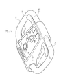
図4に示されるようにハンドル11は概略ループ状に形成され、後述するハンドルベースを介してその中央部付近で(図5)、ステアリングシャフト120によって下側から支持される。ハンドル11の前後をまたいで中央に、各種コントロールスイッチ等を搭載したスイッチボックス12が設けられる。スイッチボックス12の略平坦な上面には、最大速度設定スイッチ13、前進・後進切替えスイッチ14および左右ウィンカスイッチ15a,15bが中央部前後方向に沿って配置される。また、スイッチボックス12の上面前部には、各種表示ランプが点灯するようにしたインジケータ16が列設される。
As shown in FIG. 4, the
スイッチボックス12の内部には後述するアクセル機構部が収容され、アクセルレバー17と相俟ってアクセル操作を行い得るようになっている。この実施形態ではスイッチボックス12の両側に左右一対のアクセルレバー17を備え、いずれのアクセルレバー17でもアクセル操作可能になっている。
An accelerator mechanism, which will be described later, is housed inside the
図6は、アクセル機構部まわりを示している。ここで、ハンドル11は内部のパイプ材11Aの外側にハンドルグリップ11Bが外嵌する2重構造を有し、中央部前後にハンドルベース18(支持板)が架け渡され、ハンドル11と一体的に結合している。ハンドルベース18は前述のようにステアリングシャフト120と結合しており、したがってハンドル11の操作でステアリングシャフト120を回転し、これにより操舵機構(図示せず)を介して左右の前輪102を操舵することができる。
FIG. 6 shows the area around the accelerator mechanism. Here, the
ハンドルベース18上内側にアクセル機構部19全体が、支軸20を介して回動可能に支持される。なお、アクセル機構部19の回動角度は後述するように、緊急停止装置を作動させるに足れば十分であり、実際にはその可動範囲は数度程度である。アクセル機構部19には左右方向にアクセルレバー軸21が回転可能に支持され、アクセル機構部19から延出する各アクセルレバー軸21の端部にはアクセルレバー17が取り付けられる。アクセルレバー17はアクセルレバー軸21のまわりに回動する。通常操作では図5のように、実線で示される初期位置(アクセル全閉位置)と2点鎖線で示される回動位置(アクセル全開位置)の間を往復動する。
The
アクセルレバー軸21にはドライブギヤ22が取り付けられ、ドライブギヤ22はドリブンギヤ23と噛合する。ドリブンギヤ23の軸24はポテンショメータ25に連結し、したがってアクセルレバー軸21の回転によりドライブギヤ22およびドリブンギヤ23を介して、その回転量に応じてポテンショメータ25が駆動される。ポテンショメータ25の出力はメインコントローラ(図示せず)に送出され、このメインコントローラからの制御信号により駆動モータ108が駆動されるようになっている。
A
アクセルレバー軸21にはまた、リターンスプリング26が装着されている。リターンスプリング26はその弾力により、アクセルレバー軸21、したがってアクセルレバー17をその初期位置方向へ回動付勢する。アクセルレバー17に入力がない限り、初期位置に自動復帰するようになっている。この場合、アクセルレバー軸21上にはストッパ27(この例では略矩形状のプレート)が取り付けられている。ストッパ27は図7に示されるように、その両端部27a,27bでハンドルベース18に当接し、それぞれの当接位置でアクセルレバー17の全閉位置および全開位置が規定される。
A
なおここで、上述したドライブギヤ22、ドリブンギヤ23、軸24、ポテンショメータ25、リターンスプリング26およびストッパ27の各部材は、アクセル信号変換機構を構成する。
Here, the
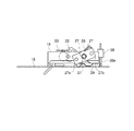
前述したようにアクセル機構部19は支軸20を介して、ハンドルベース18に対して回動もしくは揺動可能に支持される。詳しくは後述するものとするが、緊急停止時には図8のように支軸20のまわりに回動することで、ハンドルベース18(あるいはハンドル11)に対して傾動する。なお、通常操作時にはアクセル機構部19は、後述するリターンスプリングによりハンドルベース18と略平行に保持される。
As described above, the
アクセル機構部19の端部(運転者側)には図8等に示されるように、その接点28aがハンドルベース18もしくはその付属物に接触することにより作動するスイッチ28が設けられており、スイッチ28の作動でアクセル機構部19の傾動を検出することができる。スイッチ28の出力はメインコントローラに送出され、このメインコントローラからの制御信号により駆動モータ108の電磁ブレーキが作動して車両が停止するようになっている。なお、アクセル機構部19の下面にはリターンスプリング29が装着されていて、傾動したアクセル機構部19を元の状態(位置)に復帰させることができる。
As shown in FIG. 8 or the like, an end of the accelerator mechanism 19 (driver side) is provided with a
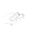
さて、上記構成の小型電動車両100の実使用において、シート112に着座した運転者は図1に示されるようにハンドルユニット10のハンドル11を持ち、あるいは軽く手を掛け、該ハンドル11に装着されたアクセルレバー17を操作することで車両を走行させることができる。すなわち、走行中のアクセル操作では図9のようにハンドルグリップ11B(握り部)に手を置いた状態で、手指でアクセルレバー17を軽く下方に押すことで走行することができる。その際、アクセルレバー17の押し加減を適宜調節することで、増速あるいは減速しスピードがコントロールされる。
Now, in actual use of the small
図8に示すように車両停車時にはアクセルレバー17の操作部17A(手指で押す部分)は、点線で示される初期位置にあり、該操作部17Aを押すとアクセル信号変換機構を介してポテンショメータ25からメインコントローラへ信号が送出され、その信号に応じて駆動モータ108が駆動される。そして、実線で示されるアクセル全開位置まで回動することで、そのときの最大速度が得られる。
As shown in FIG. 8, when the vehicle is stopped, the
ストッパ27の端部27bがハンドルベース18に当接するアクセル全開位置で、アクセルレバー17がフルストロークになるように設定されているが、このときアクセルレバー17の操作部17Aの上面と、ハンドルグリップ11Bの上面とが略水平になる。アクセルレバー17をフルストロークからさらに押下げ操作することで、アクセル機構部19がその支軸20のまわりに2点鎖線のように揺動する。アクセル機構部19の揺動によりスイッチ28の接点28aがハンドルベース18に接触し、スイッチ28がONしてアクセル機構部19が傾動したことを検出することができる。スイッチ28の出力はメインコントローラに送出され、このメインコントローラからの制御信号により駆動モータ108の電磁ブレーキが作動して車両が停止する。
The
このときアクセルレバー17の操作部17Aは、図8の2点鎖線のように支軸20を中心とする回動軌跡に沿って回動する。このようにアクセルレバー17の回動中心が、アクセルレバー軸21から支軸20へシフトすることで、フルストロークに達するまでのアクセルレバー軸21を中心とする回動軌跡よりも前方側の軌跡を通る。したがって、全開位置にあるアクセルレバー17がハンドルグリップ11B直近まで接近し、あるいは一部接するように設定しても、その後アクセルレバー17がハンドルグリップ11Bから逃げる軌跡とように支軸20を配置することで、むやみに緊急停止機構が働かないようにしている。
At this time, the
すなわち、この実施形態では特に図8に示したように、アクセルレバー17のフルストローク時におけるその操作部17Aおよびハンドル11のハンドルグリップ11Bのそれぞれ中心を通る仮想軸線Aと、アクセルレバー17の操作部17Aおよび支軸20のそれぞれ中心を通る軸線Bとがなす第1の交差角度αが、仮想軸線Aとアクセルレバー17の操作部17Aおよびアクセルレバー軸21のそれぞれ中心を通る軸線Cとがなす第2の交差角度βよりも鋭角度になるように、アクセル機構部19の支軸20が配置される。
That is, in this embodiment, as particularly shown in FIG. 8, the virtual axis A passing through the centers of the
支軸20をこのように配置することで、前述のように通常操作時と緊急停止時でアクセルレバー17の回動軌跡を変更する。すなわち、通常操作時と緊急停止時のアクセルレバー17の操作方向を異ならせ、アクセルレバー17の操作部17Aをハンドルグリップ11Bにより接近して配置することができる。また、これにより緊急停止機構が不用意に作動するのを防止するとともに、緊急停止時の動作方向が通常操作時の延長上にあるようにすることで、咄嗟の場合にも迅速に対応操作することができる。
By disposing the
また、アクセル全開位置でアクセルレバー17の操作部17Aの上面とハンドルグリップ11Bの上面とが略水平になり、アクセルレバー17をさらに押下げ操作することで緊急停止機構が作動する。このようにアクセルレバー17の通常操作領域と緊急停止操作領域をハンドルグリップ11B上面の上方とそれよりも下方の領域で分割することにより、この点でも緊急停止機構が不用意に作動するのを防止することができる。
Further, the upper surface of the
ここで、アクセルレバー17およびアクセルレバー軸21とアクセル信号変換機構とを一体のアクセル機構部19に形成し、これにより余組付けが可能になり、組立て性が向上する。
また、アクセルレバー軸21およびアクセル信号変換機構を、緊急停止機構の支軸20とは別体に構成したことで、アクセル機構部19の耐久性を向上することができる。
Here, the
Further, since the
以上、本発明を実施形態とともに説明したが、本発明はこれらの実施形態にのみ限定されるものではなく、本発明の範囲内で変更等が可能である。
たとえば、本実施形態ではスイッチボックス12の両側に左右一対のアクセルレバー17を備えた例を説明したが、いずれか一方の側のみアクセルレバー17を設けてもよい。
また、本発明は三輪または四輪の小型電動車両の他に、電動車椅子(モータチェアタイプ)に対しても有効に適用可能であり、上記実施形態と同様な作用効果を得ることができる。
As mentioned above, although this invention was demonstrated with embodiment, this invention is not limited only to these embodiment, A change etc. are possible within the scope of the present invention.
For example, in the present embodiment, an example in which a pair of left and right accelerator levers 17 are provided on both sides of the
Further, the present invention can be effectively applied to an electric wheelchair (motor chair type) in addition to a three-wheel or four-wheel small electric vehicle, and the same effects as those of the above embodiment can be obtained.
10 ハンドルユニット
11 ハンドル
12 スイッチボックス
17 アクセルレバー
18 ハンドルベース
19 アクセル機構部
20 支軸
21 アクセルレバー軸
22 ドライブギヤ
23 ドリブンギヤ
25 ポテンショメータ
26 リターンスプリング
27 ストッパ
28 スイッチ
29 リターンスプリング
100 小型電動車両
101 車体フレーム
102 前輪
103 後輪
104 前部カバー
105 レッグシールド
106 フロア
107 後部カバー
108 駆動モータ
109 車軸
110 ギヤユニット
112 シート
113 シートクッション
114 シートバック
116 アームレスト
118 ウィンカ
119 把持部
120 ステアリングシャフト
121 バックミラー
123 キャリヤケース
10
Claims (6)
アクセルレバーの動きを電気信号に変換するためのアクセル信号変換機構を有するアクセル機構部が、操向ハンドルに対して揺動可能に支持され、前記アクセルレバーがアクセルレバー軸のまわりに回動する際、前記アクセルレバーが設定ストローク以上に操作されたとき前記アクセル機構部がその支軸のまわりを揺動し、緊急停止検出スイッチが作動するようにしたことを特徴とする小型電動車両の緊急停止装置。 An emergency stop device for a small electric vehicle in a small electric vehicle in which an electric motor and a battery are mounted on a vehicle body frame to which a wheel and a driver seat are attached, and the wheel is driven by the electric motor,
An accelerator mechanism having an accelerator signal conversion mechanism for converting the movement of the accelerator lever into an electric signal is supported so as to be swingable with respect to the steering handle, and the accelerator lever rotates around the accelerator lever shaft. An emergency stop device for a small electric vehicle characterized in that when the accelerator lever is operated more than a set stroke, the accelerator mechanism swings around its support shaft and an emergency stop detection switch is activated. .
Priority Applications (1)
| Application Number | Priority Date | Filing Date | Title |
|---|---|---|---|
| JP2004290626A JP4631381B2 (en) | 2004-10-01 | 2004-10-01 | Emergency stop device for small electric vehicles |
Applications Claiming Priority (1)
| Application Number | Priority Date | Filing Date | Title |
|---|---|---|---|
| JP2004290626A JP4631381B2 (en) | 2004-10-01 | 2004-10-01 | Emergency stop device for small electric vehicles |
Publications (2)
| Publication Number | Publication Date |
|---|---|
| JP2006102003A true JP2006102003A (en) | 2006-04-20 |
| JP4631381B2 JP4631381B2 (en) | 2011-02-16 |
Family
ID=36372390
Family Applications (1)
| Application Number | Title | Priority Date | Filing Date |
|---|---|---|---|
| JP2004290626A Expired - Fee Related JP4631381B2 (en) | 2004-10-01 | 2004-10-01 | Emergency stop device for small electric vehicles |
Country Status (1)
| Country | Link |
|---|---|
| JP (1) | JP4631381B2 (en) |
Cited By (3)
| Publication number | Priority date | Publication date | Assignee | Title |
|---|---|---|---|---|
| WO2007058029A1 (en) * | 2005-11-16 | 2007-05-24 | Honda Motor Co., Ltd. | Steering device of small-sized electric vehicle |
| CN115303349A (en) * | 2022-08-04 | 2022-11-08 | 江苏金飞达电动工具有限公司 | Switch device with emergency brake |
| JP2023150134A (en) * | 2022-03-31 | 2023-10-16 | ヤマハ発動機株式会社 | Motor control systems, drive units and electric vehicles |
Citations (5)
| Publication number | Priority date | Publication date | Assignee | Title |
|---|---|---|---|---|
| JPS6096249A (en) * | 1983-10-31 | 1985-05-29 | スズキ株式会社 | Electromotive wheelchair |
| JPH0168031U (en) * | 1987-10-27 | 1989-05-01 | ||
| JPH0451932U (en) * | 1990-09-11 | 1992-05-01 | ||
| JPH0796009A (en) * | 1993-09-30 | 1995-04-11 | Suzuki Motor Corp | Electric tricycle |
| JP2000051276A (en) * | 1998-08-03 | 2000-02-22 | Honda Motor Co Ltd | Emergency stop mechanism for electric passenger cars |
-
2004
- 2004-10-01 JP JP2004290626A patent/JP4631381B2/en not_active Expired - Fee Related
Patent Citations (5)
| Publication number | Priority date | Publication date | Assignee | Title |
|---|---|---|---|---|
| JPS6096249A (en) * | 1983-10-31 | 1985-05-29 | スズキ株式会社 | Electromotive wheelchair |
| JPH0168031U (en) * | 1987-10-27 | 1989-05-01 | ||
| JPH0451932U (en) * | 1990-09-11 | 1992-05-01 | ||
| JPH0796009A (en) * | 1993-09-30 | 1995-04-11 | Suzuki Motor Corp | Electric tricycle |
| JP2000051276A (en) * | 1998-08-03 | 2000-02-22 | Honda Motor Co Ltd | Emergency stop mechanism for electric passenger cars |
Cited By (5)
| Publication number | Priority date | Publication date | Assignee | Title |
|---|---|---|---|---|
| WO2007058029A1 (en) * | 2005-11-16 | 2007-05-24 | Honda Motor Co., Ltd. | Steering device of small-sized electric vehicle |
| JP2023150134A (en) * | 2022-03-31 | 2023-10-16 | ヤマハ発動機株式会社 | Motor control systems, drive units and electric vehicles |
| JP7746211B2 (en) | 2022-03-31 | 2025-09-30 | ヤマハ発動機株式会社 | Motor control system, drive unit and electric vehicle |
| CN115303349A (en) * | 2022-08-04 | 2022-11-08 | 江苏金飞达电动工具有限公司 | Switch device with emergency brake |
| CN115303349B (en) * | 2022-08-04 | 2024-02-02 | 江苏金飞达电动工具有限公司 | Switchgear with emergency brake |
Also Published As
| Publication number | Publication date |
|---|---|
| JP4631381B2 (en) | 2011-02-16 |
Similar Documents
| Publication | Publication Date | Title |
|---|---|---|
| JP6380485B2 (en) | Traveling device | |
| KR101531278B1 (en) | Automatic folding electronic car | |
| JP4529629B2 (en) | Direction indicator for small electric vehicle | |
| CN211663322U (en) | Foot control panels, cabs, foot control systems and foot control vehicles | |
| JP4631381B2 (en) | Emergency stop device for small electric vehicles | |
| JP2018061305A (en) | Accelerator device for electric vehicle | |
| JP2010208413A (en) | Emergency stop mechanism for electric vehicle | |
| JP3313457B2 (en) | Accelerator operation structure of small electric vehicle | |
| JP2000118275A (en) | Vehicular seat | |
| JP6759939B2 (en) | Accelerator device for electric vehicles | |
| JP2002220196A (en) | Forklift operating lever and forklift | |
| JPH10165454A (en) | Small electric car | |
| JP7458632B2 (en) | electric bike | |
| JP2006130302A (en) | Small electric vehicle and handle unit | |
| JP4552226B2 (en) | Electric wheelchair accelerator lever | |
| JP2006103511A (en) | Small electric vehicle and handle unit | |
| JP3772673B2 (en) | Accelerator device for electric vehicle | |
| JP3124825U (en) | wheelchair | |
| JP2000264104A (en) | Seat support device of electric vehicle | |
| JP3605814B2 (en) | Control device for walking electric vehicle | |
| JP2006168484A5 (en) | ||
| JP2026044151A (en) | Electric vehicles | |
| JP2018196576A (en) | Electric vehicle | |
| JP6880716B2 (en) | Accelerator device for small electric vehicles | |
| JP3509434B2 (en) | Small electric car |
Legal Events
| Date | Code | Title | Description |
|---|---|---|---|
| A621 | Written request for application examination |
Free format text: JAPANESE INTERMEDIATE CODE: A621 Effective date: 20070928 |
|
| A131 | Notification of reasons for refusal |
Free format text: JAPANESE INTERMEDIATE CODE: A131 Effective date: 20100316 |
|
| A977 | Report on retrieval |
Free format text: JAPANESE INTERMEDIATE CODE: A971007 Effective date: 20100318 |
|
| A521 | Request for written amendment filed |
Free format text: JAPANESE INTERMEDIATE CODE: A523 Effective date: 20100514 |
|
| TRDD | Decision of grant or rejection written | ||
| A01 | Written decision to grant a patent or to grant a registration (utility model) |
Free format text: JAPANESE INTERMEDIATE CODE: A01 Effective date: 20101019 |
|
| A01 | Written decision to grant a patent or to grant a registration (utility model) |
Free format text: JAPANESE INTERMEDIATE CODE: A01 |
|
| A61 | First payment of annual fees (during grant procedure) |
Free format text: JAPANESE INTERMEDIATE CODE: A61 Effective date: 20101101 |
|
| R151 | Written notification of patent or utility model registration |
Ref document number: 4631381 Country of ref document: JP Free format text: JAPANESE INTERMEDIATE CODE: R151 |
|
| FPAY | Renewal fee payment (event date is renewal date of database) |
Free format text: PAYMENT UNTIL: 20131126 Year of fee payment: 3 |
|
| LAPS | Cancellation because of no payment of annual fees |