JP2006105145A - 噴射ノズル - Google Patents
噴射ノズル Download PDFInfo
- Publication number
- JP2006105145A JP2006105145A JP2005290051A JP2005290051A JP2006105145A JP 2006105145 A JP2006105145 A JP 2006105145A JP 2005290051 A JP2005290051 A JP 2005290051A JP 2005290051 A JP2005290051 A JP 2005290051A JP 2006105145 A JP2006105145 A JP 2006105145A
- Authority
- JP
- Japan
- Prior art keywords
- valve member
- seat
- inner valve
- outer valve
- nozzle
- Prior art date
- Legal status (The legal status is an assumption and is not a legal conclusion. Google has not performed a legal analysis and makes no representation as to the accuracy of the status listed.)
- Granted
Links
Images






Classifications
-
- F—MECHANICAL ENGINEERING; LIGHTING; HEATING; WEAPONS; BLASTING
- F02—COMBUSTION ENGINES; HOT-GAS OR COMBUSTION-PRODUCT ENGINE PLANTS
- F02M—SUPPLYING COMBUSTION ENGINES IN GENERAL WITH COMBUSTIBLE MIXTURES OR CONSTITUENTS THEREOF
- F02M61/00—Fuel-injectors not provided for in groups F02M39/00 - F02M57/00 or F02M67/00
- F02M61/16—Details not provided for in, or of interest apart from, the apparatus of groups F02M61/02 - F02M61/14
- F02M61/18—Injection nozzles, e.g. having valve seats; Details of valve member seated ends, not otherwise provided for
- F02M61/1806—Injection nozzles, e.g. having valve seats; Details of valve member seated ends, not otherwise provided for characterised by the arrangement of discharge orifices, e.g. orientation or size
- F02M61/182—Discharge orifices being situated in different transversal planes with respect to valve member direction of movement
-
- F—MECHANICAL ENGINEERING; LIGHTING; HEATING; WEAPONS; BLASTING
- F02—COMBUSTION ENGINES; HOT-GAS OR COMBUSTION-PRODUCT ENGINE PLANTS
- F02M—SUPPLYING COMBUSTION ENGINES IN GENERAL WITH COMBUSTIBLE MIXTURES OR CONSTITUENTS THEREOF
- F02M45/00—Fuel-injection apparatus characterised by having a cyclic delivery of specific time/pressure or time/quantity relationship
- F02M45/02—Fuel-injection apparatus characterised by having a cyclic delivery of specific time/pressure or time/quantity relationship with each cyclic delivery being separated into two or more parts
- F02M45/04—Fuel-injection apparatus characterised by having a cyclic delivery of specific time/pressure or time/quantity relationship with each cyclic delivery being separated into two or more parts with a small initial part, e.g. initial part for partial load and initial and main part for full load
- F02M45/08—Injectors peculiar thereto
- F02M45/086—Having more than one injection-valve controlling discharge orifices
-
- F—MECHANICAL ENGINEERING; LIGHTING; HEATING; WEAPONS; BLASTING
- F02—COMBUSTION ENGINES; HOT-GAS OR COMBUSTION-PRODUCT ENGINE PLANTS
- F02M—SUPPLYING COMBUSTION ENGINES IN GENERAL WITH COMBUSTIBLE MIXTURES OR CONSTITUENTS THEREOF
- F02M51/00—Fuel-injection apparatus characterised by being operated electrically
- F02M51/06—Injectors peculiar thereto with means directly operating the valve needle
- F02M51/0603—Injectors peculiar thereto with means directly operating the valve needle using piezoelectric or magnetostrictive operating means
-
- F—MECHANICAL ENGINEERING; LIGHTING; HEATING; WEAPONS; BLASTING
- F02—COMBUSTION ENGINES; HOT-GAS OR COMBUSTION-PRODUCT ENGINE PLANTS
- F02M—SUPPLYING COMBUSTION ENGINES IN GENERAL WITH COMBUSTIBLE MIXTURES OR CONSTITUENTS THEREOF
- F02M61/00—Fuel-injectors not provided for in groups F02M39/00 - F02M57/00 or F02M67/00
- F02M61/16—Details not provided for in, or of interest apart from, the apparatus of groups F02M61/02 - F02M61/14
- F02M61/18—Injection nozzles, e.g. having valve seats; Details of valve member seated ends, not otherwise provided for
-
- F—MECHANICAL ENGINEERING; LIGHTING; HEATING; WEAPONS; BLASTING
- F02—COMBUSTION ENGINES; HOT-GAS OR COMBUSTION-PRODUCT ENGINE PLANTS
- F02M—SUPPLYING COMBUSTION ENGINES IN GENERAL WITH COMBUSTIBLE MIXTURES OR CONSTITUENTS THEREOF
- F02M2200/00—Details of fuel-injection apparatus, not otherwise provided for
- F02M2200/46—Valves, e.g. injectors, with concentric valve bodies
-
- F—MECHANICAL ENGINEERING; LIGHTING; HEATING; WEAPONS; BLASTING
- F02—COMBUSTION ENGINES; HOT-GAS OR COMBUSTION-PRODUCT ENGINE PLANTS
- F02M—SUPPLYING COMBUSTION ENGINES IN GENERAL WITH COMBUSTIBLE MIXTURES OR CONSTITUENTS THEREOF
- F02M61/00—Fuel-injectors not provided for in groups F02M39/00 - F02M57/00 or F02M67/00
- F02M61/04—Fuel-injectors not provided for in groups F02M39/00 - F02M57/00 or F02M67/00 having valves, e.g. having a plurality of valves in series
- F02M61/042—The valves being provided with fuel passages
Landscapes
- Engineering & Computer Science (AREA)
- Chemical & Material Sciences (AREA)
- Combustion & Propulsion (AREA)
- Mechanical Engineering (AREA)
- General Engineering & Computer Science (AREA)
- Fuel-Injection Apparatus (AREA)
- Lubrication Of Internal Combustion Engines (AREA)
Abstract
【解決手段】内燃機関用の噴射ノズル4は、弁座面22を画成する孔8を備え、かつ第1ノズル出口12と第2ノズル出口18とを有するノズル本体6と、ノズル出口12,18の上流側の第1供給室50と、孔8内において移動可能で、それ自体が軸方向孔16を備える外側弁部材10であって、外側弁部材10がそのシート24から持ち上がるときに、第1供給室50から少なくとも第1ノズル出口12への燃料流れを制御するように、弁座面22によって画成された外側弁シート24と係合可能である外側弁部材10とを備えている。
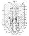
【選択図】図3
Description
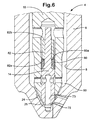
4 噴射ノズル
6 ノズル本体
7 環状室
8 軸方向止まり孔
10 外側弁ニードル
10a 上端領域
10b 下端領域
10c 上側シート領域
10d 上側溝領域
10e 下側溝領域
10f 端領域
11 第1(上側)シートライン
12 第1出口
13 第2(下側)シートライン
14 内側弁ニードル
14a 上側ステム領域
14b 段領域
14c 下側領域
14d 上側溝領域
14e 下側溝領域
14f 先端領域
14g 上側シート領域
15 段(肩)
16 軸方向孔
18 第2出口
20 嚢容積部(第2供給室)
22a 座面
24 外側弁座部
25 内側弁座部
25a 第1シート
25b 第2シート
26 第1閉鎖バネ
26a バネ室
30 圧電アクチェータ
32 積層体
34 蓄圧容積部
38 入口通路
39 入口
40 電気コネクタ
42 液圧増幅装置
50 第1供給室
52 半径方向通路
53 半径方向通路
62 チャンバー
64 環状容積部
70 半径方向ドリル孔
72 止まり孔
73 上側シートライン
75 下側シートライン
77 環状容積部
80 リング
80a 第1上端面
80b 第2下端面
82 スリーブ
82a 第1下端面
82b 上端面
90 平面(凹部)
92 チャンバー
L 距離
Claims (16)
- 内燃機関用の噴射ノズル(4)において、
弁座面(22)を画成する孔(8)を備えるノズル本体(6)であって、第1ノズル出口(12)と第2ノズル出口(18)とを有するノズル本体(6)と、
前記ノズル出口(12,18)の上流側の第1供給室(50)と、
前記孔(8)内において移動可能で、それ自体が軸方向孔(16)を備える外側弁部材(10)であって、前記外側弁ニードル(10)がそのシート(24)から持ち上がるときに、前記第1供給室(50)から少なくとも前記第1ノズル出口(12)への燃料流れを制御するように、前記弁座面(22)によって画成された外側弁シート(24)と係合可能である外側弁ニードル(10)と、
前記軸方向孔(16)内において移動可能で、互いに軸方向に離間された第1及び第2シートライン(73,75)を備える内側弁部材(14)であって、前記両シートライン(73,75)は、前記内側弁部材(14)が前記弁座面(22)によって画成された内側弁シート(25)から持ち上がるときに、第2供給室(20)から前記第2ノズル出口(18)への燃料流れを制御するように、前記内側弁シート(25)と係合可能であり、前記内側弁部材(14)は、燃料が前記第1供給室(50)から前記第2供給室(20)に流れ得るように、前記内側弁部材(14)に設けられた軸方向通路(72)を備える流路手段(52,70,72)を少なくとも部分的に画成するような内側弁部材(14)と、
を備えていることを特徴とする噴射ノズル。 - 前記内側弁シート(25)は、それぞれ、前記第2出口(12)の軸方向において上側と下側に配置された第1及び第2シート(25a、25b)を備えていることを特徴とする、請求項1に記載の噴射ノズル。
- 前記流路手段は、前記内側弁部材に設けられた少なくとも1つの半径方向通路を備えていることを特徴とする、請求項1または2に記載の噴射ノズル。
- 前記流路手段は、前記外側弁ニードル(10)に設けられた少なくとも1つの半径方向通路(52)を備えていることを特徴とする、請求項1〜3のいずれか一項に記載の噴射ノズル。
- 前記第1及び第2シートライン(73,75)は、前記内側弁部材(14)に設けられた環状溝によって、少なくとも部分的に画成されていることを特徴とする、請求項1〜4のいずれか一項に記載の噴射ノズル。
- 前記外側弁部材(10)は、前記外側弁座部(24)によって画成された第1及び第2シート(24a,24b)と係合する第1及び第2シートライン(11,13)を画成し、前記第1及び第2シート(24a,24b)は、それぞれ、前記第1出口(12)の軸方向において上側及び下側に配置されていることを特徴とする、請求項1〜5のいずれか一項に記載の噴射ノズル。
- 前記第1及び第2シートライン(11,13)は、前記外側弁部材(10)に設けられた環状溝によって、少なくとも部分的に画成されていることを特徴とする、請求項6に記載の噴射ノズル。
- 前記内側弁部材(14)に連結されたスリーブ部材(82)と、前記外側弁部材(10)に連結されたリング部材(80)とをさらに備え、前記リング部材(80)は、前記外側弁部材(10)が所定距離(L)よりも大きい距離だけ軸方向に移動して前記内側弁部材(14)に軸方向運動を与えるとき、前記スリーブ部材(82)と係合するようになっていることを特徴とする、請求項1〜7のいずれか一項に記載の噴射ノズル。
- 前記リング部材(80)と前記スリーブ部材(82)は、それぞれ、第1及び第2端面(80a,80b;82a,82b)を有し、前記リング部材(80)の前記第1端面(80a)は、前記スリーブ部材(82)の前記第1端面(82a)と対向し、前記外側弁部材(10)と前記内側弁部材(14)が着座したとき、前記スリーブ部材(82)の前記第1端面(82a)から前記所定距離(L)だけ離間するようになっていることを特徴とする、請求項8に記載の噴射ノズル。
- 前記リング部材(80)の前記第2端面(80b)は、前記内側弁部材(14)によって設けられた肩(15)と当接していることを特徴とする、請求項9に記載の噴射ノズル。
- 内燃機関用の噴射ノズル(4)において、
弁座面(22)を画成する孔(8)を備えるノズル本体(6)であって、第1ノズル出口(12)と第2ノズル出口(18)とを有するノズル本体(6)と、
前記ノズル出口(12,18)の上流側の第1供給室(50)と、
前記孔(8)内において移動可能であり、それ自体が軸方向孔(16)を備える外側弁部材(10)であって、前記外側弁部材(10)がそのシート(24)から持ち上がるときに、前記第1供給室(50)から少なくとも前記第1ノズル出口(12)への燃料流れを制御するように、前記弁座面(22)によって画成された外側弁シート(24)と係合可能である外側弁部材(10)と、
前記軸方向孔(16)内において移動可能で、互いに軸方向において離間される第1及び第2シートライン(73,75)を備える内側弁部材(14)であって、前記両シートライン(73,75)は、前記内側弁部材(14)が前記弁座面(22)によって画成された内側弁シート(25)から持ち上がるときに、第2供給室(20)から前記第2ノズル出口(18)への燃料流れを制御するように、前記内側弁シート(25)と係合可能であるような内側弁ニードル(14)と、
前記外側弁部材(10)が所定距離(L)よりも大きい距離だけ軸方向に移動したときに、前記外側弁部材(10)を前記内側弁部材(14)に連結するように構成された連結手段であって、前記内側弁部材(14)は、燃料が前記第1供給室(50)から前記第2供給室(20)に流れ得るように、前記内側弁部材(14)内に設けられた軸方向通路(72)を備える流路手段(52,70,72)を少なくとも部分的に画成するような連結手段と、
を備えていることを特徴とする噴射ノズル。 - 前記連結手段は、前記内側弁部材(14)に連結されたスリーブ部材(82)と、前記外側弁部材(10)に連結されたリング部材(80)とを備え、前記リング部材(80)は、前記外側弁部材(10)が所定距離(L)よりも大きい距離だけ軸方向に移動して前記内側弁部材(14)に軸方向運動を与えるとき、前記スリーブ部材(82)と係合するようになっていることを特徴とする、請求項11に記載の噴射ノズル。
- 前記リング部材(80)と前記スリーブ部材(82)は、それぞれ、第1及び第2端面(80a,80b;82a,82b)を有し、前記リング部材(80)の前記第1端面(80a)は、前記スリーブ部材(82)の前記第1端面(82a)と対向し、前記外側弁部材(10)と前記内側弁部材(14)が着座したとき、前記スリーブ部材(82)の前記第1端面(82a)から前記所定距離(L)だけ離間するようになっていることを特徴とする、請求項12に記載の噴射ノズル。
- 前記リング部材(80)の前記第2端面(80b)は、前記内側弁部材(14)によって設けられた肩(15)と当接することを特徴とする、請求項13に記載の噴射ノズル。
- 内燃機関に用いられる噴射器(2)において、請求項1〜14のいずれか一項に記載の噴射ノズル(4)と、前記外側弁部材(10)の軸方向移動を制御するためのアクチェータ(30)とを備えていることを特徴とする噴射器。
- 前記アクチェータは、圧電アクチェータ(30)であることを特徴とする、請求項15に記載の噴射器。
Applications Claiming Priority (1)
| Application Number | Priority Date | Filing Date | Title |
|---|---|---|---|
| EP04256105A EP1643117B1 (en) | 2004-10-01 | 2004-10-01 | Injection nozzle |
Publications (2)
| Publication Number | Publication Date |
|---|---|
| JP2006105145A true JP2006105145A (ja) | 2006-04-20 |
| JP4224481B2 JP4224481B2 (ja) | 2009-02-12 |
Family
ID=34930714
Family Applications (1)
| Application Number | Title | Priority Date | Filing Date |
|---|---|---|---|
| JP2005290051A Expired - Fee Related JP4224481B2 (ja) | 2004-10-01 | 2005-10-03 | 噴射器 |
Country Status (5)
| Country | Link |
|---|---|
| US (1) | US7523875B2 (ja) |
| EP (1) | EP1643117B1 (ja) |
| JP (1) | JP4224481B2 (ja) |
| AT (1) | ATE371809T1 (ja) |
| DE (1) | DE602004008630T2 (ja) |
Cited By (2)
| Publication number | Priority date | Publication date | Assignee | Title |
|---|---|---|---|---|
| JP2009506254A (ja) * | 2005-08-25 | 2009-02-12 | キャタピラー インコーポレイテッド | 溝付逆止部材を備えた燃料噴射器 |
| JP2013144990A (ja) * | 2013-04-25 | 2013-07-25 | Denso Corp | 燃料噴射弁 |
Families Citing this family (6)
| Publication number | Priority date | Publication date | Assignee | Title |
|---|---|---|---|---|
| CN101825033B (zh) * | 2010-02-04 | 2013-06-26 | 大连理工大学 | 点火室式直喷汽油机的燃料喷射方法 |
| GB201421885D0 (en) * | 2014-12-09 | 2015-01-21 | Delphi International Operations Luxembourg S.�.R.L. | Fuel injector |
| JP6439753B2 (ja) * | 2016-06-08 | 2018-12-19 | トヨタ自動車株式会社 | 内燃機関 |
| JP6436133B2 (ja) * | 2016-06-08 | 2018-12-12 | トヨタ自動車株式会社 | 内燃機関 |
| WO2023166139A1 (de) * | 2022-03-03 | 2023-09-07 | Ganser-Hydromag Ag | Brennstoffeinspritzventil für verbrennungskraftmaschinen |
| GB2630647B (en) * | 2023-06-02 | 2025-07-02 | Phinia Delphi Luxembourg Sarl | Fuel injector |
Family Cites Families (11)
| Publication number | Priority date | Publication date | Assignee | Title |
|---|---|---|---|---|
| GB1565210A (en) * | 1975-10-21 | 1980-04-16 | Lucas Industries Ltd | Fuel injection nozzles for direct injection internal combustion engine |
| FR2328855A1 (fr) * | 1975-10-21 | 1977-05-20 | Lucas Industries Ltd | Injecteur de carburant liquide pour moteur |
| DE2710217A1 (de) * | 1977-03-09 | 1978-09-14 | Bosch Gmbh Robert | Kraftstoffeinspritzduese |
| US5899389A (en) * | 1997-06-02 | 1999-05-04 | Cummins Engine Company, Inc. | Two stage fuel injector nozzle assembly |
| DE69922087T2 (de) * | 1998-06-24 | 2005-12-01 | Delphi Technologies, Inc., Troy | Brennstoffeinspritzdüse |
| DE10034444A1 (de) * | 2000-07-15 | 2002-01-24 | Bosch Gmbh Robert | Brennstoffeinspritzventil |
| DE10122241A1 (de) * | 2001-05-08 | 2002-12-05 | Bosch Gmbh Robert | Kraftstoffeinspritzventil für Brennkraftmaschinen |
| DE10162651A1 (de) * | 2001-12-20 | 2003-09-04 | Bosch Gmbh Robert | Kraftstoffeinspritzeinrichtung für eine Brennkraftmaschine |
| DE10315821A1 (de) * | 2002-11-11 | 2004-05-27 | Robert Bosch Gmbh | Kraftstoffeinspritzventil für Brennkraftmaschinen |
| DE10306808A1 (de) * | 2003-02-18 | 2004-09-02 | Siemens Ag | Injektor zum Einspritzen von Kraftstoff |
| EP1626173B1 (en) * | 2004-08-13 | 2008-03-05 | Delphi Technologies, Inc. | Injection nozzle |
-
2004
- 2004-10-01 DE DE602004008630T patent/DE602004008630T2/de not_active Expired - Lifetime
- 2004-10-01 EP EP04256105A patent/EP1643117B1/en not_active Expired - Lifetime
- 2004-10-01 AT AT04256105T patent/ATE371809T1/de not_active IP Right Cessation
-
2005
- 2005-09-27 US US11/235,800 patent/US7523875B2/en not_active Expired - Fee Related
- 2005-10-03 JP JP2005290051A patent/JP4224481B2/ja not_active Expired - Fee Related
Cited By (2)
| Publication number | Priority date | Publication date | Assignee | Title |
|---|---|---|---|---|
| JP2009506254A (ja) * | 2005-08-25 | 2009-02-12 | キャタピラー インコーポレイテッド | 溝付逆止部材を備えた燃料噴射器 |
| JP2013144990A (ja) * | 2013-04-25 | 2013-07-25 | Denso Corp | 燃料噴射弁 |
Also Published As
| Publication number | Publication date |
|---|---|
| DE602004008630D1 (de) | 2007-10-11 |
| JP4224481B2 (ja) | 2009-02-12 |
| DE602004008630T2 (de) | 2008-06-12 |
| US20060071100A1 (en) | 2006-04-06 |
| EP1643117A1 (en) | 2006-04-05 |
| US7523875B2 (en) | 2009-04-28 |
| ATE371809T1 (de) | 2007-09-15 |
| EP1643117B1 (en) | 2007-08-29 |
Similar Documents
| Publication | Publication Date | Title |
|---|---|---|
| US6776354B2 (en) | Fuel injector | |
| JP4331225B2 (ja) | 内燃機関の燃料噴射制御装置 | |
| JP4194564B2 (ja) | 噴射ノズル | |
| JP4224481B2 (ja) | 噴射器 | |
| JP4180592B2 (ja) | 噴射ノズル | |
| JP4125295B2 (ja) | 噴射ノズル | |
| JP4215762B2 (ja) | 燃料噴射ノズル及びその製造方法 | |
| JP4856482B2 (ja) | 噴射ノズル | |
| JP4226011B2 (ja) | 燃料噴射装置 | |
| JP2002322969A (ja) | 燃料噴射装置 | |
| JP4023804B2 (ja) | 内燃機関用インジェクタ | |
| US7744017B2 (en) | Injection nozzle | |
| JP4638822B2 (ja) | 燃料噴射装置 | |
| CN107002620B (zh) | 控制阀组件 | |
| JP4838602B2 (ja) | 噴射ノズル | |
| JP2009138683A (ja) | 燃料噴射弁 | |
| JP2007071093A (ja) | 燃料噴射ノズル | |
| JP2008215170A (ja) | インジェクタ | |
| JP2008163903A (ja) | 燃料噴射弁 |
Legal Events
| Date | Code | Title | Description |
|---|---|---|---|
| A977 | Report on retrieval |
Free format text: JAPANESE INTERMEDIATE CODE: A971007 Effective date: 20080131 |
|
| A131 | Notification of reasons for refusal |
Free format text: JAPANESE INTERMEDIATE CODE: A131 Effective date: 20080328 |
|
| A601 | Written request for extension of time |
Free format text: JAPANESE INTERMEDIATE CODE: A601 Effective date: 20080623 |
|
| A602 | Written permission of extension of time |
Free format text: JAPANESE INTERMEDIATE CODE: A602 Effective date: 20080626 |
|
| A521 | Request for written amendment filed |
Free format text: JAPANESE INTERMEDIATE CODE: A523 Effective date: 20080926 |
|
| TRDD | Decision of grant or rejection written | ||
| A01 | Written decision to grant a patent or to grant a registration (utility model) |
Free format text: JAPANESE INTERMEDIATE CODE: A01 Effective date: 20081024 |
|
| A01 | Written decision to grant a patent or to grant a registration (utility model) |
Free format text: JAPANESE INTERMEDIATE CODE: A01 |
|
| A61 | First payment of annual fees (during grant procedure) |
Free format text: JAPANESE INTERMEDIATE CODE: A61 Effective date: 20081121 |
|
| R150 | Certificate of patent or registration of utility model |
Free format text: JAPANESE INTERMEDIATE CODE: R150 |
|
| FPAY | Renewal fee payment (event date is renewal date of database) |
Free format text: PAYMENT UNTIL: 20111128 Year of fee payment: 3 |
|
| FPAY | Renewal fee payment (event date is renewal date of database) |
Free format text: PAYMENT UNTIL: 20111128 Year of fee payment: 3 |
|
| S111 | Request for change of ownership or part of ownership |
Free format text: JAPANESE INTERMEDIATE CODE: R313113 |
|
| FPAY | Renewal fee payment (event date is renewal date of database) |
Free format text: PAYMENT UNTIL: 20111128 Year of fee payment: 3 |
|
| R350 | Written notification of registration of transfer |
Free format text: JAPANESE INTERMEDIATE CODE: R350 |
|
| FPAY | Renewal fee payment (event date is renewal date of database) |
Free format text: PAYMENT UNTIL: 20111128 Year of fee payment: 3 |
|
| FPAY | Renewal fee payment (event date is renewal date of database) |
Free format text: PAYMENT UNTIL: 20121128 Year of fee payment: 4 |
|
| FPAY | Renewal fee payment (event date is renewal date of database) |
Free format text: PAYMENT UNTIL: 20131128 Year of fee payment: 5 |
|
| LAPS | Cancellation because of no payment of annual fees |