JP2006106936A - Equipment management device and equipment management program - Google Patents
Equipment management device and equipment management program Download PDFInfo
- Publication number
- JP2006106936A JP2006106936A JP2004290007A JP2004290007A JP2006106936A JP 2006106936 A JP2006106936 A JP 2006106936A JP 2004290007 A JP2004290007 A JP 2004290007A JP 2004290007 A JP2004290007 A JP 2004290007A JP 2006106936 A JP2006106936 A JP 2006106936A
- Authority
- JP
- Japan
- Prior art keywords
- trap
- icon
- displayed
- group
- display
- Prior art date
- Legal status (The legal status is an assumption and is not a legal conclusion. Google has not performed a legal analysis and makes no representation as to the accuracy of the status listed.)
- Granted
Links
- 238000000034 method Methods 0.000 claims description 14
- 238000007689 inspection Methods 0.000 description 31
- 230000007547 defect Effects 0.000 description 25
- 230000005856 abnormality Effects 0.000 description 17
- 238000009434 installation Methods 0.000 description 9
- 230000002159 abnormal effect Effects 0.000 description 8
- 230000002950 deficient Effects 0.000 description 8
- 238000003860 storage Methods 0.000 description 6
- 239000003086 colorant Substances 0.000 description 5
- RYGMFSIKBFXOCR-UHFFFAOYSA-N Copper Chemical compound [Cu] RYGMFSIKBFXOCR-UHFFFAOYSA-N 0.000 description 3
- 238000012790 confirmation Methods 0.000 description 3
- 229910052802 copper Inorganic materials 0.000 description 3
- 239000010949 copper Substances 0.000 description 3
- 229910000831 Steel Inorganic materials 0.000 description 2
- 238000011960 computer-aided design Methods 0.000 description 2
- 238000013461 design Methods 0.000 description 2
- 238000010586 diagram Methods 0.000 description 2
- 238000004519 manufacturing process Methods 0.000 description 2
- 230000000284 resting effect Effects 0.000 description 2
- 239000010959 steel Substances 0.000 description 2
- 235000004522 Pentaglottis sempervirens Nutrition 0.000 description 1
- 238000004891 communication Methods 0.000 description 1
- 238000007796 conventional method Methods 0.000 description 1
- 238000005516 engineering process Methods 0.000 description 1
- 230000006870 function Effects 0.000 description 1
- 239000004973 liquid crystal related substance Substances 0.000 description 1
- 238000012423 maintenance Methods 0.000 description 1
- 238000012545 processing Methods 0.000 description 1
- 239000000700 radioactive tracer Substances 0.000 description 1
- 238000012360 testing method Methods 0.000 description 1
- 210000000707 wrist Anatomy 0.000 description 1
Images







Classifications
-
- Y—GENERAL TAGGING OF NEW TECHNOLOGICAL DEVELOPMENTS; GENERAL TAGGING OF CROSS-SECTIONAL TECHNOLOGIES SPANNING OVER SEVERAL SECTIONS OF THE IPC; TECHNICAL SUBJECTS COVERED BY FORMER USPC CROSS-REFERENCE ART COLLECTIONS [XRACs] AND DIGESTS
- Y02—TECHNOLOGIES OR APPLICATIONS FOR MITIGATION OR ADAPTATION AGAINST CLIMATE CHANGE
- Y02P—CLIMATE CHANGE MITIGATION TECHNOLOGIES IN THE PRODUCTION OR PROCESSING OF GOODS
- Y02P90/00—Enabling technologies with a potential contribution to greenhouse gas [GHG] emissions mitigation
- Y02P90/02—Total factory control, e.g. smart factories, flexible manufacturing systems [FMS] or integrated manufacturing systems [IMS]
Landscapes
- User Interface Of Digital Computer (AREA)
- General Factory Administration (AREA)
- Testing And Monitoring For Control Systems (AREA)
Abstract
【課題】 設備を構成する多数の機器を効率的に管理する。
【解決手段】 マップ画面24のマップ領域34に、蒸気プラントの平面図84が表示される。そして、この平面図84上に、当該蒸気プラントに設置された複数台のトラップに対応する複数のアイコン86,86,…が表示される。また、各アイコン86,86,…の近傍には、各トラップの識別番号を表す文字列88,88,…が表示される。さらに、2以上のトラップが互いに密集して設置されている場合には、これらは1つのグループアイコン90により代表して表示される。なお、このグループアイコン90がタッチされると、その近傍に、当該グループアイコン90によって代表されるトラップのアイコン86,86,…および文字列88,88,…が記された吹き出しマーク98が表示される。
【選択図】 図3PROBLEM TO BE SOLVED: To efficiently manage a large number of devices constituting equipment.
A plan view 84 of a steam plant is displayed in a map area 34 of a map screen 24. On the plan view 84, a plurality of icons 86, 86,... Corresponding to a plurality of traps installed in the steam plant are displayed. Further, in the vicinity of each icon 86, 86,..., Character strings 88, 88,. Further, when two or more traps are densely installed, these are represented by one group icon 90 as a representative. When this group icon 90 is touched, a balloon mark 98 in which trap icons 86, 86,..., Represented by the group icon 90 and character strings 88, 88,. The
[Selection] Figure 3
Description
この発明は、設備管理装置および設備管理プログラムに関し、特に例えば、設備を構成する複数の機器を管理するための設備管理装置および設備管理プログラムに関する。 The present invention relates to an equipment management apparatus and an equipment management program, and more particularly to an equipment management apparatus and an equipment management program for managing a plurality of devices constituting the equipment, for example.
この種の技術として、従来、例えば特許文献1に開示されたものがある。この従来技術によれば、表示手段の表示画面に、設備の見取図が表示される。そして、この見取図上に、それぞれの機器に対応する複数の表示子が表示される。従って、見取図上での各表示子の位置から、実際の設備における各機器の設置場所を、直観的に把握することができる。このことは、多数の機器、例えば蒸気プラントに設置されているスチームトラップを管理するのに、有効である。
しかし、上述の従来技術では、管理対象である機器の台数が多いほど、見取図上に表示される表示子の数が多くなり、表示画面全体が煩雑になって見難くなる、という問題がある。特に例えば、複数台の機器が密集して設置されている場合には、それらに対応する複数の表示子が互いに重なり合って表示されるため、各表示子(各機器)の判別が困難になる等の不都合が生じる。 However, in the above-described conventional technology, there is a problem that as the number of devices to be managed increases, the number of display elements displayed on the sketch increases, and the entire display screen becomes complicated and difficult to see. In particular, for example, when a plurality of devices are densely installed, a plurality of indicators corresponding to the devices are displayed so as to overlap each other, making it difficult to distinguish each indicator (each device). Inconvenience occurs.
そこで、この発明は、多数の機器を管理するのに従来よりもさらに有効な設備管理装置および設備管理プログラムを提供することを、目的とする。 SUMMARY OF THE INVENTION An object of the present invention is to provide an equipment management apparatus and equipment management program that are more effective than the prior art for managing a large number of devices.
かかる目的を達成するために、第1の発明は、設備を構成する複数の機器を管理する設備管理装置において、表示画面を有する表示手段と、当該表示画面に設備の見取図を表示させる第1表示制御手段と、各機器のうち互いに所定の関係にある2以上の機器を1つの表示子により代表して見取図上に表示させる第2表示制御手段と、を具備することを特徴とするものである。 In order to achieve such an object, a first invention is a facility management apparatus that manages a plurality of devices constituting a facility, and includes a display unit having a display screen, and a first display for displaying a sketch of the facility on the display screen. It comprises control means and second display control means for displaying two or more devices having a predetermined relationship among the devices on a sketch drawing as a single indicator. .
即ち、この第1の発明では、第1表示制御手段が、表示手段の表示画面に設備の見取図を表示させる。そして、第2表示制御手段が、各機器のうち互いに所定の関係にある2以上の機器を1つの表示子により代表して当該見取図上に表示させる。なお、ここで言う所定の関係にある機器とは、例えば互いに密集して設けられている機器や、或いは互いに共通のものに取り付けられている機器、のことを言う。つまり、このような関係にある2以上の機器は、1つの表示子により代表して表示される。 That is, in the first invention, the first display control means displays a facility sketch on the display screen of the display means. Then, the second display control means displays two or more devices that are in a predetermined relationship among the devices on the floor plan by using one indicator. Note that the devices having a predetermined relationship referred to here refer to, for example, devices that are closely packed with each other or devices that are attached to a common device. That is, two or more devices having such a relationship are representatively displayed by one indicator.
また、この第1の発明では、任意の表示子を指示する指示手段と、この指示手段によって指示された表示子により代表される2以上の機器の内容を表す機器情報を表示画面に表示させる第3表示制御手段と、をさらに備えてもよい。このようにすれば、任意の表示子により代表される2以上の機器の内容、例えばそれぞれの機器の識別番号や用途、稼働状況等を、当該機器情報から認識することができる。 According to the first aspect of the present invention, there is provided instruction means for indicating an arbitrary indicator, and device information representing the contents of two or more devices represented by the indicator indicated by the instruction means on the display screen. 3 display control means. In this way, it is possible to recognize the contents of two or more devices typified by an arbitrary indicator, such as the identification number, usage, and operating status of each device, from the device information.
なお、かかる機器情報は、指示手段によって指示された表示子の近傍に表示されるのが、望ましい。 It is desirable that the device information is displayed in the vicinity of the indicator indicated by the instruction means.
また、それぞれの表示子は、自身により代表される2以上の機器の全てが所定条件を満足するか否かで異なる態様で表示されるのが、望ましい。このようにすれば、それぞれの表示子の態様、例えば色や模様、或いは形状等から、当該表示子により代表される2以上の機器が所定条件を満足するか否かを直観的に認識することができる。なお、ここで言う所定条件としては、例えば当該表示子により代表される2以上の機器の全てが正常である、という条件を設定することができる。 Moreover, it is desirable that each indicator is displayed in a different manner depending on whether or not all of two or more devices represented by itself satisfy a predetermined condition. In this way, it is possible to intuitively recognize whether or not two or more devices typified by the indicator satisfy the predetermined condition from the mode of each indicator, such as color, pattern, or shape. Can do. As the predetermined condition referred to here, for example, a condition that all of two or more devices represented by the indicator are normal can be set.
そして、この第1の発明における機器としては、例えばスチームトラップやエアトラップ等のトラップがある。 And as equipment in this 1st invention, there are traps, such as a steam trap and an air trap, for example.
第2の発明は、設備を構成する複数の機器をコンピュータによって管理するための設備管理プログラムであって、表示手段の表示画面に当該設備の見取図を表示させる第1表示制御手順と、各機器のうち互いに所定の関係にある2以上の機器を1つの表示子により代表して見取図上に表示させる第2表示制御手順と、をコンピュータに実行させるものである。 A second invention is a facility management program for managing a plurality of devices constituting a facility by a computer, the first display control procedure for displaying a sketch of the facility on the display screen of the display means, The computer executes a second display control procedure in which two or more devices having a predetermined relationship with each other are represented on a sketch by a single indicator.
即ち、この第2の発明の設備管理プログラムをコンピュータに実行させることによって、第1の発明と同様の設備管理装置を実現することができる。 That is, an equipment management apparatus similar to that of the first invention can be realized by causing a computer to execute the equipment management program of the second invention.
この発明によれば、所定の関係にある2以上の機器は1つの表示子により代表して表示されるので、1台の機器に対して1つの表示子が表示されるという上述した従来技術に比べて、表示画面全体が簡潔になり見易くなる。このことは、多数の機器を管理するのに極めて有効であり、しかも、その有効性は、管理対象である機器の台数が多いほど顕著になる。つまり、多数の機器を管理するのに従来よりもさらに有効な設備管理装置および設備管理プログラムを提供することができる。 According to the present invention, since two or more devices having a predetermined relationship are representatively displayed by one indicator, the above-described conventional technique in which one indicator is displayed for one device. In comparison, the entire display screen becomes simple and easy to see. This is extremely effective for managing a large number of devices, and the effectiveness becomes more significant as the number of devices to be managed increases. That is, it is possible to provide a facility management apparatus and a facility management program that are more effective than conventional devices for managing a large number of devices.
この発明の一実施形態について、例えばスチームトラップを管理するためのトラップ管理装置を例に挙げて説明する。 An embodiment of the present invention will be described by taking, for example, a trap management device for managing a steam trap.
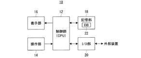
図1に示すように、この実施形態に係るトラップ管理装置10は、CPU(Central Processing Unit)を含む制御部12を有している。そして、この制御部12には、操作手段としての操作部14、表示手段としての表示部16、記憶手段としての記憶部18、および図示しない複数の入出力端子を備えた入出力インタフェース部(以下、I/O部と言う。)20が、接続されている。このようなトラップ管理装置10は、例えばタブレットPC(Personal
Computer)によって実現され、具体的には当該タブレットPCにトラップ管理プログラムがインストールされることによって実現される。
As shown in FIG. 1, the
Specifically, it is realized by installing a trap management program in the tablet PC.
なお、トラップ管理プログラムは、例えば図示しないCD−ROM(Compact Disk Read Only Memory)によって供給される。このため、I/O部20は、上述した入出力端子として、CD−ROMドライブ装置が接続されるUSB(Universal
Serial Bus)端子を備えている。そして、このCD−ROMドライブ装置により読み取られたトラップ管理プログラムは、制御部12による制御によって、記憶部18を構成する図示しないバードディスク装置に記憶され、つまりインストールされる。このインストールの完了後、CD−ROMドライブ装置はUSB端子から取り外される。
The trap management program is supplied by, for example, a CD-ROM (Compact Disk Read Only Memory) (not shown). For this reason, the I /
Serial Bus) terminal. The trap management program read by the CD-ROM drive device is stored in a bird disk device (not shown) constituting the
また、I/O部20は、上述のUSB端子以外にも、例えばRS−232C端子を備えている。そして、このRS−232C端子には、外部装置として、後述するID(RFID;Radio Frequency Identification)読み込み装置およびトラップ検査装置が接続される。ただし、これらID読み取り装置およびトラップ検査装置は、少なくともこのトラップ管理装置10がいわゆる現場(トラップが設置されている場所)に持ち込まれるときにのみ接続されれば、足りる。
Further, the I /
さらに、表示部16は、操作部14としても機能する液晶型タッチスクリーン構成とされている。従って、操作部14には、当該タッチスクリーンを操作(タッチ)するための指示手段としての図示しない入力用ペン(スタイラスペン)が、付属されている。
Further, the
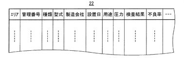
そしてさらに、上述のハードディスク装置(記憶部18)には、蒸気プラントに設置されている全てのトラップに関するデータ、詳しくは個々のトラップの属性を表す属性データが、記憶されている。具体的には、当該ハードディスク装置には、これらの属性データを統合したデータベース22が記憶されており、このデータベース22には、図2に示すように、当該属性データとして、それぞれのトラップ毎の“エリア(設置エリア)”,“管理番号”,“種類(作動原理)”,“型式”,“製造会社”,“設置日”,“用途”,“蒸気圧力”,“検査結果”,“不良率”等を表すデータが、格納されている。
Further, the hard disk device (storage unit 18) described above stores data relating to all traps installed in the steam plant, specifically attribute data representing attributes of individual traps. Specifically, a
これらのうち、“エリア”は、例えば3桁の数値で表され、“管理番号”は、例えば5桁の数値で表される。そして、実際の管理では、これら“エリア”を表す3桁の数値(エリア番号)と“管理番号”を表す5桁の数値との組み合わせによって、個々のトラップが特定(識別)される。また、“検査結果”は、上述したトラップ検査装置による検査結果を指し、当該“検査結果”には、検査が行われた日時も含まれる。なお、この“検査結果”には、複数回分の検査結果が順次記憶され、つまり蓄積される。さらに、“不良率”とは、トラップが不良となる度合(言わば故障発生率)を言い、この“不良率”は、“検査結果”に基づいて判定される。この“不良率”の判定方法については、後で詳しく説明する。また、図には示さないが、トラップには、通常、バイパスバルブ等の補助的部材が付属される。そして、このバイパスバルブを含む各種補助的部材の属性、例えば“管理番号”,“型式”,“製造会社名”,“設置日”,“用途”,“蒸気圧力”,“検査結果”等に関するデータも、それぞれのトラップの属性データとしてデータベース22に記憶されている。
Among these, “area” is represented by a three-digit numerical value, for example, and “management number” is represented by a five-digit numerical value, for example. In actual management, each trap is specified (identified) by a combination of a three-digit numerical value (area number) representing the “area” and a five-digit numerical value representing the “management number”. The “inspection result” indicates an inspection result by the trap inspection apparatus described above, and the “inspection result” includes the date and time when the inspection was performed. In this “inspection result”, the inspection results for a plurality of times are sequentially stored, that is, accumulated. Further, the “failure rate” refers to the degree of failure of the trap (ie, the failure occurrence rate), and this “failure rate” is determined based on the “inspection result”. The method for determining the “defective rate” will be described in detail later. Although not shown in the figure, auxiliary members such as a bypass valve are usually attached to the trap. The attributes of various auxiliary members including the bypass valve, such as “control number”, “model”, “manufacturer name”, “installation date”, “use”, “steam pressure”, “inspection result”, etc. Data is also stored in the
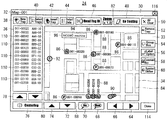
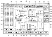
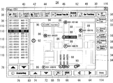
さて、上述のトラップ管理プログラムが起動されると、表示部16の表示画面に、図示しないメイン画面(ウィンドウ)が表示される。このメイン画面には、それぞれのエリアに対応するマップファイルの一覧が表示される。そして、いずれかのマップファイルが選択される(ペン先でタッチされる)と、表示部16の表示画面に、例えば図3に示すようなマップ画面(ダイアログボックス)24が表示される。
When the above-described trap management program is activated, a main screen (window) (not shown) is displayed on the display screen of the
このマップ画面24においては、その上部に、横長のタイトルバー30が表示される。そして、このタイトルバー30内に、当該マップ画面24の見出しである例えば“Map-001”という文字列32が、左詰めで表示される。なお、この“Map-001”という文字列32は、上述のメイン画面において“001”番のエリアが選択されたことを表す。そして、タイトルバー30の下方のクライアント領域33に、当該クライアント領域33の過半を占める矩形のマップ領域34が表示され、このマップ領域34の周りを囲むように、リスト領域36、各種ボタン38〜80、およびフィールド82が表示される。
On the
このうち、マップ領域34には、エリアの見取図、例えば平面図84が、表示される。また、このマップ領域34には、当該エリア内のどこにどのようなトラップが配置されているのかを表すアイコン86,86,…(言わば単独表示子)も、表示される。さらに、これらのアイコン86,86,…の近傍に、それぞれに対応するトラップの識別番号、つまりエリア番号と管理番号とをハイフン(−)で組み合わせた番号を表す文字列88,88,…が、表示される。そしてさらに、これらのアイコン86,86,…とは異なる表示子としてのグループアイコン90(言わばグループ表示子)、および要注意アイコン92も、表示される。また、任意の文字列(コメント)94が記されたコメントボックス96も、表示される。
Among these, in the
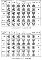
それぞれのアイコン86は、円形の形状をしており、その内部には、アルファベットの文字が、付されている。この文字は、対応するトラップの用途を表し、具体的には、図4に示すように、当該文字が“L”である場合には、対応するトラップが“主管(Drip Line)”用であることを表す。そして、この文字が“P”である場合には、対応するトラップが“諸装置(Process group)”用であることを表し、当該文字が“TC”の場合は、“銅管製トレースライン(Copper
Tracer)”用であることを表す。さらに、“TF”は、“鋼管製トレースライン(Steel Tracer)”用を表し、“TS”は、“ステンレス管製トレースライン(Stainless
steel Tracer)”用を表す。そして、“O”は、“その他(Other group)”を表す。これらの用途(文字)は、上述したデータベース22内の“用途”に基づいて、区分けられる。即ち、データベース22内の“用途”項には、それぞれのトラップ毎に“主管”,“諸装置”,“銅管製トレースライン”,“鋼管製トレースライン”,“ステンレス管製トレースライン”および“その他”のいずれかを表すデータが記憶されている。そして、この“用途”項のデータに基づいて、各アイコン86,86,…に付される文字が決定される。
Each
“TF” means “Steel Tracer” and “TS” means “Stainless Trace Line” (Stainless).
steel tracer) ”and“ O ”represents“ Other group. ”These uses (characters) are classified based on the“ uses ”in the
つまり、この実施形態によれば、各アイコン86,86,…に付された文字から、それぞれに対応するトラップの用途を、直観的かつ同時に把握することができる。この用途は、上述したように個々のトラップの重要度、ひいては個々の配管の重要度と密接に関係するので、かかる用途を直観的かつ同時に把握できるということは、トラップを含む蒸気プラント全体を管理する上で、極めて有効である。
That is, according to this embodiment, it is possible to intuitively and simultaneously grasp the usage of the trap corresponding to each
また、各アイコン86,86,…(円の内側)には、色彩が付されている。そして、この色彩は、対応するトラップの稼働状況を表している。例えば、“正常”であるトラップに対応するアイコン86は、緑色で表される。そして、比較的に小規模な(緊急の対策を要しない程度の)漏れを生じている言わば“漏れ小”の状態にあるトラップは、黄色のアイコン86で表され、それよりも大規模な“漏れ”を生じているトラップは、赤色のアイコン86で表される。さらに、“詰まり”を生じているトラップは、青色のアイコン86で表され、“休止中”の状態にあるトラップは、灰色のアイコン86で表される。また、“未検査”の状態にあるトラップ、詳しくは予定されている検査が未だ実施されていないトラップは、白色で表される。これらの稼働状況(色彩)は、データベース22内の最新の“検査結果”に基づいて、区分けられる。つまり、データベース22内の“検査結果”項には、それぞれのトラップ毎に“正常”,“漏れ小”,“漏れ”,“詰まり”,“休止中”および“未点検”のいずれかを表すデータが、検査日時を表すデータと共に、記憶されている。そして、この検査日時が最新である“検査結果”項のデータに基づいて、各アイコン86,86,…の色彩が決定される。
Each
従って、この実施形態によれば、各アイコン86,86,…の色彩から、それぞれに対応するトラップの稼働状況を、直観的かつ同時に把握することができる。しかも、当該稼動状況として、“正常”および“異常”のみならず、“休止中”および“未検査”という状況をも知ることができる。さらに、“異常”については、“漏れ小”,“漏れ”および“詰まり”という当該“異常”の具体的な種類を認識することができる。このこともまた、蒸気プラントを管理する上で、極めて有効である。
Therefore, according to this embodiment, it is possible to intuitively and simultaneously grasp the operation status of the trap corresponding to each
さらに、各アイコン86,86,…の周縁は、太線で囲まれている。そして、この太線(言わば囲み線)の種類、例えば色によって、上述した不良率が表現される。具体的には、当該囲み線の色が黒(図では実線)である場合は、対応するトラップの不良率が比較的に低い言わば“低不良率”であることを表す。一方、囲み線の色が赤(図では点線)である場合には、対応するトラップの不良率が比較的に高い言わば“高不良率”であることを表す。かかる不良率(囲み線の種類)は、データベース22内の“不良率”に基づいて、区分けられる。つまり、データベース22内の“不良率”項には、それぞれのトラップ毎に“低不良率”および“高不良率”のいずれかを表すデータが、記憶されている。そして、この“不良率”項のデータに基づいて、各アイコン86,86,…の囲み線の種類が決定される。
Further, the periphery of each
つまり、各アイコン86,86,…の囲み線の種類(色)から、それぞれに対応するトラップの不良率を、直観的かつ同時に把握することができる。従って、例えば当該不良率が高い(言わば故障し易い)傾向にある箇所にはより耐久性の高いトラップを採用する等の適切な処置を講ずることができ、より効果的なプラント管理を行うことができる。
That is, from the types (colors) of the surrounding lines of the
一方、グループアイコン90は、複数のトラップの集合体を表す。例えば、複数のトラップが比較的に狭い場所に密集して設けられており、これらのトラップを個別のアイコン86,86,…で表示するのが困難なときに、当該グループアイコン90が用いられる。
On the other hand, the
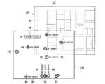
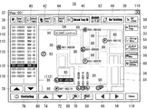
ここで、任意のグループアイコン90がペン先でタッチされるとする。すると、図5に符号98で示すように、タッチされたグループアイコン90の近傍に吹き出しマークが表示される。そして、この吹き出しマーク98内に、機器情報として、上述したのと同様のアイコン86,86,…が、例えば縦1列に表示される。これらのアイコン86,86,…は、グループアイコン90によって代表されるトラップのそれぞれに対応し、当該各アイコン86,86,…に付されている文字、色彩および囲み線の種類は、それぞれに対応するトラップの用途、稼働状況および不良率を表す。また、これらのアイコン86,86,…の近傍には、上述したのと同様の文字列88,88,…、つまり各トラップの識別番号が、表示される。
Here, it is assumed that an
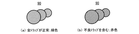
さらに、グループアイコン90自体にも、色彩が付されている。そして、この色彩によって、当該グループアイコン90によって代表される(つまり吹き出しマーク98内のアイコン86,86,…に対応する)トラップが全て“正常”であるか否かが、表現されている。例えば、グループアイコン90によって代表されるトラップが全て“正常”である場合、換言すれば吹き出しマーク98内の全てのアイコン86,86,…が緑色で表されている場合、当該グループアイコン90は、図6(a)に示すように、緑色で表示される。一方、グループアイコン90によって代表されるトラップに“正常”でないもの(言わば非正常のもの)が含まれている場合、換言すれば吹き出しマーク98内のアイコン86,86,…のいずれかが緑色以外の色彩で表されている場合、当該グループアイコン90は、図6(b)に示すように、赤色で表示される。
Further, the
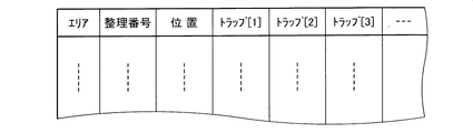
なお、かかるグループアイコン90は、図7に示すようなグループリストによって管理されている。即ち、このグループリストは、トラップ管理プログラムに組み込まれており、当該グループリストには、それぞれのグループアイコン90毎に、“エリア”,“整理番号”,“位置”,“トラップ[n](n=1,2,…)”等のデータが記録される。詳しくは、“エリア”には、それぞれのグループアイコン90が設けられているエリアの番号が記録され、“整理番号”には、当該グループアイコン90に対して個別に付与されたシリアル番号が記録される。そして、“位置”には、それぞれのグループアイコン90のマップ領域34上での座標が記録され、“トラップ[n]”には、当該グループアイコン90によって代表される各トラップの識別番号が記録される。つまり、このグループリストには、それぞれのグループアイコン90の属性データが記録される。なお、図には示さないが、上述した各アイコン88,88,…や、この後に説明する要注意アイコン92,およびコメントボックス96もまた、同様のリストによって管理される。
The
このように、この実施形態によれば、複数台のトラップが密集して設置されている場合、これらのトラップは、1つのグループアイコン90によって代表して表示される。従って、マップ領域34が多数のアイコン86,86,…によって煩雑になるのが防止され、当該マップ領域34が簡潔になり見易くなる。また、このグループアイコン90をタッチするだけで、当該グループアイコン90によってどのようなトラップが代表されているのか(包含されているのか)を知ることができる。このことは、多数のトラップが設置されている蒸気プラントを管理する上で、極めて有効である。
As described above, according to this embodiment, when a plurality of traps are densely installed, these traps are representatively displayed by one
さらに、グループアイコン90の色彩から、当該グループアイコン90によって代表される全てのトラップが“正常”であるのか否かを直観的に把握することができる。つまり、各トラップの稼働状況を言わば予備的に認識することができる。このこともまた、多数のトラップを管理する上で、非常に有用である。
Furthermore, from the color of the
続いて、要注意アイコン92は、次のような意味合いを持つ。即ち、上述したように、各トラップにはバイパスバルブ等の補助的部材が付属されており、この補助的部材の属性データもまたデータベース22に記憶されている。ここで、いずれかの補助的部材に何らかの“異常”が生じている、具体的にはデータベース22内の当該補助的部材に対応する“検査結果”項に“異常”というデータが記憶されている、とする。この場合、当該“異常”の状態にある補助的部材が付属されたトラップが、要注意アイコン92で表示される。つまり、この要注意アイコン92の表示から、これに対応するトラップの補助的部材に“異常”が生じていることを、直観的に把握することができる。
Subsequently, the
また、この要注意アイコン92がペン先でタッチされると、図8に符号100で示すように、当該要注意アイコン92の近傍に概略矩形の付箋マークが表示される。そして、この付箋マーク100内に、“異常”の概要、例えば当該“異常”を生じている補助的部材の識別番号(エリア番号と管理番号との組み合わせ)および“異常”の内容を表す文字列102が、上述の属性データに基づいて表示される。従って、この付箋マーク100の表示から、換言すれば要注意アイコン92をタッチするだけで、補助的部材に生じている“異常”の概要を認識することができる。このことは、例えば当該補助的部材の“異常”が急を要するものであるか否かを判断するのに、非常に有用である。
When the
なお、要注意アイコン92は、例えば図9に示すように、円形の形状をしており、その内部は、黄色で塗りつぶされている。そして、この黄色で塗りつぶされた円内に、赤色の“!”マークが付された態様とされている。また、この要注意アイコン92は、対応するトラップが“正常”であり、かつ当該トラップに付属されている補助的部材が“異常”である場合にのみ、アイコン86に代えて表示される。従って、トラップ自体が“正常”でない場合、つまり“漏れ小”,“漏れ”,“詰まり”,“休止中”および“未点検”のいずれかの状態にある場合は、たとえ補助的部材が“異常”であったとしても、当該トラップ自体の状態に応じた態様(色彩)のアイコン86が、優先的に表示される。
Note that the
そして、コメントボックス96は、マップ領域34上に任意のコメントを付記するためのものであり、例えば図3においては、当該コメントとして“NC&MC machine”という文字列94が付記されている。これは、このコメントボックス96で示される場所に、NC(Numerical
Control)機械およびMC(Machining Center)機械が設置されていることを表す。なお、後述するが、このコメントボックス96内の文字列94の内容(コメント)は、任意に変更することができる。
The
Control) and MC (Machining Center) machine are installed. As will be described later, the contents (comments) of the
これらの平面図84,アイコン86,86,…,文字列88,88,…,グループアイコン90,要注意アイコン92およびコメントボックス96が表示されるマップ領域34は、図10に示すように、2つのレイヤ106および108を有している。そして、これら2つのレイヤ106および108の一方、例えば第1レイヤ106に、平面図84が表示される。この平面図84は、例えばビットマップ(BitMap)形式やGIF(Graphics Interchange Format)形式,或いはJPEG(Joint
Photographic coding Experts Group)形式等の画像データに基づいて表示される。かかる画像データは、例えば図示しない紙面に描画された設計図等をスキャナで読み取ることによって得られる。
These plan views 84,
Displayed based on image data such as Photographic coding Experts Group) format. Such image data is obtained, for example, by reading a design drawing or the like drawn on a paper (not shown) with a scanner.
そして、他方の第2レイヤ108に、平面図84以外の要素、つまりアイコン86,86,…,文字列88,88,…,グループアイコン90,要注意アイコン92およびコメントボックス96(文字列94を含む)が、表示される。また、上述した吹き出しマーク98(アイコン86,86,…および文字列88,88,…を含む)、並びに付箋マーク100(文字列102を含む)も、この第2レイヤ108に表示される。そして、これらの第1レイヤ106および第2レイヤ108が互いに合成されることで、マップ領域34が構成される。
Then, elements other than the
なお、後述するが、第2レイヤ108に表示されている各要素(アイコン86,86,…,グループアイコン90,要注意アイコン92およびコメントボックス96)は、それぞれ個別に任意に削除可能とされている。また、任意の要素を追加したり、或いは任意の要素の配置を変更したりすることもできる。そして、各要素のうちアイコン86が削除,追加または配置変更されたときは、これに付随する文字列88も同時に削除,追加および配置変更される。
As will be described later, each element (
図3に戻って、マップ領域34の左横方に、当該マップ領域34よりも小さい縦長矩形のリスト領域36が表示される。このリスト領域36には、蒸気プラントに設置されているトラップの一覧が表示され、詳しくは各トラップの識別番号および型式を表す文字列110,110,…が縦一列に表示される。従って、これらの文字列110,110,…、つまりリストから、蒸気プラントにどのような(識別番号および型式の)トラップが設置されているのかを、確認することができる。
Returning to FIG. 3, a vertically long
ただし、上述したように蒸気プラントには多数のトラップが設置されているので、これら全てのトラップの情報(識別番号および型式)がリスト領域36に表示されると、例えば目的のトラップを探すに時間が掛かる等の不都合が生じる。このため、この実施形態では、当該リスト領域36に表示されるトラップを制限することができる。
However, since a large number of traps are installed in the steam plant as described above, when information (identification numbers and types) of all these traps is displayed in the
即ち、リスト領域36の上方に表示されている“Select Traps”と記されたボタン40がタッチされると、図示しない選択条件設定画面(ダイアログボックス)が表示される。この選択条件設定画面においては、リスト領域36に表示させるトラップの条件、例えばエリアや設置日等を任意に設定することができる。そして、この条件が設定され、当該選択条件設定画面が閉じられると、設定された条件を満足するトラップのみの情報が、リスト領域36に表示される。
That is, when the
ここで、例えば、リスト領域36内の文字列110,110,…のいずれかがタッチされる、つまり当該リスト領域36内においていずれかのトラップが指示される、とする。すると、図11に示すように、指示されたトラップの文字列(同図において上から5番目の文字列)110が、反転表示される。また、マップ領域34内に当該指示されたトラップに対応するアイコン86が存在する場合は、そのアイコン86に付随する文字列(図11においてマップ領域34の中央付近にある文字列)88も反転表示される。従って、このマップ領域34内で反転表示されている文字列88の位置、厳密には当該文字列88が付随されたアイコン86の位置から、リスト領域36内で指示されたトラップの実際の設置場所を認識することができる。
Here, for example, it is assumed that any of the character strings 110, 110,... In the
これとは反対に、マップ領域34内において任意のトラップが指示された、つまり当該マップ領域34内の任意のアイコン86がタッチされた、とする。この場合、タッチされたアイコン86に付随する文字列88が反転表示される。これと同時に、当該指示されたトラップを表す文字列110がリスト領域36内に存在する場合には、その文字列110も反転表示される。
On the contrary, it is assumed that an arbitrary trap is instructed in the
なお、上述のリスト領域36内で指示されたトラップが任意のグループアイコン90により代表されるものである場合は、図12に示すように、当該グループアイコン90用の吹き出しマーク98が表示されると共に、この吹き出しマーク98内の対応する文字列(図12において一番下にある文字列)88が、反転表示される。これとは反対に、吹き出しマーク98内の任意のアイコン86がタッチされた場合には、当該タッチされたアイコン86に付随する文字列88が反転表示される。そして、タッチされたアイコン86に対応する文字列110がリスト領域36内に存在する場合には、その文字列110も反転表示される。
If the trap indicated in the
さらに、これらの如く任意のトラップが指示されている状態、例えば図11に示す状態において、マップ領域34の上方にある“Detail Data”と記されたボタン44がタッチされると、マップ画面24上に、図13に示すような属性情報表示画面(ダイアログボックス)26が表示される。この属性情報表示画面26においては、その上部に、横長のタイトルバー200が表示される。そして、このタイトルバー200内には、当該属性情報表示画面26の見出しである例えば“Detail
Data”という文字列202が、左詰めで表示される。さらに、このタイトルバー200の下方のクライアント領域204に、現在指示されているトラップの属性を表す属性情報が表示される。
Further, in a state where an arbitrary trap is instructed as described above, for example, in the state shown in FIG. 11, when the
A
具体的には、クライアント領域204の下部に、“Basic”,“Setting”,“Operation”および“Others”と記された4つのタブ206〜212が表示される。このうちの例えば“Basic”と記されたタブ206がタッチされると、図13に示すように“エリア(Area)”,“管理番号(Trap
No.)”,“種類(Trap Type)”,“型式(Model)”,“製造会社名(Manufacturer)”等の言わば基本的な情報が表示される。そして、“Setting”と記されたタブ208がタッチされると、図には示さないが、“設置日”や“用途”,“蒸気圧力”等の言わば設置条件に関する情報が表示される。さらに、“Operation”と記されたタブ210がタッチされると、“検査結果”や“不良率”等の稼働状況に係る情報が表示される。そして、“Others”というタブ212がタッチされると、上述した補助的部材に関する情報等が表示される。従って、この属性情報表示画面26を表示させることで、それぞれのトラップの具体的な属性情報を認識することができる。
Specifically, four
Basic information such as “No.)”, “Trap Type”, “Model”, “Manufacturer Name”, etc. is displayed, and a tab labeled “Setting” When the user touches 208, although not shown in the drawing, information on installation conditions such as “installation date”, “use”, “steam pressure”, etc. is displayed, and a
なお、この属性情報表示画面26に表示される属性情報は、言うまでもなくデータベース22に記憶されている属性データに基づいて表示される。また、この属性情報表示画面26は、いわゆるダブルクリック操作によっても表示させることができる。即ち、マップ領域34において任意のアイコン86がダブルクリック(連続して2回タッチ)されると、当該属性情報表示画面26が表示される。このことは、グループアイコン90によって代表されるトラップについても同様である。つまり、グループアイコン90によって代表されるいずれかのトラップが指示されている状態で“Detail Data”ボタン44がタッチされた場合、或いは当該トラップに対応する(吹き出しマーク98内の)アイコン86がタッチされた場合も、そのトラップに関する属性情報表示画面26が表示される。そして、この属性情報表示画面26のタイトルバー200の右端にある“閉じる(×印)”ボタン214がタッチされると、当該属性情報表示画面26は閉じられる。
Needless to say, the attribute information displayed on the attribute
また、例えば図11に示す状態において、リスト領域36の下方にある上向きの矢印ボタン78がタッチされると、当該リスト領域36内の指示対象(反転表示位置)が上方に向けて1つずつ移動する。つまり、現在指示されているトラップに代えて、その1つ上方に表示されているトラップが新たな指示対象となる。そして、この指示対象の変更に伴い、マップ領域34においても、当該新たに指示対象とされたトラップに対応する文字列88(吹き出しマーク98内のものを含む)が存在する場合には、その文字列88が反転表示される。一方、下向きの矢印ボタン80がタッチされると、リスト領域36内の指示対象が下方に向けて1つずつ移動すると共に、マップ領域34内に対応する文字列88が存在する場合にはその文字列88が反転表示される。
For example, in the state shown in FIG. 11, when the
さらに、リスト領域36の上方であって上述した“Select Traps”ボタン40の左横方(クライアント領域33の左上隅)にある“New Trap”ボタン38がタッチされると、図示しないトラップ新規登録画面(ダイアログボックス)が表示される。このトラップ新規登録画面は、手動(キーボード操作等)により新規のトラップを登録するための画面である。即ち、このトラップ新規登録画面においてトラップの属性データが手動入力されると、入力された属性データはデータベース22に記憶され、つまり登録される。そして、登録されたトラップの属性が上述の選択条件設定画面で設定された条件を満足する場合には、そのトラップの情報(識別番号および型式)がトラップ領域36に追加される。
Further, when a “New Trap”
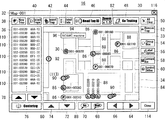
また、図14に示すように、リスト領域36において任意のトラップ(文字列110)が指示されている状態で、“Select Traps”ボタン40の右横方にある“Insert Trap”ボタン42がタッチされ、さらに同図に符号112で示すようにマップ領域34内の任意の位置(図14において左下側の位置)がタッチされる、とする。すると、図15に示すように、当該マップ領域34内のタッチされた位置112に、現在指示されているトラップに対応するアイコン86が追加される。勿論、この追加されたアイコン86の態様(文字,色彩および囲み線)は、対応するトラップの属性(“用途”,“稼働状況”および“不良率”)に従う。そして、追加されたアイコン86の近傍(右横方)には、上述と同様の文字列88(識別番号)が表示され、厳密には反転表示される。
Further, as shown in FIG. 14, the “Insert Trap”
なお、後で詳しく説明するが、上述のタッチ位置112としてグループアイコン90がタッチされた場合は、このグループアイコン90内にトラップが追加される。つまり、上述した吹き出しマーク98内に、当該トラップに対応するアイコン86および文字列88が追加される。
As will be described in detail later, when the
また、かかるアイコン86の追加は、いわゆるドラッグ・アンド・ドロップ操作によっても実現することができる。即ち、リスト領域36内の任意のトラップ(文字列110)がマップ領域34内の任意の位置にドラッグ・アンド・ドロップされると、その位置(ドロップされた位置)に、対応するアイコン86および文字列88が追加される。また、グループアイコン90上にドラッグ・アンド・ドロップされた場合には、当該グループアイコン90(吹き出しマーク98)内に、対応するアイコン86および文字列88が追加される。
The addition of the
そして、クライアント領域33の右上隅にある“All Clear”と記されたボタン50がタッチされると、上述した第2レイヤ108(図10参照)上の全ての要素、つまりアイコン86,86,…,文字列88,88,…,グループアイコン90,要注意アイコン92およびコメントボックス96が、一括消去される。なお、図には示さないが、当該“All
Clear”ボタン50がタッチされた後、実際に消去を行っても良いか否かをオペレータに確認するための確認画面が、表示される。そして、この確認画面上で所定の操作が成される、例えば“OK”ボタンがタッチされることを条件に、当該消去が実行される。
When the
After the “Clear”
さらに、“All Clear”ボタン50の下方にある“Remove Trap”ボタン52がタッチされると、その時点で指示されているアイコン86およびこれに付随する文字列88のみが、マップ領域34から消去される。なお、グループアイコン90,要注意アイコン92およびコメントボックス96についても、これと同様の要領で任意に消去することができる。さらに、グループアイコン90(吹き出しマーク95)内の個々のアイコン86および文字列88についても、同様の要領で消去できる。そして、この“Remove
Trap”ボタン52による消去時においても、“All Clear”ボタン50による消去時と同様の確認画面が表示される。
Furthermore, when the “Remove Trap”
Even when erasing with the “Trap”
そしてさらに、“Remove Trap”ボタン52の下方にある“Group Box”ボタン54は、グループアイコン90を新規に作成するためのものである。即ち、この“Group
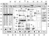
Box”ボタン54がタッチされた後、例えば図16に符号113で示すようにマップ領域34内の任意の位置(図16において左側かつやや下寄りの位置)がタッチされる、とする。すると、図17に示すように、当該マップ領域34内のタッチされた位置113に、新たなグループアイコン90が作成される。なお、この新たなグループアイコン90は、デフォルト状態として緑色(図6参照)、つまり非正常なトラップを含まない態様で表示される。
Furthermore, a “Group Box”
Assume that after the “Box”
そして、この新たなグループアイコン90が作成された後は、上述した要領で、当該グループアイコン90にトラップ(アイコン86および文字列88)が追加される。即ち、リスト領域36において任意のトラップ(文字列110)が指示されている状態で、“Insert Trap”ボタン42がタッチされた後、この新たなグループアイコン90がタッチされると、図18に示すように、当該グループアイコン90にトラップが追加される。つまり、グループアイコン90の近傍に吹き出しマーク98が表示されると共に、当該吹き出しマーク98内に、対応するアイコン86および文字列88が追加される。このことは、上述したようにリスト領域36からグループアイコン90に向けてドラッグ・アンド・ドロップ操作が成された場合も、同様である。なお、吹き出しマーク98のサイズは、これに表示されるアイコン88および文字列88(トラップ)の数に応じて、自動的に調整される。
After the
続いて、“Group Box”ボタン54の下方にある“Label Option”ボタン56は、アイコン86に付随する文字列88の表示態様を変更するためのものである。即ち、いずれかのアイコン86が指示されている状態で、この“Label
Option”ボタン56がタッチされると、図示しないラベルオプション画面が表示される。このラベルオプション画面においては、アイコン86に対する文字列88の位置を任意に設定することができ、詳しくは当該アイコン86の上方,下方,右横方および左横方のいずれに文字列88を配置するのかを選択することができる。また、文字列88の並び方向、つまり縦書きおよび横書きのいずれかを任意に選択することもできる。さらに、文字列88を非表示とすることもできる。
Subsequently, the “Label Option”
When the “Option”
さらに、“Label Option”ボタン56の下方にある“Comment Box”ボタン58は、上述したコメントボックス94を新規に作成するためのものである。即ち、この“Comment
Box”ボタン58がタッチされた後、マップ領域34内の任意の位置がタッチされると、その位置に、デフォルト状態(文字列104が未入力)のコメントボックス94が表示される。そして、このコメントボックス94内に、任意の文字列(コメント)104が手動入力される。なお、入力される文字列104の長さ(文字数)に応じて、コメントボックス94のサイズが自動的に設定される。また、文字列104が入力された後も、例えばコメントボックス94をダブルクリックすることによって、当該文字列104の内容を変更することができる。
Further, a “Comment Box”
When an arbitrary position in the
そして、マップ領域34内の任意のアイコン86が、当該マップ領域34内の別の位置にドラッグ・アンド・ドロップされると、その位置に、当該任意のアイコン36が移動する。そして、このアイコン36に付随する文字列88も一緒に移動する。なお、グループアイコン90,要注意アイコン92およびコメントボックス96についても、同様の要領で移動させることができる。また、アイコン86の移動先がグループアイコン90上である場合には、当該アイコン86は文字列88と共にグループアイコン90(吹き出しマーク98)内に追加される。
When an
そしてさらに、“Comment Box”ボタン58の下方にある“Symbol Define”ボタン60がタッチされると、マップ画面24上に、図19に示すような不良率判定基準定義画面(ダイアログボックス)28が表示される。この不良率判定基準定義画面28は、上述した“不良率”を判定する際の判定基準を定義するための画面である。
Further, when the “Symbol Define”
即ち、この不良率判定基準定義画面28においては、その上部に、横長のタイトルバー300が表示され、このタイトルバー300内には、当該不良率判定基準定義画面28の見出しである例えば“Symbol Definition”という文字列302が、左詰めで表示される。そして、このタイトルバー300の下方のクライアント領域304に、3つのフィールド306,308および310が表示される。このうち、フィールド306には、異常の種類X、具体的には“All
failure(全ての異常)”,“Leak(漏れ小を除く漏れ)”,“Blocked(詰まり)”および“Fail Pipe or Valve(その他の異常)”という4つの文字列312,312,…が、縦一列に表示される。そして、このフィールド306の下方には、これら4つの文字列312,312,…のいずれかを選択するための上下2つの矢印ボタン314および316が表示される。この矢印ボタン314および316の操作によって選択された文字列312は、反転表示される。そして、フィールド308には、異常の発生回数Yを表す任意の数値(1以上の整数)が入力される。この数値は、当該フィールド308を間に挟んでその上下にある2つの矢印ボタン318および320によって変更可能とされている。さらに、フィールド310には、当該異常発生回数Yのカウント対象期間(年数)Zを表す任意の数値(1以上の整数)が入力される。この数値もまた、当該フィールド310の上下にある2つの矢印ボタン322および324によって任意に変更可能とされている。
That is, on the defect rate determination
Four
これらのフィールド306,308および310内のX,YおよびZは、“X occurs less than Y times in Z years.”という一連の文章を表す文字列326を構成する。そして、この文字列326の上方には、当該文字列326の題目である“Low
rate Failure”という文字列328が表示される。つまり、これらの文字列326および328によって、“過去Z年間における異常Xの発生回数がYよりも少ないトラップは低不良率であると判定する。”という当該“低不良率”の判定基準が定義される。なお、図19は、“過去5年間における全ての異常の発生回数がいずれも3回未満であるトラップは低不良率であると判定する。”と定義されている状態を示す。また、文字列328の左横方には、“低不良率”のシンボルマーク(アイコン86を模擬したもの)330が表示される。
X, Y, and Z in these
A
そして、上述の文字列326(矢印ボタン314および316)の下方には、“高不良率”のシンボルマーク332と、“High rate Failure”という文字列334とが、横並びで表示される。さらに、これらシンボルマーク332および文字列334の下方に、3つの矩形枠336,338および340が表示され、これらの矩形枠336,338および340内には、上述のフィールド306,308および310内と同じ情報X,YおよびZが表示される。そして、これらの矩形枠336,338および340内に表示された情報X,YおよびZは、“X
occurs Y times or more in Z years.”という一連の文章を表す文字列342を構成する。つまり、文字列334および342によって、“過去Z年間における異常Xの発生回数がY以上であるトラップは高不良率であると判定する。”という当該“高不良率”の判定基準が定義される。
Below the character string 326 (
The
さらに、文字列342の下方には、“OK”ボタン344と“Cancel”ボタン346とが横並びで表示されており、このうちの“OK”ボタン344がタッチされると、その時点で定義されている判定基準が確定され、その後、不良率判定基準定義画面28が閉じられる。そして、確定された判定基準に基づいて、それぞれのトラップが“低不良率”および“高不良率”のいずれに属するのかが判定し直され、その判定結果に基づいて、データベース22内の“不良率”項が更新される。そしてさらに、この更新された“不良率”項に基づいて、各アイコン86,86,…(囲み線)が表示し直される。
Furthermore, below the
一方、不良率判定基準定義画面28の“Cancel”ボタン346がタッチされた場合は、判定基準は据え置かれる。そして、不良率判定基準定義画面28が閉じられ、当該不良率判定基準定義画面28が表示される前(“Symbol
Define”ボタン60がタッチされる前)の状態に戻る。タイトルバー300の右端にある“閉じる”ボタン348がタッチされた場合も、この“Cancel”ボタン346がタッチされた場合と同様である。
On the other hand, when the “Cancel”
When the “Close” button 348 at the right end of the
再び図3に戻って、マップ領域34の下方にある“ズームイン”ボタン70および“ズームアウト”ボタン68のいずれかがタッチされると、マップ領域34内の表示倍率が変更される。具体的には、0.5倍,1.0倍,1.5倍,2.0倍,3.0倍および5.0倍の範囲内で、当該表示倍率が変更される。そして、現在の倍率が、マップ領域34の上方にあるフィールド82に表示される。なお、表示倍率が変わると、当然に各アイコン86,86,…,グループアイコン90,要注意アイコン92およびコメントボックス96間の相対的な位置関係(間隔)が変わるが、個々のアイコン86,グループアイコン90,要注意アイコン92およびコメントボックス96自体のサイズは、変わらない。また、文字列88,88,…,吹き出しマーク98および付箋マーク100自体のサイズも、変わらない。
Returning to FIG. 3 again, when either the “zoom-in”
そして、“ズームイン”ボタン70および“ズームアウト”ボタン68と横並びで配置されている上下左右の各矢印ボタン64,66,72および74は、上述したマップ領域34の表示倍率が1.0倍よりも大きいとき、換言すれば当該マップ領域34にエリア全体が表示されていないときに、このマップ領域34に表示させるエリアの場所を移動(スライド)させるためのものである。即ち、マップ領域34にエリア全体が表示されていないときは、これらの矢印ボタン64,66,72および74を操作することで、当該マップ領域34内にエリアの希望場所を表示させることができる。
The up, down, left, and
そしてさらに、上述の如く表示倍率が1.0倍よりも大きいときに、クライアント領域33(マップ画面24)の左下隅にある“Centering”ボタン76がタッチされると、エリアの中心がマップ領域34の中心に合わせられる。このいわゆるセンタリング処理は、例えばエリアのどの部分がマップ領域34に表示されているのかが判らなくなったとき等に、便利である。
Further, when the “Centering”
また、マップ領域34の上方にある“Read Tag ID”と記されたボタン46がタッチされると、図示しないID読み込み画面(ダイアログボックス)が表示される。このID読み込み画面は、上述のID読み込み装置から任意のトラップの属性データを取り込むときに、用いられる。
When a
即ち、個々のトラップには、図示しない個別のIDタグが取り付けられており、このIDタグには、それが取り付けられているトラップの属性データが予め記録されている。このIDタグに記録された属性データは、トラップ管理装置10に接続された状態にあるID読み込み装置によって読み込まれ、読み込まれた属性データは、当該ID読み込み装置からトラップ管理装置10に転送される。そして、トラップ管理装置10に転送された属性データは、データベース22に記憶されている各トラップの属性データと照合される。
That is, an individual ID tag (not shown) is attached to each trap, and attribute data of the trap to which the ID tag is attached is recorded in advance. The attribute data recorded in the ID tag is read by an ID reading device connected to the
ここで、IDタグから読み込まれた属性データが未登録のトラップのものである場合、その属性データはデータベース22に新規に記憶される。つまり、トラップの新規登録が自動的に行われる。そして、新規登録されたトラップは、検査対象として設定される。一方、IDタグから読み込まれた属性データが登録済みのトラップのデータである場合には、そのトラップは、直ちに検査対象として設定される。そして、このように検査対象とされたトラップを表す文字列110がリスト領域36内に存在する場合には、当該文字列110が反転表示される。また、マップ領域34内に当該検査対象とされたトラップに対応するアイコン86(グループアイコン90(吹き出しマーク98)内のものを含む)が存在する場合には、そのアイコン86に付随する文字列88も反転表示される。
If the attribute data read from the ID tag is for an unregistered trap, the attribute data is newly stored in the
このようにして検査対象となるトラップが設定された後、上述のID読み込み画面は自動的に閉じられる。そして、これに続いて、マップ領域34の上方にある“Go Testing”と記されたボタン48がタッチされると、トラップ管理装置10は、検査待ちの状態(モード)になる。なお、この検査待ちの状態においては、トラップ管理装置10に上述のトラップ検査装置が接続されていることが、前提とされる。
After the trap to be inspected is set in this way, the above-described ID reading screen is automatically closed. Subsequently, when the
即ち、トラップ検査装置によって任意のトラップ、厳密には現在検査対象とされているトラップの検査が行われると、その検査結果を表すデータが、トラップ検査装置からトラップ管理装置10に転送される。そして、このトラップ管理装置10に転送されたデータは、現在検査対象とされているトラップの“検査結果”データとして、データベース20に記憶される。さらに、この新たな“検査結果”に基づいて、上述した“不良率”が判定し直され、言わばデータベース22の内容が更新される。そして、マップ領域34内に検査対象トラップに対応するアイコン86が存在する場合には、そのアイコン86が改めて表示し直される。また、当該アイコン86がグループアイコン90(吹き出しマーク98)に含まれるものである場合には、そのアイコン86と共に当該グループアイコン90も表示し直される。
That is, when an arbitrary trap, specifically, a trap that is currently inspected, is inspected by the trap inspection apparatus, data representing the inspection result is transferred from the trap inspection apparatus to the
さらに、クライアント領域33の右下にある“Close”ボタン114がタッチされると、マップ画面24の表示が終了されて、上述したメイン画面に戻る。また、タイトルバー30の右端にある“閉じる”ボタン116がタッチされた場合も、同様である。
Further, when the “Close”
なお、新規にマップファイルを作成するには、次の手順による。即ち、まず、任意の画像データを用意し、その画像データをトラップ管理プログラムによる所定の手順で読み出すことによって、平面図84のみの新規のマップファイルを作成する。そして、例えば実際の設計図等を参照しながら、当該平面図84上に、上述した要領で適宜アイコン86,86,…,グループアイコン90およびコメントボックス96を追加すればよい。
To create a new map file, follow the procedure below. That is, first, arbitrary image data is prepared, and the image data is read by a predetermined procedure by the trap management program, thereby creating a new map file of only the
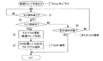
ところで、新規のグループアイコン90が作成されるとき(図16および図17参照)、つまり上述した“Group Box”ボタン54がタッチされると、制御部12(CPU)は、図20のフローチャートで示される新規グループ作成タスクを実行する。
By the way, when a
即ち、制御部12は、まず、ステップS1に進み、上述の“Group Box”ボタン54のタッチ操作の後に改めてもう1度タッチ操作が成されたか否かを判断する。そして、改めてタッチ操作が成されたと判断すると、ステップS3に進み、当該タッチ操作が成されたのがマップ領域34内であるか否かを判断する。ここで、マップ領域34内でタッチされたと判断すると、制御部12は、ステップS5に進み、上述したグループリスト(図7参照)を更新し、詳しくは当該グループリストに新規のグループを作成する。そして、ステップS7に進み、タッチされた位置(例えば図16および図17における位置113)にデフォルト状態(緑色)のグループアイコン90を追加し、この図20で示される一連の新規グループ作成タスクを終了する。
That is, the
一方、ステップS3においてマップ領域34以外の位置がタッチされた場合、制御部12は、ステップS9に進む。そして、このステップS9において、タッチされたのが別の操作対象であるか否か、つまりリスト領域36,各ボタン38〜90,114および116のいずれかがタッチされたか否かを判断する。ここで、いずれかの操作対象(リスト領域36,各ボタン38〜90,114および116のいずれか)がタッチされた場合、制御部12は、タッチされた操作対象に従う処理を実行するべく、この新規グループ作成タスクを終了する。それ以外の位置、つまりクライアント領域33の残りの部分(言わば間隙部分)またはタイトルバー30がタッチされた場合は、制御部12は、ステップS9からステップS1に戻る。
On the other hand, when a position other than the
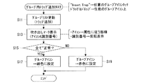
続いて、任意のグループアイコン90に任意のトラップが追加されるとき(図18参照)、つまり任意のトラップ(文字列110)が指示されている状態で、“Insert Trap”ボタン42がタッチされ、さらに任意のグループアイコン90がタッチされたとき、或いは任意のグループアイコン90上に任意のトラップ(文字列110またはアイコン86)がドラッグ・アンド・ドロップされたとき、制御部12は、図21のフローチャートで示されるグループ内トラップ追加タスクを実行する。
Subsequently, when an arbitrary trap is added to the arbitrary group icon 90 (see FIG. 18), that is, in the state where an arbitrary trap (character string 110) is instructed, the “Insert Trap”
即ち、制御部12は、まず、ステップS11において、グループリストを更新し、詳しくはトラップの追加先となるグループアイコン90用の“トラップ[n]”項に、追加対象となるトラップの識別番号を追加する。そして、ステップS13に進み、当該トラップの追加先となるグループアイコン90の近傍に吹き出しマーク98を表示させると共に、この吹き出しマーク98内に今回追加されたトラップに対応するアイコン86およびその識別番号を表す文字列88を追加する。このとき、アイコン86については、追加されたトラップの属性(用途,稼働状況および不良率)に従う態様(文字,色彩および囲み線)で表示させ、文字列88については、反転表示させる。
That is, first, in step S11, the
そして、制御部12は、ステップS15に進み、今回のトラップの追加先であるグループアイコン90によって代表されるトラップが全て“正常”であるか否かを判断する。ここで、当該全てのトラップが“正常”であるとき、制御部12は、ステップS17に進む。そして、このステップS17において、グループアイコン90の色彩を緑色(図6参照)に設定した後、この図21で示される一連のグループ内トラップ追加タスクを終了する。一方、“正常”でないトラップが含まれるときは、制御部12は、ステップS15からステップS19に進む。そして、このステップS19において、グループアイコン90の色彩を赤色に設定して、このグループ内アイコン追加タスクを終了する。
Then, the
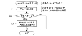
さらに、任意のグループアイコン90がタッチされたとき(図5参照)、制御部12は、図22のフローチャートで示されるグループ内トラップ表示タスクを実行する。
Further, when an
即ち、制御部12は、ステップS21において、グループリストを参照し、詳しくはタッチされたグループアイコン90に対応するグループに1以上のトラップが含まれているか否か、より詳しくは当該グループアイコン90用の“トラップ[n]”項に1以上のトラップの識別番号が記録されているか否かを、確認する。そして、ステップS23において、当該グループに1以上のトラップが含まれていると判断すると、ステップS25に進み、タッチされたグループアイコン90の近傍に吹き出しマーク98を表示させると共に、この吹き出しマーク98内に当該グループアイコン90により代表される全てのトラップに対応するアイコン86およびその識別番号を表す文字列88を表示させる。このステップS25の実行後、制御部12は、図22で示される一連のグループ内トラップ表示タスクを終了する。一方、ステップS23においてトラップが含まれていないと判断した場合は、そのままこのグループ内トラップ表示タスクを終了する。
That is, in step S21, the
そして、上述したリスト領域36内で任意のトラップ(文字列110)が指示されたとき(図12参照)、制御部12は、図23で示される対応グループ検索タスクを実行する。
When an arbitrary trap (character string 110) is designated in the
即ち、制御部12は、まず、ステップS31において、グループリストを参照し、詳しくは指示されたトラップがいずれかのグループに含まれているか否かを確認する。そして、ステップS33において、当該指示されたトラップがいずれかのグループに含まれていると判断すると、ステップS35に進み、そのグループに対応するグループアイコン90が現在マップ領域34内に表示されているか否かを判断する。この判断は、グループリスト内の“位置”データ(座標)に基づいて行われる。
That is, first, in step S31, the
このステップS35において、目的のグループアイコン90がマップ領域34内に表示されていると判断すると、制御部12は、ステップS37に進み、当該グループアイコン90の近傍に吹き出しマーク98を表示させると共に、この吹き出しマーク98内に当該グループアイコン90により代表される全てのトラップに対応するアイコン86,86,…およびその識別番号を表す文字列88,88,…を表示させる。そして、当該文字列88,88,…のうち、現在指示されているトラップに対応するものについては、反転表示させる。かかるステップS37の実行後、制御部12は、この図23で示される一連の対応グループ検索タスクを終了する。
If it is determined in step S35 that the
なお、ステップS33において、いずれのグループにも指示されたトラップが含まれていないと判断した場合は、制御部12は、そのままこの対応グループ検索タスクを終了する。また、ステップS35において、当該指示されたトラップを含むグループアイコン90がマップ領域34内に表示されていないと判断した場合も、同様に、この対応グループ検索タスクを終了する。
If it is determined in step S33 that none of the groups includes the specified trap, the
以上のように、この実施形態によれば、複数台のトラップが密集して設置されている場合には、これらのトラップは、1つのグループアイコン90によって代表して表示される。従って、マップ領域34が多数のアイコン86,86,…によって煩雑になるのが防止され、当該マップ領域34が簡潔になり見易くなる。
As described above, according to this embodiment, when a plurality of traps are densely installed, these traps are representatively displayed by one
また、グループアイコン90をタッチすると、吹き出しマーク98が表示されると共に、この吹き出しマーク98内に、当該グループアイコン90によって代表されるトラップのアイコン86,86,…と識別番号を表す文字列98,98,…とが表示される。つまり、グループアイコン90をタッチするだけで、当該グループアイコン90によってどのようなトラップが代表されているのかを知ることができる。
When the
さらに、グループアイコン90の色彩から、当該グループアイコン90によって代表されるトラップが全て“正常”であるか否かを直観的に把握することができる。つまり、各トラップの大まかな稼働状況を認識することができる。
Furthermore, it is possible to intuitively grasp from the color of the
なお、この実施形態においては、互いに密集して配置されているという関係にある複数台のトラップを、1つのグループアイコン90により代表して表示することとしたが、これに限らない。例えば、互いに共通の配管に取り付けられている、或いは互いの用途が同じである、さらにはメンテナンス者が共通する等の、互いに所定の関係にある複数台のトラップを当該グループアイコン90により代表させてもよい。
In this embodiment, a plurality of traps that are closely arranged with each other are represented by a
また、グループアイコン90がタッチされたときに吹き出しマーク98が表示され、この吹き出しマーク98内に、当該グループアイコン90によって代表されるトラップのアイコン86,86,…および文字列98,98,…が表示されるようにしたが、これに限らない。例えば、マップ領域34内の所定場所、若しくはマップ領域34以外の或る場所に、当該アイコン86,86,…および文字列98,98,…を表示させるための欄を設けてもよい。
Further, when the
さらに、グループアイコン90の色彩によって、当該グループアイコン90により代表される全てのトラップが“正常”であるか否かを表現することとしたが、これに限らない。例えば、グループアイコン90の形状、或いは模様等の、色彩以外の態様によって、同内容を表現してもよい。
Further, although the color of the
また、グループアイコン90により代表される全てのトラップが“正常”であるか否かではなく、例えば“漏れ”や“詰まり”等の緊急の対策を要するトラップが含まれるか否か、或いは重要度の高いトラップが含まれているか否かに応じて、当該グループアイコン90の色彩(態様)を変えてもよい。勿論、これ以外の条件を満足するか否かに応じて、グループアイコン90の色彩を変えてもよい。
In addition, whether or not all traps represented by the
そして、この実施形態においては、スチームトラップを管理するためのトラップ管理装置10を例に挙げて説明したが、これに限らない。例えば、エアトラップやガストラップ等のスチームトラップ以外のトラップを管理するための装置に、この発明を適用してもよい。また、回転機や圧力容器等のトラップ以外の機器を管理する装置にも、この発明を適用できることは、言うまでもない。
In this embodiment, the
また、上述のトラップ管理プログラムは、CD−ROMによって供給されることとしたが、これに限らない。例えば、FD(Flexible Disc)やDVD(Digital Versatile Disc)等の他の記憶媒体によって供給されてもよいし、インターネット等の電気通信回線を通じて供給されてもよい。 Moreover, although the above-described trap management program is supplied by a CD-ROM, the present invention is not limited to this. For example, it may be supplied by other storage media such as FD (Flexible Disc) and DVD (Digital Versatile Disc), or may be supplied through an electric communication line such as the Internet.
さらに、平面図84については、ビットマップ形式やGIF形式,JPEG形式等の画像データに基づいて表示されることとしたが、これに限らない。例えば、CAD(Computer Aided Design)やCAM(Computer Aided Manufacturing)等のデータに基づいて表示されてもよいし、画面上で任意に描画されるものであってもよい。また、平面図84に限らず、配管図や鳥瞰図等を見取図として表示してもよい。
Further, the
そしてさらに、トラップ管理装置10を実現するためのハードウェア構成として、タブレットPCを採用したが、これに限らない。例えば、ノートブック型PCやパームトップ・コンピュータを採用してもよい。また、デスクトップ型PCを採用してもよいが、携帯性を考慮すると、言うまでもなくタブレットPCが有利である。さらに、これらの汎用型コンピュータではなく、トラップ管理プログラムが組み込まれたトラップ管理装置10専用の装置を構成してもよい。
Furthermore, although the tablet PC is adopted as a hardware configuration for realizing the
なお、この実施形態で説明した内容、例えば図2に示すデータベース22や、図3等に示す画面構成、或いは図20等に示すフローチャート等は、飽くまでこの発明を実現するための一例であって、これ以外の形態により本発明を実現してもよい。
The contents described in this embodiment, for example, the
10 トラップ管理装置
12 制御部
14 操作部
16 表示部
18 記憶部
22 データベース
24 マップ画面
34 マップ領域
84 平面図
86 アイコン
88 文字列(識別番号)
90 グループアイコン
92 要注意アイコン
96 コメントボックス
98 吹き出しマーク
DESCRIPTION OF
90
Claims (6)
表示画面を有する表示手段と、
前記表示画面に前記設備の見取図を表示させる第1表示制御手段と、
前記複数の機器のうち互いに所定の関係にある2以上の機器を1つの表示子により代表して前記見取図上に表示させる第2表示制御手段と、
を具備することを特徴とする、設備管理装置。 In equipment management devices that manage multiple devices that make up equipment,
Display means having a display screen;
First display control means for displaying a sketch of the equipment on the display screen;
A second display control means for displaying two or more devices having a predetermined relationship among the plurality of devices on the floor plan by representing one display element;
An equipment management apparatus comprising:
前記指示手段によって指示された前記表示子により代表される前記2以上の機器の内容を表す機器情報を前記表示画面に表示させる第3表示制御手段と、
をさらに備える、請求項1に記載の設備管理装置。 Instruction means for indicating any of the indicators;
Third display control means for displaying device information representing the contents of the two or more devices represented by the indicator indicated by the instruction means on the display screen;
The facility management apparatus according to claim 1, further comprising:
前記設備を構成する複数の機器のうち互いに所定の関係にある2以上の機器を1つの表示子により代表して前記見取図上に表示させる第2表示制御手順と、
をコンピュータに実行させるための設備管理プログラム。 A first display control procedure for displaying a facility sketch on the display screen of the display means;
A second display control procedure for displaying two or more devices in a predetermined relationship among a plurality of devices constituting the facility on the sketch drawing by representing one display element;
Management program to make a computer execute.
Priority Applications (1)
| Application Number | Priority Date | Filing Date | Title |
|---|---|---|---|
| JP2004290007A JP4603328B2 (en) | 2004-10-01 | 2004-10-01 | Equipment management device and equipment management program |
Applications Claiming Priority (1)
| Application Number | Priority Date | Filing Date | Title |
|---|---|---|---|
| JP2004290007A JP4603328B2 (en) | 2004-10-01 | 2004-10-01 | Equipment management device and equipment management program |
Publications (2)
| Publication Number | Publication Date |
|---|---|
| JP2006106936A true JP2006106936A (en) | 2006-04-20 |
| JP4603328B2 JP4603328B2 (en) | 2010-12-22 |
Family
ID=36376634
Family Applications (1)
| Application Number | Title | Priority Date | Filing Date |
|---|---|---|---|
| JP2004290007A Expired - Lifetime JP4603328B2 (en) | 2004-10-01 | 2004-10-01 | Equipment management device and equipment management program |
Country Status (1)
| Country | Link |
|---|---|
| JP (1) | JP4603328B2 (en) |
Cited By (10)
| Publication number | Priority date | Publication date | Assignee | Title |
|---|---|---|---|---|
| JP2009169863A (en) * | 2008-01-18 | 2009-07-30 | Internatl Business Mach Corp <Ibm> | Computer system, method and computer program for managing components |
| JP2009245202A (en) * | 2008-03-31 | 2009-10-22 | Hitachi Ltd | Monitoring control screen creating device |
| JP2013114471A (en) * | 2011-11-29 | 2013-06-10 | Yokogawa Electric Corp | Wireless field monitoring and display apparatus |
| US8639798B2 (en) | 2008-01-21 | 2014-01-28 | International Business Machines Corporation | Managing configuration items |
| JP2016018395A (en) * | 2014-07-08 | 2016-02-01 | 三菱電機株式会社 | Device management apparatus, device management method, and display device |
| EP3147738A1 (en) * | 2015-09-25 | 2017-03-29 | Yokogawa Electric Corporation | Inspection work support device, inspection work support system, and inspection work support method |
| JP2019074827A (en) * | 2017-10-13 | 2019-05-16 | 富士通株式会社 | Display program, display device and display method |
| JP2021012544A (en) * | 2019-07-05 | 2021-02-04 | オムロン株式会社 | Monitoring device, monitoring method, monitoring program, and recording medium |
| JP2022161499A (en) * | 2021-04-09 | 2022-10-21 | セイコーエプソン株式会社 | Molding machine management system |
| JP2025020396A (en) * | 2019-01-22 | 2025-02-12 | 能美防災株式会社 | Disaster prevention support system |
Citations (4)
| Publication number | Priority date | Publication date | Assignee | Title |
|---|---|---|---|---|
| JPH03215889A (en) * | 1990-01-19 | 1991-09-20 | Yamatake Honeywell Co Ltd | Facility controller |
| JPH1139030A (en) * | 1997-07-15 | 1999-02-12 | Tlv Co Ltd | Equipment management device and computer-readable recording medium recording equipment management program |
| JP2000315105A (en) * | 1999-04-30 | 2000-11-14 | Star Micronics Co Ltd | NC machine tool management system and management program |
| JP2000347725A (en) * | 1999-06-04 | 2000-12-15 | Hitachi Ltd | Plant operation monitoring device |
-
2004
- 2004-10-01 JP JP2004290007A patent/JP4603328B2/en not_active Expired - Lifetime
Patent Citations (4)
| Publication number | Priority date | Publication date | Assignee | Title |
|---|---|---|---|---|
| JPH03215889A (en) * | 1990-01-19 | 1991-09-20 | Yamatake Honeywell Co Ltd | Facility controller |
| JPH1139030A (en) * | 1997-07-15 | 1999-02-12 | Tlv Co Ltd | Equipment management device and computer-readable recording medium recording equipment management program |
| JP2000315105A (en) * | 1999-04-30 | 2000-11-14 | Star Micronics Co Ltd | NC machine tool management system and management program |
| JP2000347725A (en) * | 1999-06-04 | 2000-12-15 | Hitachi Ltd | Plant operation monitoring device |
Cited By (13)
| Publication number | Priority date | Publication date | Assignee | Title |
|---|---|---|---|---|
| JP2009169863A (en) * | 2008-01-18 | 2009-07-30 | Internatl Business Mach Corp <Ibm> | Computer system, method and computer program for managing components |
| US8639798B2 (en) | 2008-01-21 | 2014-01-28 | International Business Machines Corporation | Managing configuration items |
| JP2009245202A (en) * | 2008-03-31 | 2009-10-22 | Hitachi Ltd | Monitoring control screen creating device |
| JP2013114471A (en) * | 2011-11-29 | 2013-06-10 | Yokogawa Electric Corp | Wireless field monitoring and display apparatus |
| JP2016018395A (en) * | 2014-07-08 | 2016-02-01 | 三菱電機株式会社 | Device management apparatus, device management method, and display device |
| US10254748B2 (en) | 2015-09-25 | 2019-04-09 | Yokogawa Electric Corporation | Inspection work support device, inspection work support system, and inspection work support method |
| EP3147738A1 (en) * | 2015-09-25 | 2017-03-29 | Yokogawa Electric Corporation | Inspection work support device, inspection work support system, and inspection work support method |
| JP2019074827A (en) * | 2017-10-13 | 2019-05-16 | 富士通株式会社 | Display program, display device and display method |
| JP2025020396A (en) * | 2019-01-22 | 2025-02-12 | 能美防災株式会社 | Disaster prevention support system |
| JP7789878B2 (en) | 2019-01-22 | 2025-12-22 | 能美防災株式会社 | Disaster prevention support system |
| JP2021012544A (en) * | 2019-07-05 | 2021-02-04 | オムロン株式会社 | Monitoring device, monitoring method, monitoring program, and recording medium |
| JP7334511B2 (en) | 2019-07-05 | 2023-08-29 | オムロン株式会社 | MONITORING DEVICE, MONITORING METHOD, MONITORING PROGRAM, AND RECORDING MEDIUM |
| JP2022161499A (en) * | 2021-04-09 | 2022-10-21 | セイコーエプソン株式会社 | Molding machine management system |
Also Published As
| Publication number | Publication date |
|---|---|
| JP4603328B2 (en) | 2010-12-22 |
Similar Documents
| Publication | Publication Date | Title |
|---|---|---|
| JP5715786B2 (en) | Dynamically linked graphical messaging system, dynamically linked graphical message and method | |
| JPH1139030A (en) | Equipment management device and computer-readable recording medium recording equipment management program | |
| CN105144011B (en) | Graphical process variable trend monitoring for process control systems | |
| US20080320409A1 (en) | Tightly-Coupled Synchronized Selection, Filtering, and Sorting Between Log Tables and Log Charts | |
| US20150205398A1 (en) | Graphical drawing object management methods and apparatus | |
| CN105051635B (en) | Navigation within a graphical depiction of a process control plant | |
| JP4603328B2 (en) | Equipment management device and equipment management program | |
| CN103680654B (en) | For control method and system for nuclear power plant master-control room | |
| US9910643B2 (en) | Program for program editing | |
| JP2006059236A (en) | Facility management apparatus and facility management program | |
| CN104820871B (en) | TPS trading volumes predict the method for visualizing and system with threshold range prediction | |
| JP3847585B2 (en) | Editor registration device, registration program, and recording medium recording the same | |
| JP5444166B2 (en) | Equipment management device, screen display method, and program | |
| JPH0619669A (en) | Image data editing operation method | |
| JP2001266171A (en) | Plotting device and computer-readable recording medium with plotting program recorded thereon | |
| JPH096982A (en) | Hierarchy diagram editing device | |
| JP4433648B2 (en) | Multipoint measurement data display device, multipoint measurement data display method, and multipoint measurement data display program | |
| KR20130093334A (en) | Automatic implementation method and apparatus of workflows in computer programming using user interface | |
| JP3882403B2 (en) | Personnel change management device and program storage medium thereof | |
| JP4892509B2 (en) | Monitoring screen creation device | |
| JP6476080B2 (en) | Design support apparatus, design support method, design support program, and recording medium | |
| JP2014123260A (en) | Image creation device of system monitoring screen | |
| JP5039312B2 (en) | Program, method and apparatus for controlling multiple pointers | |
| CN115639935B (en) | Table operation method and device and readable storage medium | |
| CN102428430A (en) | Supervisory control system, method and computer program product for control technology systems |
Legal Events
| Date | Code | Title | Description |
|---|---|---|---|
| A621 | Written request for application examination |
Free format text: JAPANESE INTERMEDIATE CODE: A621 Effective date: 20070816 |
|
| A977 | Report on retrieval |
Free format text: JAPANESE INTERMEDIATE CODE: A971007 Effective date: 20091120 |
|
| A131 | Notification of reasons for refusal |
Free format text: JAPANESE INTERMEDIATE CODE: A131 Effective date: 20091201 |
|
| A521 | Request for written amendment filed |
Free format text: JAPANESE INTERMEDIATE CODE: A523 Effective date: 20100201 |
|
| TRDD | Decision of grant or rejection written | ||
| A01 | Written decision to grant a patent or to grant a registration (utility model) |
Free format text: JAPANESE INTERMEDIATE CODE: A01 Effective date: 20100928 |
|
| A01 | Written decision to grant a patent or to grant a registration (utility model) |
Free format text: JAPANESE INTERMEDIATE CODE: A01 |
|
| A61 | First payment of annual fees (during grant procedure) |
Free format text: JAPANESE INTERMEDIATE CODE: A61 Effective date: 20101001 |
|
| FPAY | Renewal fee payment (event date is renewal date of database) |
Free format text: PAYMENT UNTIL: 20131008 Year of fee payment: 3 |
|
| R150 | Certificate of patent or registration of utility model |
Ref document number: 4603328 Country of ref document: JP Free format text: JAPANESE INTERMEDIATE CODE: R150 |
|
| R250 | Receipt of annual fees |
Free format text: JAPANESE INTERMEDIATE CODE: R250 |
|
| R250 | Receipt of annual fees |
Free format text: JAPANESE INTERMEDIATE CODE: R250 |
|
| EXPY | Cancellation because of completion of term |