JP2006106959A - 非真円工作物研削用データ作成方法及び非真円工作物研削盤 - Google Patents
非真円工作物研削用データ作成方法及び非真円工作物研削盤 Download PDFInfo
- Publication number
- JP2006106959A JP2006106959A JP2004290281A JP2004290281A JP2006106959A JP 2006106959 A JP2006106959 A JP 2006106959A JP 2004290281 A JP2004290281 A JP 2004290281A JP 2004290281 A JP2004290281 A JP 2004290281A JP 2006106959 A JP2006106959 A JP 2006106959A
- Authority
- JP
- Japan
- Prior art keywords
- grinding
- cam
- curve
- recess
- circular workpiece
- Prior art date
- Legal status (The legal status is an assumption and is not a legal conclusion. Google has not performed a legal analysis and makes no representation as to the accuracy of the status listed.)
- Granted
Links
Images



Landscapes
- Grinding And Polishing Of Tertiary Curved Surfaces And Surfaces With Complex Shapes (AREA)
- Numerical Control (AREA)
Abstract
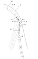
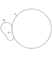
【解決手段】 カム50の凹部Aを2点(ポイントP2−ポイントP12)で特定し、特定した2点で凹部Aに砥石半径に対応する円弧Rを設ける。これにより大径の砥石車28でカム50の凹部Aを粗研削できるデータを作成可能なため、研削効率が上がるとともに、砥石車の寿命を延ばすことが可能になる。また、該円弧Rとカム50のオフセットが与えられた外周面K2’とを曲線L3,L4で滑らかに繋いであるので、小径の砥石車で仕上げ研削する際にも砥石車を滑らかに送ることができ、所望のカム50形状に仕上げることが可能である。
【選択図】 図7
Description
本発明は、
非真円工作物の外周面に仕上げ研削用のオフセットを与えるステップと、
非真円工作物の凹部を2点で特定するステップと;
特定した2点で凹部に砥石半径に対応する円弧を設けるステップと;
設けた円弧と、非真円工作物の前記オフセットが与えられた外周面とを滑らかに繋ぐ曲線を設けるステップとからなることを技術的特徴とする。
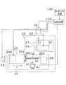
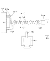
図1は、本発明の第1実施形態に係る研削盤20を示している。研削盤20はベッド22を有し、ベッド22上には、工作物テーブル23がZ軸方向(トラバース軸)に移動可能に設置され、この工作物テーブル23は、サーボモータ24および該サーボモータ24により回転される送りねじ(図示せず)によってZ軸方向に移動される。本実施形態では、2台の研削盤にて粗研削、仕上げ研削をするものとするが、砥石径が異なるのみで同じ機械構成を取るので、研削盤20は、粗研削を行う分のみを説明する。
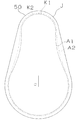
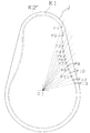
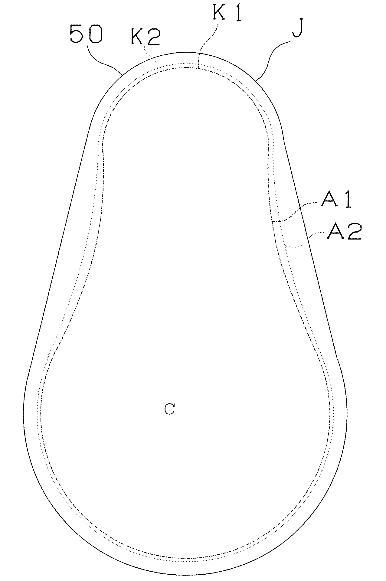
数値制御装置100は、先ず、リフトデータを入力し(S12)、オフセットを設定する(S14)。ここで言うオフセットとは、図4中に示す実線(外周面)K2’のように、最終カム形状K1に上述した仕上げ研削用の研削盤で研削するための取りしろ含んだ形状を意味する。ここで、リフトデータは、上述したように中心Cからのカム角度と、バルブのリフト量(即ち、中心Cからの距離)を定めた連続する点を意味し、図中でポイントP1〜P13として模式的に表す。なお、リフトデータは、本来的には最終カム形状K1を規定する点であるが、図4中では以降の説明の便宜上、オフセットされた実線K2’上に描いてある。
25 主軸台
27 砥石台
28 サーボモータ
29 砥石車
40 定寸装置
50 カム
52 カムシャフト
100 数値制御装置
C 軸心
R 円弧
L3、L4 曲線
Claims (4)
- 外周面に凹部を有する非真円工作物を研削するための非真円工作物研削用データ作成方法であって:
非真円工作物の外周面に仕上げ研削用のオフセットを与えるステップと、
非真円工作物の凹部を2点で特定するステップと;
特定した2点で凹部に砥石半径に対応する円弧を設けるステップと;
設けた円弧と、非真円工作物の前記オフセットが与えられた外周面とを滑らかに繋ぐ曲線を設けるステップとからなることを特徴とする非真円工作物研削用データ作成方法。 - 前記滑らかに繋ぐ曲線を設けるステップでは、前記凹部を特定する2点からそれぞれ、反対側に所定の区間を設け、区間内に前記曲線を規定するための複数の点を取り、それぞれの点で、上記円弧の接線角度と等しくなるようにすることを特徴とする請求項1の非真円工作物研削用データ作成方法。
- 前記決定した曲線がS字状になるかを判断し、S字状になる場合には、前記所定区間を広げて再度曲線を規定する複数の点を求めることを特徴とする請求項2の非真円工作物研削用データ作成方法。
- 請求項1〜請求項3のいずれか1の非真円工作物研削用データ作成方法により非真円工作物研削用の形状データを求めることを特徴とする非真円工作物研削盤。
Priority Applications (1)
| Application Number | Priority Date | Filing Date | Title |
|---|---|---|---|
| JP2004290281A JP4371033B2 (ja) | 2004-10-01 | 2004-10-01 | 非真円工作物研削用データ作成方法及び非真円工作物研削盤 |
Applications Claiming Priority (1)
| Application Number | Priority Date | Filing Date | Title |
|---|---|---|---|
| JP2004290281A JP4371033B2 (ja) | 2004-10-01 | 2004-10-01 | 非真円工作物研削用データ作成方法及び非真円工作物研削盤 |
Publications (2)
| Publication Number | Publication Date |
|---|---|
| JP2006106959A true JP2006106959A (ja) | 2006-04-20 |
| JP4371033B2 JP4371033B2 (ja) | 2009-11-25 |
Family
ID=36376655
Family Applications (1)
| Application Number | Title | Priority Date | Filing Date |
|---|---|---|---|
| JP2004290281A Expired - Fee Related JP4371033B2 (ja) | 2004-10-01 | 2004-10-01 | 非真円工作物研削用データ作成方法及び非真円工作物研削盤 |
Country Status (1)
| Country | Link |
|---|---|
| JP (1) | JP4371033B2 (ja) |
Cited By (1)
| Publication number | Priority date | Publication date | Assignee | Title |
|---|---|---|---|---|
| CN118466403A (zh) * | 2024-05-13 | 2024-08-09 | 苏州市凌臣采集计算机有限公司 | 带有弦弧补正功能的免编程电子凸轮曲线生成方法及系统 |
-
2004
- 2004-10-01 JP JP2004290281A patent/JP4371033B2/ja not_active Expired - Fee Related
Cited By (1)
| Publication number | Priority date | Publication date | Assignee | Title |
|---|---|---|---|---|
| CN118466403A (zh) * | 2024-05-13 | 2024-08-09 | 苏州市凌臣采集计算机有限公司 | 带有弦弧补正功能的免编程电子凸轮曲线生成方法及系统 |
Also Published As
| Publication number | Publication date |
|---|---|
| JP4371033B2 (ja) | 2009-11-25 |
Similar Documents
| Publication | Publication Date | Title |
|---|---|---|
| IL196380A (en) | Method of grinding an indexable insert and grinding wheel for carrying out the grinding method | |
| JPH10502878A (ja) | 凹状側面を備えたカムを研削する方法及び装置 | |
| JP5181703B2 (ja) | 凹型フレネルレンズ形状部材の加工方法及び凹型フレネルレンズ形状部材 | |
| JP5192268B2 (ja) | カムシャフトの研削加工装置及び研削加工方法 | |
| EP1839809B1 (en) | Grinding method and grinding machine | |
| KR100659433B1 (ko) | 비구면 가공 방법, 비구면 형성 방법 및 비구면 가공 장치 | |
| JP2009184066A5 (ja) | ||
| US20120201623A1 (en) | Method and apparatus for non-rotary machining | |
| JP2010017769A (ja) | 薄板形状ワーク加工方法 | |
| JP2010029947A (ja) | 複合エンドミル及び複合エンドミルを用いた加工方法 | |
| JP7016568B1 (ja) | フレネルレンズ金型製造方法、加工装置および切削工具 | |
| JP2003011014A (ja) | カッターヘッド、曲面加工方法、v溝加工方法、光学部品及び光学部品用金型 | |
| Chen et al. | Design and fabrication of double-circular-arc torus milling cutter | |
| US20100111632A1 (en) | Method and apparatus for non-rotary machining | |
| JP4371033B2 (ja) | 非真円工作物研削用データ作成方法及び非真円工作物研削盤 | |
| JP2000246636A (ja) | グラインディングウォームのシェーピング方法、シェーピング工具及びシェーピング装置 | |
| KR100837726B1 (ko) | 연삭 가공 방법 및 수치 제어 연삭기 | |
| JP4576255B2 (ja) | 工具砥石の形状創成方法 | |
| JP5538754B2 (ja) | センタレス研削用調整車の製造方法、調整車、円錐ころの製作方法 | |
| CN105636744A (zh) | 修整方法和修整设备 | |
| JPH11300501A (ja) | 光学部品の切削加工方法および切削工具 | |
| JP2002001634A (ja) | ブレードの研削方法および研削装置 | |
| JP2007320008A (ja) | カム研削盤及びカム研削方法 | |
| JP2005028556A (ja) | 自由曲面加工方法 | |
| JP5262437B2 (ja) | 砥石のツルーイング方法および研削加工方法 |
Legal Events
| Date | Code | Title | Description |
|---|---|---|---|
| A711 | Notification of change in applicant |
Free format text: JAPANESE INTERMEDIATE CODE: A712 Effective date: 20060410 |
|
| A621 | Written request for application examination |
Free format text: JAPANESE INTERMEDIATE CODE: A621 Effective date: 20070924 |
|
| TRDD | Decision of grant or rejection written | ||
| A01 | Written decision to grant a patent or to grant a registration (utility model) |
Free format text: JAPANESE INTERMEDIATE CODE: A01 Effective date: 20090811 |
|
| A01 | Written decision to grant a patent or to grant a registration (utility model) |
Free format text: JAPANESE INTERMEDIATE CODE: A01 |
|
| A977 | Report on retrieval |
Free format text: JAPANESE INTERMEDIATE CODE: A971007 Effective date: 20090813 |
|
| A61 | First payment of annual fees (during grant procedure) |
Free format text: JAPANESE INTERMEDIATE CODE: A61 Effective date: 20090824 |
|
| FPAY | Renewal fee payment (event date is renewal date of database) |
Free format text: PAYMENT UNTIL: 20120911 Year of fee payment: 3 |
|
| R150 | Certificate of patent or registration of utility model |
Ref document number: 4371033 Country of ref document: JP Free format text: JAPANESE INTERMEDIATE CODE: R150 Free format text: JAPANESE INTERMEDIATE CODE: R150 |
|
| FPAY | Renewal fee payment (event date is renewal date of database) |
Free format text: PAYMENT UNTIL: 20130911 Year of fee payment: 4 |
|
| LAPS | Cancellation because of no payment of annual fees |