JP2006123710A - Foaming filler - Google Patents
Foaming filler Download PDFInfo
- Publication number
- JP2006123710A JP2006123710A JP2004314425A JP2004314425A JP2006123710A JP 2006123710 A JP2006123710 A JP 2006123710A JP 2004314425 A JP2004314425 A JP 2004314425A JP 2004314425 A JP2004314425 A JP 2004314425A JP 2006123710 A JP2006123710 A JP 2006123710A
- Authority
- JP
- Japan
- Prior art keywords
- locking
- locked
- foaming
- foam
- portions
- Prior art date
- Legal status (The legal status is an assumption and is not a legal conclusion. Google has not performed a legal analysis and makes no representation as to the accuracy of the status listed.)
- Granted
Links
- 239000000945 filler Substances 0.000 title claims abstract description 77
- 238000005187 foaming Methods 0.000 title claims abstract description 51
- 239000006260 foam Substances 0.000 claims abstract description 89
- 230000005489 elastic deformation Effects 0.000 claims abstract description 9
- 238000010438 heat treatment Methods 0.000 claims abstract description 8
- 230000003014 reinforcing effect Effects 0.000 abstract description 28
- 238000009413 insulation Methods 0.000 abstract description 2
- 230000008602 contraction Effects 0.000 description 6
- 239000000463 material Substances 0.000 description 6
- 239000006261 foam material Substances 0.000 description 5
- 230000002159 abnormal effect Effects 0.000 description 4
- 229920003002 synthetic resin Polymers 0.000 description 4
- 239000000057 synthetic resin Substances 0.000 description 4
- 239000011248 coating agent Substances 0.000 description 3
- 238000000576 coating method Methods 0.000 description 3
- 230000000694 effects Effects 0.000 description 3
- 239000004088 foaming agent Substances 0.000 description 3
- 238000000465 moulding Methods 0.000 description 3
- 230000002787 reinforcement Effects 0.000 description 3
- 238000003466 welding Methods 0.000 description 3
- VTYYLEPIZMXCLO-UHFFFAOYSA-L Calcium carbonate Chemical compound [Ca+2].[O-]C([O-])=O VTYYLEPIZMXCLO-UHFFFAOYSA-L 0.000 description 2
- VYPSYNLAJGMNEJ-UHFFFAOYSA-N Silicium dioxide Chemical compound O=[Si]=O VYPSYNLAJGMNEJ-UHFFFAOYSA-N 0.000 description 2
- TZCXTZWJZNENPQ-UHFFFAOYSA-L barium sulfate Chemical compound [Ba+2].[O-]S([O-])(=O)=O TZCXTZWJZNENPQ-UHFFFAOYSA-L 0.000 description 2
- 239000003431 cross linking reagent Substances 0.000 description 2
- 229920005989 resin Polymers 0.000 description 2
- 239000011347 resin Substances 0.000 description 2
- 229920005992 thermoplastic resin Polymers 0.000 description 2
- 229920001187 thermosetting polymer Polymers 0.000 description 2
- UOYIYWCAYFTQLH-UHFFFAOYSA-N 3,7-dinitro-1,3,5,7-tetrazabicyclo[3.3.1]nonane Chemical compound C1N2CN([N+](=O)[O-])CN1CN([N+]([O-])=O)C2 UOYIYWCAYFTQLH-UHFFFAOYSA-N 0.000 description 1
- 239000004925 Acrylic resin Substances 0.000 description 1
- 229920000178 Acrylic resin Polymers 0.000 description 1
- 239000004156 Azodicarbonamide Substances 0.000 description 1
- VGGSQFUCUMXWEO-UHFFFAOYSA-N Ethene Chemical compound C=C VGGSQFUCUMXWEO-UHFFFAOYSA-N 0.000 description 1
- 239000005977 Ethylene Substances 0.000 description 1
- MGJKQDOBUOMPEZ-UHFFFAOYSA-N N,N'-dimethylurea Chemical compound CNC(=O)NC MGJKQDOBUOMPEZ-UHFFFAOYSA-N 0.000 description 1
- 229910000831 Steel Inorganic materials 0.000 description 1
- 238000010521 absorption reaction Methods 0.000 description 1
- 239000000853 adhesive Substances 0.000 description 1
- 230000001070 adhesive effect Effects 0.000 description 1
- XOZUGNYVDXMRKW-AATRIKPKSA-N azodicarbonamide Chemical compound NC(=O)\N=N\C(N)=O XOZUGNYVDXMRKW-AATRIKPKSA-N 0.000 description 1
- 235000019399 azodicarbonamide Nutrition 0.000 description 1
- MTAZNLWOLGHBHU-UHFFFAOYSA-N butadiene-styrene rubber Chemical compound C=CC=C.C=CC1=CC=CC=C1 MTAZNLWOLGHBHU-UHFFFAOYSA-N 0.000 description 1
- 210000001217 buttock Anatomy 0.000 description 1
- 229910000019 calcium carbonate Inorganic materials 0.000 description 1
- 238000006243 chemical reaction Methods 0.000 description 1
- 229920001577 copolymer Polymers 0.000 description 1
- 238000004132 cross linking Methods 0.000 description 1
- 238000000354 decomposition reaction Methods 0.000 description 1
- QGBSISYHAICWAH-UHFFFAOYSA-N dicyandiamide Chemical compound NC(N)=NC#N QGBSISYHAICWAH-UHFFFAOYSA-N 0.000 description 1
- 238000001035 drying Methods 0.000 description 1
- 239000013013 elastic material Substances 0.000 description 1
- 229920001971 elastomer Polymers 0.000 description 1
- 238000004070 electrodeposition Methods 0.000 description 1
- 239000003822 epoxy resin Substances 0.000 description 1
- HQQADJVZYDDRJT-UHFFFAOYSA-N ethene;prop-1-ene Chemical group C=C.CC=C HQQADJVZYDDRJT-UHFFFAOYSA-N 0.000 description 1
- 238000001746 injection moulding Methods 0.000 description 1
- 238000005304 joining Methods 0.000 description 1
- 238000004519 manufacturing process Methods 0.000 description 1
- 238000000034 method Methods 0.000 description 1
- AJCDFVKYMIUXCR-UHFFFAOYSA-N oxobarium;oxo(oxoferriooxy)iron Chemical compound [Ba]=O.O=[Fe]O[Fe]=O.O=[Fe]O[Fe]=O.O=[Fe]O[Fe]=O.O=[Fe]O[Fe]=O.O=[Fe]O[Fe]=O.O=[Fe]O[Fe]=O AJCDFVKYMIUXCR-UHFFFAOYSA-N 0.000 description 1
- 239000005011 phenolic resin Substances 0.000 description 1
- 229920000647 polyepoxide Polymers 0.000 description 1
- 229920000098 polyolefin Polymers 0.000 description 1
- 239000000377 silicon dioxide Substances 0.000 description 1
- 239000010959 steel Substances 0.000 description 1
- 229920006132 styrene block copolymer Polymers 0.000 description 1
- 229920002803 thermoplastic polyurethane Polymers 0.000 description 1
- 239000011800 void material Substances 0.000 description 1
- 229910000859 α-Fe Inorganic materials 0.000 description 1
Images


Landscapes
- Body Structure For Vehicles (AREA)
Abstract
Description
本発明は、例えば車両ピラー等に代表される中空構造部材における内部の空隙に発泡体を充填する発泡充填具に関するものである。 The present invention relates to a foam filler that fills a void in an interior of a hollow structural member represented by, for example, a vehicle pillar.
従来、車両ピラー等に代表される中空構造部材は、車両の走行に伴って、中空構造部材における内部の空隙に空気が流通することによって異音が発生したり、中空構造部材の振動によって異音が発生したりすることがあった。こうした異音の発生を抑制するために、中空構造部材の空隙に発泡体を充填することが提案されている。すなわち、その発泡体によって、空隙を遮断するとともに、中空構造部材の振動を低減することにより、中空構造部材における異音の発生は抑制される。 Conventionally, a hollow structural member typified by a vehicle pillar or the like generates an abnormal noise due to air flowing through an internal space in the hollow structural member as the vehicle travels, or an abnormal noise due to vibration of the hollow structural member. May occur. In order to suppress the occurrence of such abnormal noise, it has been proposed to fill the voids of the hollow structural member with a foam. That is, the foam blocks the voids and reduces the vibration of the hollow structural member, thereby suppressing the generation of abnormal noise in the hollow structural member.
中空構造部材の空隙に発泡体を充填するには、発泡充填具が使用される。この種の発泡充填具としては、外部加熱により発泡する発泡部材と、同発泡部材を中空構造部材に固定する係止クリップとを備えたものが提案されている(例えば、特許文献1参照)。特許文献1の発泡充填具は、係止クリップの形状及び弾性を利用して中空構造部材に係止することによって、中空構造部材の内部に固定される。 A foam filler is used to fill the voids of the hollow structural member with the foam. As this type of foam filler, a device including a foam member that foams by external heating and a locking clip that fixes the foam member to a hollow structural member has been proposed (for example, see Patent Document 1). The foam filler of Patent Document 1 is fixed inside the hollow structural member by locking the hollow structural member using the shape and elasticity of the locking clip.
一方、この種の発泡充填具としては、発泡部材と、その発泡部材に設けられる弾性変形部とを備えたものが提案されている(例えば、特許文献2参照)。特許文献2の発泡充填具は、例えば車両ピラーに適用される。この車両ピラーは、インナパネル及びアウタパネルから構成され、各パネルをスポット溶接等によって一体化することで、中空状に形成される。こうした車両ピラーの空隙に特許文献2の発泡充填具を固定するには、アウタパネルと一体化する前のインナパネルに発泡充填具を載置した後、発泡充填具を押さえ付けるようにして、インナパネルにアウタパネルを組み合わせる。このとき、弾性変形部がインナパネル及びアウタパネルによって圧着されることによって、発泡充填具は車両ピラーの内部に固定される。
特許文献1の発泡充填具における係止クリップは、弾性変形して中空構造部材に係止する形状に形成する必要がある。そのため、係止クリップの形状、すなわち発泡充填具の形状について複雑化を招くことになる。一方、特許文献2の発泡充填具には、パネルとの係止部分が存在しないため、こうした発泡充填具において、パネルに対する位置決めは係止部分を利用して行うことができない。従って、発泡充填具の位置決め作業は、発泡充填具をパネルの所定箇所に載置することによって行われるため、こうした作業は手間を要することになる。すなわち、中空構造部材に発泡充填具を容易に装着することが困難であるという問題があった。 The locking clip in the foam filler of Patent Document 1 needs to be formed into a shape that is elastically deformed and locked to the hollow structural member. Therefore, the shape of the locking clip, that is, the shape of the foam filler is complicated. On the other hand, since the foam filler of Patent Document 2 does not have a locking portion with the panel, in such a foam filler, positioning with respect to the panel cannot be performed using the locking portion. Therefore, since the positioning operation of the foam filler is performed by placing the foam filler at a predetermined position on the panel, such an operation requires labor. That is, there is a problem that it is difficult to easily attach the foam filler to the hollow structural member.
この発明は、こうした従来の実情に鑑みてなされたものであり、その目的は、簡易な形状とすることができるとともに、容易に装着することができる発泡充填具を提供することにある。 The present invention has been made in view of such conventional circumstances, and an object of the present invention is to provide a foam filler that can be easily shaped and can be easily attached.
上記の目的を達成するために請求項1に記載の発明は、外部加熱により発泡する発泡部を備え、中空構造部材の内部に固定される発泡充填具において、前記発泡部は弾性変形可能であるとともに、前記発泡部には中空構造部材の内部に係止する少なくとも2つの係止部が設けられ、前記少なくとも2つの係止部の間隔が前記発泡部の弾性変形により変化されることで、前記各係止部が前記中空構造部材に設けられる少なくとも2つの被係止部に係止されることを要旨とする。 In order to achieve the above object, the invention according to claim 1 is provided with a foaming part that foams by external heating, and the foaming part is elastically deformable in a foaming filler fixed inside a hollow structural member. In addition, the foamed portion is provided with at least two locking portions that are locked inside the hollow structural member, and an interval between the at least two locking portions is changed by elastic deformation of the foamed portion. The gist is that each locking portion is locked to at least two locked portions provided in the hollow structural member.
上記の目的を達成するために請求項2に記載の発明は、外部加熱により発泡する発泡部を備え、中空構造部材の内部に固定される発泡充填具において、前記発泡部は弾性変形可能であるとともに、前記発泡部には前記中空構造部材に係止する係止部が設けられ、前記係止部は、前記中空構造部材に設けられる第1の被係止部に係止される第1の係止部と、前記中空構造部材に設けられる第2の被係止部に係止される第2の係止部と、を備え、前記第1の係止部及び第2の係止部を、前記第1の被係止部及び第2の被係止部の間隔と異なる間隔で配設したことを要旨とする。 In order to achieve the above object, the invention according to claim 2 is provided with a foaming portion that foams by external heating, and the foaming portion is elastically deformable in the foaming filler fixed inside the hollow structural member. In addition, the foaming portion is provided with a locking portion that is locked to the hollow structural member, and the locking portion is locked to a first locked portion provided in the hollow structural member. A locking portion; and a second locking portion locked to a second locked portion provided in the hollow structure member, wherein the first locking portion and the second locking portion are provided. The gist is that the first locked portion and the second locked portion are arranged at intervals different from those of the first locked portion.
請求項1及び請求項2の構成によれば、各係止部は、発泡部を弾性変形させることによって、各被係止部に係止される。そのため、各被係止部に係止した各係止部には、発泡部材の弾性力が作用し、その弾性力によって各係止部間には張力が発生する。すなわち、各係止部の係止は、各係止部の形状や弾性力のみに依存することなく、発泡部の弾性力に基づく張力を利用して行うことができるようになる。また一方、発泡充填具を装着する際には、各係止部と各被係止部との関係によって、中空構造部材に対する発泡充填具の位置決めを行うことができる。 According to the structure of Claim 1 and Claim 2, each latching | locking part is latched by each to-be-latched part by elastically deforming a foaming part. Therefore, the elastic force of the foam member acts on each locking portion locked to each locked portion, and tension is generated between the locking portions by the elastic force. That is, the locking of each locking part can be performed using the tension based on the elastic force of the foaming part without depending only on the shape and elastic force of each locking part. On the other hand, when the foam filler is mounted, the foam filler can be positioned with respect to the hollow structure member depending on the relationship between each locking portion and each locked portion.
請求項3に記載の発明は、請求項2に記載の発明において、前記第1の係止部及び第2の係止部の間隔を、前記第1の被係止部及び第2の被係止部の間隔よりも広く設定したことを要旨とする。 According to a third aspect of the present invention, in the second aspect of the present invention, an interval between the first locking portion and the second locking portion is set so that the first locked portion and the second locked portion are separated. The gist is that it is set wider than the interval between the stoppers.
請求項4に記載の発明は、請求項2に記載の発明において、前記第1の係止部及び第2の係止部の間隔を、前記第1の被係止部及び第2の被係止部の間隔よりも狭く設定したことを要旨とする。 According to a fourth aspect of the present invention, in the second aspect of the present invention, the distance between the first locking portion and the second locking portion is the same as the first locked portion and the second locked portion. The gist is that it is set narrower than the interval between the stop portions.
請求項3及び請求項4の構成によれば、各係止部が各被係止部に係止された状態において、各係止部間に張力を有効に作用させることができる。
請求項5に記載の発明は、請求項1から請求項4のいずれか一項に記載の発明において、前記発泡部に伸縮可能な伸縮部を設けたことを要旨とする。
According to the structure of Claim 3 and Claim 4, in the state which each latching | locking part latched by each to-be-latched part, tension | tensile_strength can be made to act effectively between each latching | locking part.
The gist of the invention according to claim 5 is that, in the invention according to any one of claims 1 to 4, a stretchable portion that can be stretched is provided in the foamed portion.
この構成によれば、伸縮部の伸縮を利用して各係止部を各被係止部に容易に係止させることができる。 According to this structure, each latching | locking part can be easily latched to each to-be-latched part using the expansion-contraction of an expansion-contraction part.
本発明によれば、簡易な形状とすることができるとともに、容易に装着することができる。 According to the present invention, it can be a simple shape and can be easily mounted.
以下、本発明を車両のピラーに適用する発泡充填具に具体化した実施形態を図1及び図2に基づいて詳細に説明する。
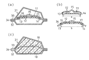
図1に示すように、中空構造部材としてのピラー31は、インナパネル32、アウタパネル33、及び補強部材34を備えている。この補強部材34は、インナパネル32及びアウタパネル33の間に介在され、ピラー31を補強するためのものである。インナパネル32、アウタパネル33及び補強部材34は鋼板から形成され、各パネルの鍔部35及び補強部材34の鍔部35同士が溶接等によって接合されることにより、中空状のピラー31が形成される。このピラー31は、インナパネル32を車室側、アウタパネル33を車外側として図示しない車両に配設される。図2(a)に示すように、このピラー31におけるインナパネル32及びアウタパネル33の間に位置する空隙は補強部材34によって区画され、補強部材34の両側にはそれぞれ空隙が形成されている。
Hereinafter, an embodiment in which the present invention is applied to a foam filling device applied to a pillar of a vehicle will be described in detail with reference to FIGS. 1 and 2.
As shown in FIG. 1, the
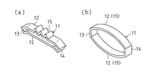
図1に示すように、発泡充填具11は、板状をなす一対の発泡部12、及び各発泡部12のそれぞれ両端を連結する第1の係止部13と第2の係止部14を備え、全体として環状に形成されている。発泡部12は、発泡材料から形成されることで、外部加熱により発泡するように構成されるとともに、弾性変形可能に構成されている。発泡部12の形状はピラー31内部の形状や発泡部12の発泡倍率を考慮して適宜設定される。この発泡充填具11における発泡部12、第1の係止部13及び第2の係止部14が同一の発泡材料から一体成形されている。
As shown in FIG. 1, the
発泡材料は、発泡部12の弾性を考慮して適宜選択すればよい。通常、発泡材料は合成樹脂、発泡剤、架橋剤、充填剤等を含有して構成される。合成樹脂としては熱硬化性樹脂や熱可塑性樹脂が挙げられる。熱硬化性樹脂としてはエポキシ樹脂、フェノール樹脂、ウレタン樹脂、アクリル樹脂等が挙げられる。熱可塑性樹脂としてはポリオレフィン、EVA(エチレン/ビニルアセテートコポリマー)、EPM(エチレン/プロピレンゴム)、SBS(スチレン/ブタジエン/スチレンブロックコポリマー)等が挙げられる。発泡剤としてはアゾジカルボンアミド、ジニトロペンタメチレンテトラミン等、架橋剤としては周知のジメチルウレア、ジシアンジアミド、充填剤としては炭酸カルシウム、硫酸バリウム、フェライト、シリカ等が挙げられる。
The foam material may be appropriately selected in consideration of the elasticity of the
さらに、一方の発泡部12における中央部分は、外方に膨出するように形成されることで、一方の発泡部12の中央部分には、伸縮部15が設けられている。この伸縮部15は、各係止部13,14を結ぶ直線が延びる方向に対して異方向に延びる形状、すなわち円弧状をなし、各係止部13,14の離間及び接近に伴って弾性的に伸縮可能に構成されている。
Furthermore, the center part in one
補強部材34の両側には、それぞれ第1の被係止部16及び第2の被係止部17が凹設されている。発泡充填具11は、これら第1の被係止部16及び第2の被係止部17にそれぞれ第1の係止部13及び第2の係止部14が係止することにより、補強部材34に固定される。図2(b)に示すように、各係止部13,14は、それらの間隔を各被係止部16,17の間隔と異なる間隔となるように配設されている。本実施形態における各係止部13,14の間隔は、各被係止部16,17の間隔よりも狭く設定されている。なお、各係止部13,14の間隔及び各被係止部16,17の間隔は、各係止部13,14が各被係止部16,17に接触する部分を基準にすればよい。すなわち、各係止部13,14の間隔は、各係止部13,14の内面同士の間隔aとし、各被係止部16,17の間隔は、各被係止部16,17の内端部同士の間隔bとすればよい。この間隔aは、間隔bよりも狭く設定される。
On both sides of the reinforcing
さて、この発泡充填具11を使用するには、まず発泡充填具11の内側を広げるようにして発泡部12を弾性変形させる。このとき、発泡部12には伸縮部15が設けられているため、発泡部12自体の弾性変形に加えて、伸縮部15の延びを利用して各係止部13,14を離間させることができる。続いて、発泡充填具11を補強部材34に被せるようにして、第1の係止部13及び第2の係止部14の位置をそれぞれ第1の被係止部16及び第2の被係止部17の位置に合わせることにより、補強部材34に対する発泡充填具11の位置決めを行う。
In order to use the
次いで、発泡部12の弾性を利用して第1の係止部13及び第2の係止部14をそれぞれ第1の被係止部16及び第2の被係止部17に係止させる。このとき、発泡部12は弾性変形可能であるとともに、発泡部12に引張荷重が加わっていない初期状態(係止前の状態)において、第1の係止部13及び第2の係止部14の間隔は、第1の被係止部16及び第2の被係止部17の間隔よりも狭く設定されている。すなわち、第1の係止部13及び第2の係止部14は、その間隔が発泡部12の弾性変形によって変化されて、それぞれ第1の被係止部16及び第2の被係止部17に係止されるように構成されている。そのため、各被係止部16,17に各係止部13,14が係止した係止状態において、発泡部12の弾性力によって、各係止部13,14間には張力が発生する。すなわち、各被係止部16,17に対する各係止部13,14の係止は、発泡部12の弾性力に基づく張力を利用して行われる。そして、発泡充填具11は図1に二点鎖線で示すように補強部材34の外周を取り囲むようにして装着され、補強部材34に固定される。
Next, the
発泡充填具11が固定された補強部材34は、インナパネル32及びアウタパネル33の間に配置され、各パネルの鍔部35及び補強部材34の鍔部35同士が溶接等によって接合される。そして、図2(a)に示すピラー31が製造される。このピラー31において、発泡充填具11の発泡部12は補強部材34の両側における空隙にそれぞれ配置されている。このピラー31は車両ボディの一部を構成し、その車両ボディには、電着塗装、焼付塗装等の塗装が施される。発泡充填具11は、車両の製造工程において、車両ボディが乾燥炉内で加熱される際に、所定温度で所定時間加熱される。その外部加熱に伴って、図2(a)に二点鎖線で示すように発泡部12の発泡(膨張)が開始される。そして、発泡材料に含有する合成樹脂の架橋反応等によって発泡した発泡部12が硬化することにより、図2(c)に示すように発泡体18が形成され、ピラー31の内部における空隙に発泡体18が充填される。この発泡体18によってピラー31の吸音性、遮音性、制振性、防塵性等が高められる。
The reinforcing
本実施形態によって発揮される効果について、以下に記載する。
(1) 発泡部12は弾性変形可能であるとともに、その発泡部12には少なくとも2つの係止部である第1の係止部13及び第2の係止部14が設けられている。これら第1の係止部13及び第2の係止部14の間隔は、少なくとも2つの係止部である第1の被係止部16及び第2の被係止部17の間隔よりも狭く設定されている。すなわち、第1の係止部13及び第2の係止部14は、その間隔が発泡部12の弾性変形によって変化されて、それぞれ第1の被係止部16及び第2の被係止部17に係止されるように構成されている。
The effects exhibited by this embodiment will be described below.
(1) The foamed
そのため、各被係止部16,17に各係止部13,14が係止した状態において、発泡部12の弾性力によって、各係止部13,14間には張力が発生する。すなわち、各被係止部16,17に対する各係止部13,14の係止は、各係止部13,14の形状や弾性力のみに依存することなく、発泡部12の弾性力に基づく張力を利用して行われるようになる。従って、各係止部13,14の形状について複雑化を招くことがなく、係止部の形状を簡易な形状とすることができる結果、発泡充填具11全体を簡易な形状とすることができる。従って、発泡充填具11の生産性を向上することができる。
Therefore, in a state where the locking
また一方、発泡充填具11は、各被係止部16,17に各係止部13,14を合わせて、補強部材34に装着することができる。すなわち、少なくとも2つの係止部と少なくとも2つの被係止部との関係を利用して、補強部材34に対する発泡充填具11の位置決めを行うことができるため、発泡充填具11を容易に装着することができる。
On the other hand, the
(2) この発泡充填具11の発泡部12には伸縮部15が設けられているため、発泡部12自体の弾性変形に加え、伸縮部15の伸びを利用して各係止部13,14を離間させることができる。従って、各係止部13,14を各被係止部16,17に容易に係止させることができる結果、補強部材34に発泡充填具11を装着するに際し、その作業性を向上させることができる。
(2) Since the expansion /
(3) この発泡充填具11には、発泡部12が一対設けられ、それらの両端に第1の係止部13及び第2の係止部14が設けられている。このように発泡充填具11の全体を環状に構成した場合、発泡充填具11が補強部材34の外周を取り囲むように装着されることで、一対の発泡部12は補強部材34の両側に位置する二つの空隙にそれぞれ配置されるようになる。すなわち、1つの発泡充填具11の装着によって、各空隙にはそれぞれ発泡部12が配置されるようになる。従って、各空隙にそれぞれ別の充填具を装着する場合と比べて、装着作業の効率化を図ることができるとともに、装着する発泡充填具11の個数を減らすことができる。このように、インナパネル32及びアウタパネル33によって形成される内部の空隙が補強部材34によって区画されているピラー31に対し、本実施形態の発泡充填具11を適用することで、補強部材34の両側における空隙のいずれにも発泡体18を充填することができる。
(3) The
(4)この発泡充填具11では、各係止部13,14及び各発泡部12は、同一の発泡材料から構成されている。従って、この発泡充填具11は、例えば射出成形、プレス成形等の成形法により製造することが可能となるため、発泡充填具11の生産性を向上することができる。
(4) In this
(5)発泡部12及び各係止部13,14を同一の発泡材料から一体成形されているため、発泡部12及び各係止部13,14には、異種材料からなる部材を結合している部分が存在しない。そのため、発泡部12から各係止部13,14が脱落することを抑制することができる。その結果、輸送時や装着時における発泡充填具11の取り扱い性を向上することができる。
(5) Since the foamed
なお、前記実施形態を次のように変更して構成してもよい。
・ 図3(a)及び図3(b)に示すように、発泡部12の一方を省略してもよい。すなわち、発泡部12の両端に断面C字状の第1の係止部13及び第2の係止部14をそれぞれ設けて発泡充填具11を構成してもよい。このように構成した場合、上記(1)、(2)、(4)及び(5)と同じ作用効果が得られる。
The embodiment may be modified as follows.
-As shown in Drawing 3 (a) and Drawing 3 (b), you may omit one side of foaming
・ いずれか一方の発泡部12を分割構成することで、3つ以上の発泡部12を有する構成としてもよい。例えば、伸縮部15を発泡材料以外の弾性材料、すなわち発泡剤を含有しない合成樹脂等から形成することで、発泡部12が2分割された構成としてもよい。また例えば、少なくとも一方の発泡部12に切り欠き部分が形成されることで、その発泡部12が2分割された構成としてもよい。
-It is good also as a structure which has the 3 or
・ 図4(a)及び図4(b)に示すように、例えば補強部材34を有しない中空構造部材において、インナパネル32に発泡充填具11を固定するように構成してもよい。すなわち、インナパネル32の内側に突起状の第1の被係止部16及び第2の被係止部17を所定の間隔で設け、それら被係止部16,17にそれぞれ第1の係止部13及び第2の係止部14を係止する。このとき、係止前の状態における第1の係止部13及び第2の係止部14の間隔は、第1の被係止部16及び第2の被係止部17の間隔よりも狭く設定される。なお、第1の被係止部16及び第2の被係止部17をアウタパネル33に設け、アウタパネル33の内側に発泡充填具11を固定するように構成してもよい。
-As shown in Drawing 4 (a) and Drawing 4 (b), you may comprise so that
・ 図4(a)及び図4(b)に示すように、伸縮部15を省略してもよい。
・ 図5(a)及び図5(b)に示すように、第1の係止部13及び第2の係止部14をそれぞれ複数設けてもよい。すなわち、発泡部12の内側に突起状の第1の係止部13及び第2の係止部14をさらに設ける一方、補強部材34に円孔状の第1の被係止部16及び第2の被係止部17を貫設する。そして、突起状の各係止部13,14はそれぞれ円孔状の各被係止部16,17に挿入されて係止されるように構成してもよい。
-As shown in Drawing 4 (a) and Drawing 4 (b),
-As shown to Fig.5 (a) and FIG.5 (b), you may provide multiple 1st latching | locking
・ 各係止部13,14の形状は、各被係止部16,17の形状に合わせて形成すればよい。すなわち、各係止部13,14の形状は、穴、孔、溝等に変更してもよいし、第1の係止部13及び第2の係止部14は互いに異なる形状であってもよい。
-The shape of each latching | locking
・ 第1の係止部13及び第2の係止部14の間隔を、第1の被係止部16及び第2の被係止部17の間隔よりも広く設定してもよい。例えば、図6(a)及び図6(b)に示すように、長四角板状の発泡部12に断面L字状の第1の係止部13及び第2の係止部14を設ける一方、補強部材34に長四角形状の第1の被係止部16及び第2の被係止部17を貫設する。図6(c)に示すように、係止前の状態における第1の係止部13の及び第2の係止部14の間隔cは、第1の被係止部16及び第2の被係止部17の間隔dよりも広く設定される。なお、各係止部13,14の間隔c及び各被係止部16,17の間隔dは、各係止部13,14が各被係止部16,17に接触する部分を基準にすればよい。この発泡充填具11を装着するには、まず発泡部12を弾性変形、すなわち湾曲させることで、各係止部13,14を接近させる。続いて、各係止部13,14をそれぞれ各被係止部16,17に係止させる。このように構成した場合でも前記実施形態と同様に、発泡部12の弾性力(収縮力)によって各係止部13,14間には張力が発生する。その結果、上記(1)、(4)及び(5)と同じ効果を得ることができる。
The interval between the
・ 第1の係止部13及び第2の係止部14を発泡材料以外の材料によって形成してもよい。この場合、例えば発泡部12と各係止部13,14を別体で形成した後に、これらの発泡部12及び各係止部13,14を接着剤、インサート成形等によって一体にすることで、発泡充填具11を形成することができる。
-You may form the 1st latching | locking
・ 図7(a)に示すように、伸縮部15を断面波形状に変更してもよい。図7(b)に示すように、発泡部12を湾曲形成することで、発泡部12全体を伸縮部15として機能するように構成してもよい。
-As shown to Fig.7 (a), you may change the expansion-
・ 発泡充填具11を適用するピラー31の断面形状、補強部材34の個数は特に限定されない。さらには、発泡充填具11をフロントピラー、センターピラー等のピラー以外の中空構造部材、例えばロッカーパネル、ドアの内部、建造物における各種中空パネル等に使用してもよい。
-The cross-sectional shape of the
11…発泡充填具、12…発泡部、13…第1の係止部、14…第2の係止部、15…伸縮部、16…第1の被係止部、17…第2の被係止部、18…発泡体、31…ピラー、32…インナパネル、33…アウタパネル、34…補強部材、35…鍔部。
DESCRIPTION OF
Claims (5)
前記発泡部は弾性変形可能であるとともに、前記発泡部には中空構造部材の内部に係止する少なくとも2つの係止部が設けられ、
前記少なくとも2つの係止部の間隔が前記発泡部の弾性変形により変化されることで、前記各係止部が前記中空構造部材に設けられる少なくとも2つの被係止部に係止されることを特徴とする発泡充填具。 In a foam filling device that includes a foaming portion that foams by external heating and is fixed inside a hollow structural member,
The foamed portion is elastically deformable, and the foamed portion is provided with at least two locking portions that are locked inside the hollow structural member,
The interval between the at least two locking portions is changed by elastic deformation of the foamed portion, whereby each locking portion is locked to at least two locked portions provided in the hollow structural member. Characteristic foam filler.
前記発泡部は弾性変形可能であるとともに、前記発泡部には前記中空構造部材に係止する係止部が設けられ、
前記係止部は、前記中空構造部材に設けられる第1の被係止部に係止される第1の係止部と、前記中空構造部材に設けられる第2の被係止部に係止される第2の係止部と、を備え、
前記第1の係止部及び第2の係止部を、前記第1の被係止部及び第2の被係止部の間隔と異なる間隔で配設したことを特徴とする発泡充填具。 In a foam filling device that includes a foaming portion that foams by external heating and is fixed inside a hollow structural member,
The foaming part is elastically deformable, and the foaming part is provided with a locking part for locking to the hollow structural member,
The locking portion is locked to a first locking portion locked to a first locked portion provided in the hollow structure member and a second locked portion provided to the hollow structure member. A second locking portion,
The foam filler according to claim 1, wherein the first locking portion and the second locking portion are arranged at intervals different from the interval between the first locked portion and the second locked portion.
Priority Applications (1)
| Application Number | Priority Date | Filing Date | Title |
|---|---|---|---|
| JP2004314425A JP4451273B2 (en) | 2004-10-28 | 2004-10-28 | Foam filler |
Applications Claiming Priority (1)
| Application Number | Priority Date | Filing Date | Title |
|---|---|---|---|
| JP2004314425A JP4451273B2 (en) | 2004-10-28 | 2004-10-28 | Foam filler |
Publications (2)
| Publication Number | Publication Date |
|---|---|
| JP2006123710A true JP2006123710A (en) | 2006-05-18 |
| JP4451273B2 JP4451273B2 (en) | 2010-04-14 |
Family
ID=36718852
Family Applications (1)
| Application Number | Title | Priority Date | Filing Date |
|---|---|---|---|
| JP2004314425A Expired - Fee Related JP4451273B2 (en) | 2004-10-28 | 2004-10-28 | Foam filler |
Country Status (1)
| Country | Link |
|---|---|
| JP (1) | JP4451273B2 (en) |
Cited By (8)
| Publication number | Priority date | Publication date | Assignee | Title |
|---|---|---|---|---|
| WO2009117376A1 (en) * | 2008-03-17 | 2009-09-24 | Zephyros,Inc. | Insert with integrated fastener |
| JP2013504460A (en) * | 2009-09-15 | 2013-02-07 | ゼフィロス インコーポレイテッド | Improvement of cavity filler |
| US8790058B2 (en) | 2011-08-15 | 2014-07-29 | Zephyros, Inc. | Push-pin cavity sealer |
| US8918983B2 (en) | 2011-06-21 | 2014-12-30 | Zephyros, Inc. | Integrated fastening system |
| US8967327B2 (en) | 2012-03-20 | 2015-03-03 | Zephyros, Inc. | Baffle assembly |
| US9010843B2 (en) | 2012-06-08 | 2015-04-21 | Zephyros, Inc. | Partial-filled baffle |
| USD751887S1 (en) | 2015-01-26 | 2016-03-22 | Zephyros, Inc. | Sealer |
| US9713885B2 (en) | 2010-12-08 | 2017-07-25 | Zephyros, Inc. | Sealing assembly |
-
2004
- 2004-10-28 JP JP2004314425A patent/JP4451273B2/en not_active Expired - Fee Related
Cited By (12)
| Publication number | Priority date | Publication date | Assignee | Title |
|---|---|---|---|---|
| WO2009117376A1 (en) * | 2008-03-17 | 2009-09-24 | Zephyros,Inc. | Insert with integrated fastener |
| JP2011514289A (en) * | 2008-03-17 | 2011-05-06 | ゼフィロス インコーポレイテッド | Integral fastener insert |
| US8758535B2 (en) | 2008-03-17 | 2014-06-24 | Zephyros, Inc. | Insert with integrated fastener |
| US10363975B2 (en) | 2008-03-17 | 2019-07-30 | Zephyros, Inc. | Insert with integrated fastener |
| JP2013504460A (en) * | 2009-09-15 | 2013-02-07 | ゼフィロス インコーポレイテッド | Improvement of cavity filler |
| US9713885B2 (en) | 2010-12-08 | 2017-07-25 | Zephyros, Inc. | Sealing assembly |
| US8918983B2 (en) | 2011-06-21 | 2014-12-30 | Zephyros, Inc. | Integrated fastening system |
| US8790058B2 (en) | 2011-08-15 | 2014-07-29 | Zephyros, Inc. | Push-pin cavity sealer |
| US8967327B2 (en) | 2012-03-20 | 2015-03-03 | Zephyros, Inc. | Baffle assembly |
| US9010843B2 (en) | 2012-06-08 | 2015-04-21 | Zephyros, Inc. | Partial-filled baffle |
| US9776368B2 (en) | 2012-06-08 | 2017-10-03 | Zephyros, Inc. | Partial-filled baffle |
| USD751887S1 (en) | 2015-01-26 | 2016-03-22 | Zephyros, Inc. | Sealer |
Also Published As
| Publication number | Publication date |
|---|---|
| JP4451273B2 (en) | 2010-04-14 |
Similar Documents
| Publication | Publication Date | Title |
|---|---|---|
| JP2002362412A (en) | Reinforcement structure of hollow panel and reinforcement tool therefor | |
| JP2001199362A (en) | Reinforcing tool for hollow structure | |
| JPH08276448A (en) | Support structure of foamable material for hollow structure | |
| WO2020163822A1 (en) | Attachment systems for pultruded, extruded, and molded parts | |
| JP2001088739A (en) | Hollow structure charging-in structure and method thereof | |
| JP4451273B2 (en) | Foam filler | |
| JP2003226261A (en) | Reinforcement structure and method for hollow structure | |
| US10480556B1 (en) | Member joining method | |
| JPH08282396A (en) | Support structure of foaming material for hollow structure | |
| JP4472583B2 (en) | Foaming tools | |
| JP3516806B2 (en) | Supporting structure of foamable substrate in hollow structure | |
| JP5848886B2 (en) | Foam filler, method for producing structure obtained using the same, and method for filling foam | |
| JP5876315B2 (en) | Spacer member | |
| JP3819139B2 (en) | Hollow chamber blocking structure for hollow structures | |
| CN101602242B (en) | Foam filling member | |
| JP4452606B2 (en) | Foam filler | |
| JP5300704B2 (en) | Expandable filler | |
| US10953823B2 (en) | Oscillation decoupled cable guide device | |
| JP5508882B2 (en) | Effervescent filler | |
| JP6155113B2 (en) | Foam filler | |
| JP5566985B2 (en) | Foam filler | |
| KR102368434B1 (en) | Foam pad of metal carrier | |
| KR100475788B1 (en) | Door for preventing a noise for vehicles | |
| JP2009073105A (en) | Foam filling instrument and reinforcing method of long hollow structure | |
| JP2025005123A (en) | Opening frame structure |
Legal Events
| Date | Code | Title | Description |
|---|---|---|---|
| A621 | Written request for application examination |
Free format text: JAPANESE INTERMEDIATE CODE: A621 Effective date: 20061122 |
|
| A131 | Notification of reasons for refusal |
Free format text: JAPANESE INTERMEDIATE CODE: A131 Effective date: 20090519 |
|
| A977 | Report on retrieval |
Free format text: JAPANESE INTERMEDIATE CODE: A971007 Effective date: 20090521 |
|
| A521 | Written amendment |
Free format text: JAPANESE INTERMEDIATE CODE: A523 Effective date: 20090721 |
|
| TRDD | Decision of grant or rejection written | ||
| A01 | Written decision to grant a patent or to grant a registration (utility model) |
Free format text: JAPANESE INTERMEDIATE CODE: A01 Effective date: 20100112 |
|
| A01 | Written decision to grant a patent or to grant a registration (utility model) |
Free format text: JAPANESE INTERMEDIATE CODE: A01 |
|
| A61 | First payment of annual fees (during grant procedure) |
Free format text: JAPANESE INTERMEDIATE CODE: A61 Effective date: 20100127 |
|
| R150 | Certificate of patent or registration of utility model |
Ref document number: 4451273 Country of ref document: JP Free format text: JAPANESE INTERMEDIATE CODE: R150 Free format text: JAPANESE INTERMEDIATE CODE: R150 |
|
| FPAY | Renewal fee payment (event date is renewal date of database) |
Free format text: PAYMENT UNTIL: 20130205 Year of fee payment: 3 |
|
| FPAY | Renewal fee payment (event date is renewal date of database) |
Free format text: PAYMENT UNTIL: 20160205 Year of fee payment: 6 |
|
| R250 | Receipt of annual fees |
Free format text: JAPANESE INTERMEDIATE CODE: R250 |
|
| R250 | Receipt of annual fees |
Free format text: JAPANESE INTERMEDIATE CODE: R250 |
|
| LAPS | Cancellation because of no payment of annual fees |