JP2006123771A - Track loading space lower part structure - Google Patents
Track loading space lower part structure Download PDFInfo
- Publication number
- JP2006123771A JP2006123771A JP2004315663A JP2004315663A JP2006123771A JP 2006123771 A JP2006123771 A JP 2006123771A JP 2004315663 A JP2004315663 A JP 2004315663A JP 2004315663 A JP2004315663 A JP 2004315663A JP 2006123771 A JP2006123771 A JP 2006123771A
- Authority
- JP
- Japan
- Prior art keywords
- vertical
- joist
- truck bed
- joists
- fixing
- Prior art date
- Legal status (The legal status is an assumption and is not a legal conclusion. Google has not performed a legal analysis and makes no representation as to the accuracy of the status listed.)
- Granted
Links
- 238000012856 packing Methods 0.000 claims abstract description 26
- 239000000463 material Substances 0.000 claims abstract description 24
- 238000009434 installation Methods 0.000 abstract 1
- 238000003466 welding Methods 0.000 description 4
- 229920003002 synthetic resin Polymers 0.000 description 3
- 239000000057 synthetic resin Substances 0.000 description 3
- 239000000853 adhesive Substances 0.000 description 2
- 230000001070 adhesive effect Effects 0.000 description 2
- 230000009466 transformation Effects 0.000 description 2
- BZHJMEDXRYGGRV-UHFFFAOYSA-N Vinyl chloride Chemical compound ClC=C BZHJMEDXRYGGRV-UHFFFAOYSA-N 0.000 description 1
- 239000002390 adhesive tape Substances 0.000 description 1
- 239000012141 concentrate Substances 0.000 description 1
- 230000000694 effects Effects 0.000 description 1
Images


Landscapes
- Body Structure For Vehicles (AREA)
Abstract
Description
本発明は、荷台をトラックのシャーシに取り付けるためのトラック荷台下部構造に関する。 The present invention relates to a truck bed lower structure for attaching a bed to a truck chassis.
トラックには、その後方に、荷物を積載する荷台が備えられている。荷台は、床板の裏面に取り付けたクロスビーム構造体すなわちトラック荷台下部構造を介してトラックのシャーシに取り付けられている。このトラック荷台下部構造は、シャーシに固定される角筒状の縦根太と、この縦根太と交差して縦根太の上面に固定される角筒状の横根太とから構成され、床板は、横根太上に取り付けられている。 The truck is provided with a loading platform on the rear side of which loads are loaded. The loading platform is attached to the truck chassis via a cross beam structure attached to the back surface of the floor plate, that is, a truck loading platform lower structure. This truck bed lower structure is composed of a square tube-shaped vertical joist fixed to the chassis and a square tube-shaped horizontal joist fixed to the upper surface of the vertical joist across the vertical joist, and the floor board Attached to the top.
そして、従来のトラック荷台下部構造では、縦根太は、シャーシの上面との滑りを防止するため、塩化ビニルなどの合成樹脂からなる帯状のパッキン材を介してシャーシの上面に固定されている(例えば、特許文献1を参照)。 And in the conventional truck bed lower structure, the vertical joist is fixed to the upper surface of the chassis via a band-shaped packing material made of a synthetic resin such as vinyl chloride in order to prevent slippage with the upper surface of the chassis (for example, , See Patent Document 1).
また、縦根太の側面には、縦根太の長手方向に長い断面C字形の側面溝が形成され、この側面溝内にボルトの頭を嵌入することにより、縦根太と横根太やシャーシとを接合板で取り付ける作業や、必要に応じて、送油配管や配電線を取り付ける作業を容易に行えるようにしている(例えば、特許文献2を参照)。
しかし、従来のトラック荷台下部構造では、縦根太は、パッキン材が、両面粘着テープで、縦根太の幅方向にわたって平坦な下面と、シャーシの幅方向にわたって平坦な上面に貼り付けられているだけなので、トラックの振動や発進・停止の際にパッキン材に作用する慣性力、遠心力などにより、パッキン材のズレが生じ、その結果、トラック荷台下部構造を構成する成分同士を連結する部品に過度な応力が作用し、この部品が変形したり破損するという問題が生じる。 However, in the conventional truck bed bottom structure, the vertical joist is only affixed to the bottom surface flat across the width direction of the vertical joist and the flat upper surface across the width direction of the chassis with double-sided adhesive tape. The packing material is displaced due to the inertial force, centrifugal force, etc. acting on the packing material when the truck vibrates or starts / stops. As a result, the components that make up the truck bed bottom structure are excessively connected to the parts. The stress acts, causing a problem that the part is deformed or broken.
また、横根太が、角筒状の縦根太の上面の一方のエッジから他方のエッジにわたって接触しているので、トラックの振動や発進・停止の際に横根太に作用する慣性力、遠心力などにより、縦根太のエッジ部分に応力が集中すると、縦根太の側面に形成した断面C字形の側面溝が変形し、この側面溝内にボルトの頭を嵌入させることができず、所定の個所に、縦根太と横根太やシャーシとを取り付けたり、送油配管や配電線を取り付けることが容易に行えない、という問題が生じる。 Also, because the horizontal joist is in contact from one edge to the other edge of the top surface of the square tube-shaped vertical joist, the inertial force, centrifugal force, etc. that act on the horizontal joist when the truck vibrates or starts / stops Thus, when stress concentrates on the edge of the vertical joist, the side groove with a C-shaped cross section formed on the side surface of the vertical joist is deformed, and the bolt head cannot be fitted into this side groove, so that There arises a problem that vertical joists, horizontal joists, and chassis, and oil supply pipes and distribution lines cannot be easily attached.
したがって、本発明の目的は、パッキン材をシャーシの上面と縦根太の下面との間に確実に配置できるトラック荷台下部構造を提供することである。 Accordingly, an object of the present invention is to provide a truck bed lower structure in which the packing material can be reliably disposed between the upper surface of the chassis and the lower surface of the vertical joists.
また、本発明の他の目的は、所定の個所に、縦根太と横根太やシャーシとを容易に取り付けることができるトラック荷台下部構造を提供することである。 Another object of the present invention is to provide a truck bed lower structure in which a vertical joist, a horizontal joist, and a chassis can be easily attached at predetermined positions.
上記目的を達成する本発明のトラック荷台下部構造は、トラックのシャーシに荷台を取り付けるためのものである。 The truck bed lower structure according to the present invention that achieves the above object is for attaching a bed to a truck chassis.
本発明のトラック荷台下部構造は、パッキン材を介してシャーシの上面に配置される角筒状の縦根太、縦根太をシャーシに固定するための第一の固定手段、縦根太と交差して縦根太の上面に配置される角筒状の横根太、及び横根太を縦根太に固定するための第二の固定手段から構成される。 The lower structure of the truck bed according to the present invention is a rectangular tube-like vertical joist disposed on the upper surface of the chassis via a packing material, a first fixing means for fixing the vertical joist to the chassis, and the vertical joist crossing the vertical joist. It is composed of a rectangular tube-shaped horizontal joist disposed on the upper surface of the joist and a second fixing means for fixing the horizontal joist to the vertical joist.
縦根太の下面に、縦根太の長手方向に長い断面コ字形の下面溝が形成され、この下面溝内にパッキン材が配置される。これにより、パッキン材が、シャーシの上面と縦根太の下面との間に確実に配置される。このパッキン材は、シャーシの上面に対する縦根太の滑りを防止するものであり、合成樹脂からなる帯状のものであり、粘着剤で、縦根太の下面溝内に貼り付けて配置させることができる。 A bottom groove having a U-shaped cross section that is long in the longitudinal direction of the vertical joist is formed on the lower face of the vertical joist, and a packing material is disposed in the lower groove. Thereby, a packing material is reliably arrange | positioned between the upper surface of a chassis, and the lower surface of a vertical joist. This packing material prevents slipping of the vertical joist with respect to the upper surface of the chassis, is a belt-like thing made of synthetic resin, and can be disposed by being stuck in the lower groove of the vertical joist with an adhesive.
第一の固定手段は、縦根太の側面とシャーシの側面に面した取付面を有する第一の接合板、この第一の接合板をシャーシの側面に固定するための手段、及び第一の接合板を縦根太に固定するための第一のボルト手段から構成される。 The first fixing means includes a first joint plate having a side face of the vertical joist and a mounting surface facing the side face of the chassis, means for fixing the first joint plate to the side face of the chassis, and the first joint It is comprised from the 1st bolt means for fixing a board to a vertical joist.
第一の接合板をシャーシの側面に固定するための手段は、ボルト、スクリュー、リベット、溶接などの既知の手段から選択でき、この既知の手段により、シャーシの側面に面した第一の接合板の取付面がシャーシの側面に取り付けられて、第一の接合板がシャーシの側面に固定される。 The means for fixing the first joining plate to the side of the chassis can be selected from known means such as bolts, screws, rivets, welding, etc., by which the first joining plate facing the side of the chassis. Is attached to the side surface of the chassis, and the first joining plate is fixed to the side surface of the chassis.
縦根太の側面に、縦根太の長手方向に長い1個又は複数個の断面C字形の側面溝が形成され、第一のボルト手段の一端が、この側面溝内に嵌入される。これにより、縦根太の側面に面した第一の接合板の取付面が、縦根太の側面に取り付けられ、第一の接合板が縦根太に固定される。 One or a plurality of side grooves having a C-shaped cross section that are long in the longitudinal direction of the vertical joists are formed on the side faces of the vertical joists, and one end of the first bolt means is fitted into the side grooves. Thereby, the attachment surface of the first joining plate facing the side surface of the vertical joist is attached to the side surface of the vertical joist, and the first joining plate is fixed to the vertical joist.
この側面溝を形成した側の縦根太の上面のエッジ部分に、下方向に傾斜する傾斜面が形成される。これにより、縦根太の上面のエッジ部分に横根太の下面が接しないので、縦根太の側面溝が、荷重により変形することがない。このような傾斜面は、ほぼ真直ぐに下向きに傾斜していてもよいし、丸く下方へ傾斜していてもよい。 An inclined surface inclined downward is formed at the edge portion of the upper surface of the vertical joist on the side where the side groove is formed. Thereby, since the lower surface of the horizontal joist does not contact the edge portion of the upper surface of the vertical joist, the side groove of the vertical joist is not deformed by the load. Such an inclined surface may be inclined substantially straight downward or may be inclined downward in a round shape.
好適に、縦根太の上面に、縦根太の長手方向に長い1個又は複数個の断面C字形の上面溝が、さらに形成される。このとき、第一の固定手段は、変形的に、縦根太の上面とシャーシの側面に面した取付面を有する第一の接合板、この第一の接合板をシャーシの側面に固定するための手段、及び第一の接合板を縦根太に固定するための第一のボルト手段から構成され、この第一のボルト手段の一端が、縦根太の上面溝内に嵌入される。 Preferably, one or more upper surface grooves having a C-shaped cross section that are long in the longitudinal direction of the vertical joists are further formed on the upper surface of the vertical joists. At this time, the first fixing means deformably, a first joint plate having a mounting surface facing the upper surface of the vertical joist and the side surface of the chassis, for fixing the first joint plate to the side surface of the chassis And a first bolt means for fixing the first joining plate to the vertical joist, and one end of the first bolt means is fitted into the upper face groove of the vertical joist.
第二の固定手段は、第二の接合板、この第二の接合板を横根太の側面に固定するための手段、及びこの第二の接合板を縦根太に固定するための手段から構成される。 The second fixing means includes a second joining plate, means for fixing the second joining plate to the side surface of the horizontal joist, and means for fixing the second joining plate to the vertical joist. The
第二の接合板として、横根太の側面と縦根太の側面に面する取付面を有するものが使用できる。このとき、第二の接合板を横根太の側面に固定するための手段と第二の接合板を縦根太に固定するための手段は、それぞれ、ボルト、スクリュー、リベット、溶接などの既知の手段から選択でき、この既知の手段により、横根太の側面と縦根太の側面に面した第二の接合板の取付面が横根太の側面と縦根太の側面に取り付けられて、第二の接合板が横根太の側面と縦根太の側面に固定される。好適に、第二の接合板を縦根太に固定するための手段は、第二のボルト手段であり、この第二のボルト手段の一端が、縦根太の側面溝内に嵌入される。 As the second bonding plate, one having a mounting surface facing the side surface of the horizontal joist and the side surface of the vertical joist can be used. At this time, the means for fixing the second joining plate to the side surface of the horizontal joist and the means for fixing the second joining plate to the vertical joist are known means such as bolts, screws, rivets, and welding, respectively. By this known means, the mounting surface of the second joint plate facing the side surface of the horizontal joist and the side surface of the vertical joist is attached to the side surface of the horizontal joist and the side surface of the vertical joist. Is fixed to the side of the horizontal joist and the side of the vertical joist. Preferably, the means for fixing the second joining plate to the vertical joist is the second bolt means, and one end of the second bolt means is fitted in the side groove of the vertical joist.
また、この第二の接合板として、横根太の側面と縦根太の上面に面する取付面を有するものを使用してもよい。このとき、第二の接合板を横根太の側面に固定するための手段と第二の接合板を縦根太に固定するための手段は、それぞれ、上記の既知の手段から選択でき、この既知の手段により、横根太の側面と縦根太の上面に面した第二の接合板の取付面が横根太の側面と縦根太の上面に取り付けられて、第二の接合板が横根太の側面と縦根太の上面に固定される。 Moreover, you may use what has an attachment surface which faces the side surface of a horizontal joist and the upper surface of a vertical joist as this 2nd joining board. At this time, the means for fixing the second joining plate to the side surface of the horizontal joist and the means for fixing the second joining plate to the vertical joist can be selected from the above-mentioned known means, respectively. The mounting surface of the second joint plate facing the side surface of the horizontal joist and the upper surface of the vertical joist is attached to the side surface of the horizontal joist and the upper surface of the vertical joist, and the second joint plate is vertically aligned with the side surface of the horizontal joist. Fixed to the upper surface of the joist.
好適に、縦根太の上面に、縦根太の長手方向に長い断面C字形の上面溝が、さらに形成され、このとき、横根太の側面と縦根太の上面に面する取付面を有する上記の第二の接合板は、変形的に、一端がこの上面溝内に嵌入される第二のボルト手段によって、縦根太に固定される。 Preferably, an upper surface groove having a C-shaped cross section that is long in the longitudinal direction of the vertical joists is further formed on the upper surface of the vertical joists, and at this time, the above-mentioned first having the side surfaces of the horizontal joists and the mounting surfaces facing the upper surfaces of the vertical joists The two joining plates are deformably fixed to the vertical joists by the second bolt means whose one end is inserted into the upper surface groove.
ここで、縦根太の上面に面する第二の接合板の取付面の幅は、縦根太のエッジ部分の傾斜面の開始点と、これと反対側の縦根太のエッジとの間の距離と同じ、又はこの距離よりも長い。これにより、荷重による第二の接合板の変形が防止される。 Here, the width of the mounting surface of the second joining plate facing the upper surface of the vertical joist is the distance between the starting point of the inclined surface of the edge portion of the vertical joist and the edge of the vertical joist on the opposite side. Same or longer than this distance. Thereby, the deformation | transformation of the 2nd joining board by a load is prevented.
好適に、横根太として、C字形の断面を有するものが使用され、このとき、第二の固定手段は、この横根太の下面を縦根太に固定するための第三のボルト手段からさらに構成され、この第三のボルト手段の一端が、縦根太の上面溝内に嵌入される。 Preferably, a horizontal joist having a C-shaped cross section is used, wherein the second fixing means further comprises third bolt means for fixing the lower surface of the horizontal joist to the vertical joist. One end of the third bolt means is fitted into the upper face groove of the vertical joist.
また、この縦根太として、中空のものが使用され、このとき、この縦根太の内部には、縦根太の内部下面から上面溝の裏面にわたるリブが形成される。これにより、中空の縦根太が補強される。 Moreover, a hollow thing is used as this vertical joist, and at this time, a rib extending from the inner lower surface of the vertical joist to the back surface of the upper surface groove is formed inside the vertical joist. Thereby, a hollow vertical joist is reinforced.
本発明が以上のように構成されるので、以下のような効果を奏する。 Since this invention is comprised as mentioned above, there exist the following effects.
縦根太の下面に、縦根太の長手方向に長い断面コ字形の下面溝を形成し、この下面溝内にパッキン材を配置したので、この下面溝がパッキン材のズレ止めとして機能し、パッキン材をシャーシの上面と縦根太の下面との間に確実に配置できる。 A bottom groove with a U-shaped cross section that is long in the longitudinal direction of the vertical joist is formed on the lower surface of the vertical joist, and a packing material is disposed in the lower groove so that the lower groove functions as a stopper for the packing material, and the packing material Can be reliably disposed between the upper surface of the chassis and the lower surface of the vertical joists.
縦根太の側面に、縦根太の長手方向に長い1個又は複数個の断面C字形の側面溝を形成し、第一の接合板を縦根太に固定するための第一のボルト手段の一端を、この側面溝内に嵌入させるので、縦根太の側面に穴をあける作業をせずに、縦根太の側面に面した第一の接合板の取付面を縦根太の側面に取り付けることができ、これにより、第一の接合板を容易簡単な作業で縦根太に固定できる。また、このような側面溝を複数個形成することで、縦根太の上面の側にある側面溝が荷重により変形しても、その下方にある側面溝を使用して、縦根太の側面に面した第一の接合板の取付面を縦根太の側面に取り付けることができる。さらに、この側面溝を形成した側の縦根太の上面のエッジ部分に、下方向に傾斜する傾斜面を形成したので、縦根太の上面のエッジ部分に横根太の下面が接することがなく、縦根太の側面溝を、荷重により変形させることがない。 One or more side grooves having a C-shaped cross section that are long in the longitudinal direction of the vertical joists are formed on the side surfaces of the vertical joists, and one end of the first bolt means for fixing the first joining plate to the vertical joists is provided. Since it is inserted into this side groove, the mounting surface of the first joining plate facing the side face of the vertical joist can be attached to the side face of the vertical joist, without the work of making a hole in the side face of the vertical joist, Thereby, a 1st joining board can be fixed to a vertical joist by an easy simple operation. In addition, by forming a plurality of such side grooves, even if the side groove on the upper surface side of the vertical joist is deformed by a load, the side groove on the lower side is used to face the side surface of the vertical joist. The attachment surface of the first joining plate can be attached to the side surface of the vertical joist. Furthermore, since the inclined surface inclined downward is formed on the edge portion of the upper surface of the vertical joist on the side where the side groove is formed, the lower surface of the horizontal joist is not in contact with the edge portion of the upper surface of the vertical joist. The joist side groove is not deformed by the load.
縦根太の上面に面する第二の接合板の取付面の幅を、縦根太のエッジ部分の傾斜面の開始点と、これと反対側の縦根太のエッジとの間の距離と同じ、又はこの距離よりも長くしたので、荷重による第二の接合板の変形を防止できる。 The width of the mounting surface of the second joining plate facing the upper surface of the vertical joist is equal to the distance between the starting point of the inclined surface of the edge portion of the vertical joist and the edge of the vertical joist on the opposite side, or Since the distance is longer than this distance, deformation of the second joining plate due to the load can be prevented.
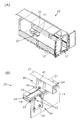
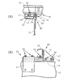
図1Aに示すように、荷物を積載する荷台11が荷箱10の内部に備えられている。荷台11は、床板12の裏面に取り付けたクロスビーム構造体すなわちトラック荷台下部構造20を介してトラックのシャーシ(図1Bに符号13で示す)に取り付けられている。
As shown in FIG. 1A, a
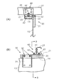
図1B、図2〜図5に、本発明のトラック荷台下部構造20の例を示す。図示のように、本発明のトラック荷台下部構造20は、パッキン材14を介してシャーシ13の上面に配置される角筒状の縦根太21、縦根太21をシャーシ13に固定するための第一の固定手段30、縦根太21と交差して縦根太21の上面に配置される角筒状の横根太27、及び横根太27を縦根太21に固定するための第二の固定手段40から構成される。
1B and 2 to 5 show examples of the truck bed
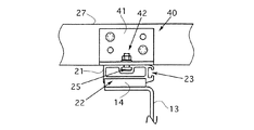
縦根太21の下面に、縦根太21の長手方向に長い断面コ字形の下面溝22が形成され(図6A〜図6Eを参照)、この下面溝22内にパッキン材14が配置される。パッキン材14は、シャーシ13の上面に対する縦根太21の滑りを防止するものであり、合成樹脂からなる帯状のものであり、粘着剤で、縦根太21の下面溝22内に貼り付けて配置させることができる。そして、下面溝22は、パッキン材14の厚さの半分以上の深さにあり、この下面溝22内にパッキン材14の上側の部分の半分以上が収容され、パッキン材14の下側の部分が下面溝22から下側に露出する。これにより、パッキン材14が、シャーシ13の上面と縦根太21の下面との間に確実に配置される。
A
第一の固定手段30は、縦根太21の側面とシャーシ13の側面に面した取付面を有する第一の接合板31、この第一の接合板31をシャーシ13の側面に固定するための手段、及び第一の接合板31を縦根太21に固定するための第一のボルト手段32から構成される。
The first fixing means 30 includes a first
第一の接合板31をシャーシ13の側面に固定するための手段は、ボルト、スクリュー、リベット、溶接などの既知の手段から選択でき、この既知の手段により、シャーシ13の側面に面した第一の接合板31の取付面がシャーシ13の側面に取り付けられて、第一の接合板31がシャーシ13の側面に固定される。図1Bに示す例では、シャーシ13の側面から第一の接合板31の取付面に貫挿させたボルトの先端をナットで締めるボルト手段により、第一の接合板31の取付面がシャーシ13の側面に取り付けられ、これにより、第一の接合板31がシャーシ13の側面に固定されている。
The means for fixing the first joining
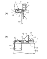
図示の例では、縦根太21の側面に、縦根太21の長手方向に長い1個の断面C字形の側面溝23が形成され、第一のボルト手段32の一端が、この側面溝23内に嵌入される。これにより、縦根太21の側面に面した第一の接合板31の取付面が、縦根太21の側面に取り付けられ、第一の接合板31が縦根太21に固定される。このような側面溝23は、図6A〜図6Eに示すように、縦根太21の側面に複数個形成されてもよく、側面溝23の個数は、適宜に選定できる。また、このような側面溝23を複数個形成することで、仮に、縦根太21の上面の側にある側面溝23が荷重により変形しても、その下方にある側面溝23を使用して、第一の接合板31をシャーシ13に固定できる。
In the illustrated example, one
この側面溝23を形成した側の縦根太21の上面のエッジ部分に、下方向に傾斜する傾斜面24が形成される。これにより、縦根太21の上面のエッジ部分に横根太27の下面が接しないので、縦根太21の側面溝23が、荷重により変形することがない。このような傾斜面24は、図7Aに示すようにほぼ真直ぐに下向きに傾斜していてもよいし、図7Bに示すように、丸く下方へ傾斜していてもよい。このような傾斜面24の傾斜の開始点24´は、縦根太21のエッジ部分に荷重がかかったときに、側面溝23が変形しないような位置であればよく、側面溝23の底面の直上付近にあり、好適に、側面溝23の底面の直上又はこれよりも内側(縦根太21の上面の中央側)にある。
An
縦根太21の上面に、縦根太21の長手方向に長い1個又は複数個の断面C字形の上面溝25が、さらに形成される。このとき、第一の固定手段30は、図4A、B及び図5A、Bに示すように、縦根太21の上面とシャーシ13の側面に面した取付面を有する正面L字形の第一の接合板31、この第一の接合板31をシャーシ13の側面に固定するための手段(この手段は、上記の既知の手段から選択できる)、及び第一の接合板31を縦根太21に固定するための第一のボルト手段32から構成され、この第一のボルト手段32の一端(ボルトの頭)が、縦根太31の上面溝25内に嵌入される。このような上面溝25は、図6A〜図6Eに示すように、縦根太21の上面に複数個形成されてもよく、上面溝25の個数は、適宜に選定できる。
On the upper surface of the
第二の固定手段40は、第二の接合板41、この第二の接合板41を横根太27の側面に固定するための手段、及びこの第二の接合板41を縦根太21に固定するための手段から構成される。
The second fixing means 40 fixes the
第二の接合板41として、図3A、B及び図5A、Bに示すように、横根太27の側面と縦根太21の側面に面する取付面を有する平面L字形のものが使用できる。このとき、この平面L字形の第二の接合板41を横根太27の側面に固定するための手段と第二の接合板41を縦根太21に固定するための手段は、それぞれ、ボルト、スクリュー、リベット、溶接などの既知の手段から選択でき、この既知の手段により、横根太27の側面と縦根太21の側面に面した第二の接合板41の取付面が横根太27の側面と縦根太21の側面に取り付けられて、第二の接合板41が横根太27の側面と縦根太21の側面に固定される。好適に、第二の接合板41を縦根太21に固定するための手段は、図3A、B及び図5A、Bに示すように、第二のボルト手段42であり、この第二のボルト手段42の一端(ボルトの頭)が、縦根太21の側面溝23内に嵌入される。
As shown in FIGS. 3A and 3B and FIGS. 5A and 5B, a flat L-shaped plate having a mounting surface facing the side surface of the
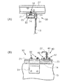
また、この第二の接合板41として、図2A、B及び図4A、Bに示すように、横根太27の側面と縦根太21の上面に面する取付面を有する側面L字形のものを使用してもよい。このとき、この側面L字形の第二の接合板41を横根太27の側面に固定するための手段と第二の接合板41を縦根太21に固定するための手段は、それぞれ、上記の既知の手段から選択でき、この既知の手段により、横根太27の側面と縦根太21の上面に面した第二の接合板41の取付面が横根太27の側面と縦根太21の上面に取り付けられて、第二の接合板41が横根太27の側面と縦根太21の上面に固定される。
Further, as the second joining
好適に、図示のように、縦根太21の上面に、縦根太21の長手方向に長い断面C字形の上面溝25が、さらに形成され(図示の例では、上面溝25が1個形成されているが、図6A〜図6Eに示すように、複数個形成されてもよい)、このとき、横根太27の側面と縦根太21の上面に面する取付面を有する上記の側面L字形の第二の接合板41は、一端がこの上面溝25内に嵌入される第二のボルト手段42(ボルトの頭が上面溝内に嵌入される)によって、縦根太21に固定される。
Preferably, as shown in the drawing, an
ここで、図8に示すように、縦根太21の上面に面する第二の接合板41の取付面の幅は、縦根太21のエッジ部分の傾斜面24の開始点24´と、これと反対側の縦根太21のエッジとの間の距離と同じ、又はこの距離よりも長い。これにより、荷重による第二の接合板41の変形が防止され、また、縦根太21の上面に作用する応力を分散できる。
Here, as shown in FIG. 8, the width of the mounting surface of the second joining
好適に、横根太27として、図2〜図5に示すように、C字形の断面を有するものが使用され、このとき、第二の固定手段40は、この横根太27の下面を縦根太21に固定するための第三のボルト手段43からさらに構成され、この第三のボルト手段43の一端(ボルトの頭)が、縦根太21の上面溝25内に嵌入される。
Preferably, as the
また、縦根太21として、図6A〜図6Eに示すように、中空のものが使用され、このとき、この縦根太21の内部には、図6Eに示すように、縦根太21の内部下面から上面溝25の裏面にわたるリブ26が形成される。これにより、中空の縦根太21が補強される。
Moreover, as shown in FIG. 6A-FIG. 6E, a hollow thing is used as the
10・・・荷箱
11・・・荷台
12・・・床板
13・・・シャーシ
14・・・パッキン材
20・・・トラック荷台下部構造
21・・・縦根太
22・・・下面溝
23・・・側面溝
24・・・傾斜面
24´・・・傾斜面の開始点
25・・・上面溝
26・・・リブ
27・・・横根太
30・・・第一の固定手段
31・・・第一の接合板
32・・・第一のボルト手段
40・・・第二の固定手段
41・・・第二の接合板
42・・・第二のボルト手段
43・・・第三のボルト手段
DESCRIPTION OF
Claims (16)
パッキン材を介して前記シャーシの上面に配置される角筒状の縦根太、
前記縦根太を前記シャーシに固定するための第一の固定手段、
前記縦根太と交差して前記縦根太の上面に配置される角筒状の横根太、及び
前記横根太を前記縦根太に固定するための第二の固定手段、
から成り、
前記縦根太の下面に、前記縦根太の長手方向に長い断面コ字形の下面溝が形成され、この下面溝内に前記パッキン材が配置される、
ところのトラック荷台下部構造。 A truck bed bottom structure for attaching a bed to a truck chassis,
A square tube-shaped vertical joist placed on the upper surface of the chassis via a packing material,
First fixing means for fixing the vertical joists to the chassis;
A rectangular tube-shaped horizontal joist arranged on the upper surface of the vertical joist crossing the vertical joist, and a second fixing means for fixing the horizontal joist to the vertical joist,
Consisting of
A bottom groove having a U-shaped cross section that is long in the longitudinal direction of the vertical joist is formed on the lower surface of the vertical joist, and the packing material is disposed in the lower groove.
However, the lower structure of the truck bed.
前記縦根太の側面に、前記縦根太の長手方向に長い1個又は複数個の断面C字形の側面溝が形成され、
この側面溝を形成した側の前記縦根太の上面のエッジ部分に、下方向に傾斜する傾斜面が形成され、
前記第一の固定手段が、
前記縦根太の側面と前記シャーシの側面に面した取付面を有する第一の接合板、
前記第一の接合板を前記シャーシの側面に固定するための手段、及び
前記第一の接合板を前記縦根太に固定するための第一のボルト手段であって、この第一のボルト手段の一端が、前記側面溝内に嵌入される、ところの第一のボルト手段、
から成り、
前記第二の固定手段が、
第二の接合板、
この第二の接合板を前記横根太の側面に固定するための手段、及び
この第二の接合板を前記縦根太に固定するための手段、
から成る、
ところのトラック荷台下部構造。 The truck bed substructure according to claim 1,
On the side surface of the vertical joist, one or a plurality of side grooves having a C-shaped cross section that are long in the longitudinal direction of the vertical joist are formed,
An inclined surface inclined downward is formed on the edge portion of the upper surface of the vertical joist on the side where the side groove is formed,
The first fixing means is
A first joining plate having a mounting surface facing a side surface of the vertical joist and a side surface of the chassis;
Means for fixing the first joining plate to the side surface of the chassis, and first bolt means for securing the first joining plate to the longitudinal joists, wherein the first bolt means A first bolt means, one end of which is fitted into the side groove,
Consisting of
The second fixing means is
The second joining plate,
Means for fixing the second bonding plate to the side surface of the horizontal joists, and means for fixing the second bonding plate to the vertical joists,
Consisting of,
However, the lower structure of the truck bed.
前記第二の接合板が、前記横根太の側面と前記縦根太の上面に面する取付面を有し、
前記取付面の幅が、前記縦根太の傾斜面の開始点と、これと反対側の前記縦根太のエッジとの間の距離と同じ、又はこの距離よりも長い、
ところのトラック荷台下部構造。 The truck bed substructure according to claim 2,
The second joining plate has a mounting surface facing a side surface of the horizontal joists and an upper surface of the vertical joists,
The width of the mounting surface is the same as or longer than the distance between the starting point of the inclined surface of the vertical joist and the edge of the vertical joist on the opposite side thereof,
However, the lower structure of the truck bed.
前記第二の接合板が、前記横根太の側面と前記縦根太の側面に面する取付面を有し、
前記第二の接合板を前記縦根太に固定するための前記手段が、第二のボルト手段であり、この第二のボルト手段の一端が、前記側面溝内に嵌入される、
ところのトラック荷台下部構造。 The truck bed substructure according to claim 2,
The second joining plate has a mounting surface facing the side surface of the horizontal joist and the side surface of the vertical joist,
The means for fixing the second joining plate to the vertical joists is a second bolt means, and one end of the second bolt means is fitted into the side groove.
However, the lower structure of the truck bed.
前記縦根太の上面に、前記縦根太の長手方向に長い1個又は複数個の断面C字形の上面溝が形成され、
前記第二の接合板が、前記横根太の側面と前記縦根太の上面に面する取付面を有し、
前記第二の接合板を前記縦根太に固定するための前記手段が、第二のボルト手段であり、この第一のボルト手段の一端が、前記上面溝内に嵌入され、
前記縦根太の上面に面する取付面の幅が、前記縦根太の傾斜面の開始点と、これと反対側の前記縦根太のエッジとの間の距離と同じ、又はこの距離よりも長い、
ところのトラック荷台下部構造。 The truck bed substructure according to claim 2,
On the upper surface of the vertical joists, one or a plurality of C-shaped upper surface grooves that are long in the longitudinal direction of the vertical joists are formed,
The second joining plate has a mounting surface facing a side surface of the horizontal joists and an upper surface of the vertical joists,
The means for fixing the second joining plate to the vertical joists is a second bolt means, and one end of the first bolt means is fitted into the upper surface groove,
The width of the mounting surface facing the upper surface of the vertical joist is the same as or longer than the distance between the starting point of the inclined surface of the vertical joist and the edge of the vertical joist on the opposite side,
However, the lower structure of the truck bed.
前記横根太が、C字形の断面を有し、
前記第二の固定手段が、
前記横根太を下面を前記縦根太に固定するための第三のボルト手段であって、前記第三のボルト手段の一端が前記上面溝内に嵌入される、ところの第三のボルト手段、
からさらに成る、
ところのトラック荷台下部構造。 The truck bed substructure according to claim 5,
The lateral joist has a C-shaped cross section,
The second fixing means is
A third bolt means for fixing the horizontal joist to the bottom joist, wherein one end of the third bolt means is fitted into the upper groove;
Further comprising
However, the lower structure of the truck bed.
前記縦根太が、中空であり、
前記縦根太の内部に、前記縦根太の内部下面から前記上面溝の裏面にわたるリブが形成される、
ところのトラック荷台下部構造。 The truck bed substructure according to claim 5,
The vertical joists are hollow,
Inside the vertical joists, ribs extending from the inner lower surface of the vertical joists to the back surface of the upper surface groove are formed.
However, the lower structure of the truck bed.
前記縦根太の上面に、前記縦根太の長手方向に長い1個又は複数個の断面C字形の上面溝が形成され、
前記縦根太の側面に、前記縦根太の長手方向に長い1個又は複数個の断面C字形の側面溝が形成され、
この側面溝を形成した側の前記縦根太の上面のエッジ部分に、下方向に傾斜する傾斜面が形成され、
前記第一の固定手段が、
前記縦根太の上面と前記シャーシの側面に面した取付面を有する第一の接合板、
前記第一の接合板を前記シャーシの側面に固定するための手段、及び
前記第一の接合板を前記縦根太に固定するための第一のボルト手段であって、この第一のボルト手段の一端が、前記上面溝内に嵌入される、ところの第一のボルト手段、
から成り、
前記第二の固定手段が、
第二の接合板、
前記第二の接合板を前記横根太の側面に固定するための手段、及び
前記第二の接合板を前記縦根太に固定するための手段、
から成る、
ところのトラック荷台下部構造。 The truck bed substructure according to claim 1,
On the upper surface of the vertical joists, one or a plurality of C-shaped upper surface grooves that are long in the longitudinal direction of the vertical joists are formed,
On the side surface of the vertical joist, one or a plurality of side grooves having a C-shaped cross section that are long in the longitudinal direction of the vertical joist are formed,
An inclined surface inclined downward is formed on the edge portion of the upper surface of the vertical joist on the side where the side groove is formed,
The first fixing means is
A first joining plate having a mounting surface facing an upper surface of the vertical joists and a side surface of the chassis;
Means for fixing the first joining plate to the side surface of the chassis, and first bolt means for securing the first joining plate to the longitudinal joists, wherein the first bolt means A first bolt means, one end of which is inserted into the upper surface groove,
Consisting of
The second fixing means is
The second joining plate,
Means for fixing the second joining plate to a side surface of the horizontal joist, and means for fixing the second joining plate to the vertical joist,
Consisting of,
However, the lower structure of the truck bed.
前記第二の接合板が、前記横根太の側面と前記縦根太の上面に面する取付面を有し、
前記第二の接合板を前記縦根太に固定するための前記手段が、第二のボルト手段であり、この第一のボルト手段の一端が、前記上面溝内に嵌入され、
前記縦根太の上面に面する取付面の幅が、前記縦根太の傾斜面の開始点と、これと反対側の前記縦根太のエッジとの間の距離と同じ、又はこの距離よりも長い、
ところのトラック荷台下部構造。 The truck bed substructure according to claim 8,
The second joining plate has a mounting surface facing a side surface of the horizontal joists and an upper surface of the vertical joists,
The means for fixing the second joining plate to the vertical joists is a second bolt means, and one end of the first bolt means is fitted into the upper surface groove,
The width of the mounting surface facing the upper surface of the vertical joist is the same as or longer than the distance between the starting point of the inclined surface of the vertical joist and the edge of the vertical joist on the opposite side,
However, the lower structure of the truck bed.
前記第二の接合板が、前記横根太の側面と前記縦根太の側面に面する取付面を有し、
前記第二の接合板を前記縦根太に固定するための前記手段が、第二のボルト手段であり、この第二のボルト手段の一端が、前記側面溝内に嵌入される、
ところのトラック荷台下部構造。 The truck bed substructure according to claim 8,
The second joining plate has a mounting surface facing the side surface of the horizontal joist and the side surface of the vertical joist,
The means for fixing the second joining plate to the vertical joists is a second bolt means, and one end of the second bolt means is fitted into the side groove.
However, the lower structure of the truck bed.
前記横根太が、C字形の断面を有し、
前記第二の固定手段が、
前記横根太を下面を前記縦根太に固定するための第三のボルト手段であって、前記第三のボルト手段の一端が前記上面溝内に嵌入される、ところの第三のボルト手段、
からさらに成る、
ところのトラック荷台下部構造。 The truck bed substructure according to claim 8,
The lateral joist has a C-shaped cross section,
The second fixing means is
A third bolt means for fixing the horizontal joist to the bottom joist, wherein one end of the third bolt means is fitted into the upper groove;
Further comprising
However, the lower structure of the truck bed.
前記縦根太が、中空であり、
前記縦根太の内部に、前記縦根太の内部下面から前記上面溝の裏面にわたるリブが形成される、
ところのトラック荷台下部構造。 The truck bed substructure according to claim 8,
The vertical joists are hollow,
Inside the vertical joists, ribs extending from the inner lower surface of the vertical joists to the back surface of the upper surface groove are formed.
However, the lower structure of the truck bed.
前記傾斜面が、ほぼ真直ぐに下向きに傾斜する、
ところのトラック荷台下部構造。 The truck bed substructure according to claim 2,
The inclined surface is inclined substantially straight downward;
However, the lower structure of the truck bed.
前記傾斜面が、丸く下方へ傾斜する、
ところのトラック荷台下部構造。 The truck bed substructure according to claim 2,
The inclined surface is round and inclined downward;
However, the lower structure of the truck bed.
前記傾斜面が、ほぼ真直ぐに下向きに傾斜する、
ところのトラック荷台下部構造。 The truck bed substructure according to claim 8,
The inclined surface is inclined substantially straight downward;
However, the lower structure of the truck bed.
前記傾斜面が、丸く下方へ傾斜する、
ところのトラック荷台下部構造。 The truck bed substructure according to claim 8,
The inclined surface is round and inclined downward;
However, the lower structure of the truck bed.
Priority Applications (1)
| Application Number | Priority Date | Filing Date | Title |
|---|---|---|---|
| JP2004315663A JP4509738B2 (en) | 2004-10-29 | 2004-10-29 | Lower structure of truck bed |
Applications Claiming Priority (1)
| Application Number | Priority Date | Filing Date | Title |
|---|---|---|---|
| JP2004315663A JP4509738B2 (en) | 2004-10-29 | 2004-10-29 | Lower structure of truck bed |
Publications (2)
| Publication Number | Publication Date |
|---|---|
| JP2006123771A true JP2006123771A (en) | 2006-05-18 |
| JP4509738B2 JP4509738B2 (en) | 2010-07-21 |
Family
ID=36718906
Family Applications (1)
| Application Number | Title | Priority Date | Filing Date |
|---|---|---|---|
| JP2004315663A Expired - Fee Related JP4509738B2 (en) | 2004-10-29 | 2004-10-29 | Lower structure of truck bed |
Country Status (1)
| Country | Link |
|---|---|
| JP (1) | JP4509738B2 (en) |
Cited By (2)
| Publication number | Priority date | Publication date | Assignee | Title |
|---|---|---|---|---|
| JP2010100132A (en) * | 2008-10-22 | 2010-05-06 | Nippon Fruehauf Co Ltd | Lower part structure of cargo bed of truck |
| JP2017165124A (en) * | 2016-03-14 | 2017-09-21 | 株式会社トランテックス | Vertical joist, substructure of truck bed and truck |
Citations (3)
| Publication number | Priority date | Publication date | Assignee | Title |
|---|---|---|---|---|
| JPS5625667U (en) * | 1979-08-07 | 1981-03-09 | ||
| JPS6117892Y2 (en) * | 1979-08-06 | 1986-05-31 | ||
| JPH0733778U (en) * | 1993-12-09 | 1995-06-23 | 株式会社ミカワ東海 | Truck carrier assembly structure |
-
2004
- 2004-10-29 JP JP2004315663A patent/JP4509738B2/en not_active Expired - Fee Related
Patent Citations (3)
| Publication number | Priority date | Publication date | Assignee | Title |
|---|---|---|---|---|
| JPS6117892Y2 (en) * | 1979-08-06 | 1986-05-31 | ||
| JPS5625667U (en) * | 1979-08-07 | 1981-03-09 | ||
| JPH0733778U (en) * | 1993-12-09 | 1995-06-23 | 株式会社ミカワ東海 | Truck carrier assembly structure |
Cited By (2)
| Publication number | Priority date | Publication date | Assignee | Title |
|---|---|---|---|---|
| JP2010100132A (en) * | 2008-10-22 | 2010-05-06 | Nippon Fruehauf Co Ltd | Lower part structure of cargo bed of truck |
| JP2017165124A (en) * | 2016-03-14 | 2017-09-21 | 株式会社トランテックス | Vertical joist, substructure of truck bed and truck |
Also Published As
| Publication number | Publication date |
|---|---|
| JP4509738B2 (en) | 2010-07-21 |
Similar Documents
| Publication | Publication Date | Title |
|---|---|---|
| JP2011084946A (en) | Floor board fixture | |
| JP4509738B2 (en) | Lower structure of truck bed | |
| US1710610A (en) | Portable floor | |
| JP2016216955A (en) | Exterior material mounting structure | |
| JP4308029B2 (en) | Floor board material connecting bracket, floor board material connecting method and floor structure thereof | |
| JP2015059337A (en) | Soundproof wall, and spring metal fitting | |
| JP2014077254A (en) | Structure for attaching acoustical board to concrete wall | |
| JP2008068961A (en) | Splice plate of guide rail for elevator | |
| JP4167609B2 (en) | Hole-down hardware and fixing structure between the hardware and support bolt | |
| JP4860492B2 (en) | Sheet connection method and mounting jig | |
| JP5910881B2 (en) | Constrained vibration damping plate mounting structure | |
| JP6516982B2 (en) | Ceiling fall prevention device | |
| JP6801864B2 (en) | Temporary support member for exterior material | |
| JP4160890B2 (en) | Corrugated board mounting bracket | |
| SE1430100A1 (en) | Fastening system and procedure for such | |
| JP7267534B2 (en) | Member for suppressing settling of piles, structure having footboard member, installation method for structure having footboard member | |
| JP2013189747A (en) | Wall fitting structure | |
| JP7232401B2 (en) | Lower end structure of bearing wall | |
| JP2020156615A (en) | Overturn prevention structure and construction method of the same | |
| KR101762931B1 (en) | Structure of floor board | |
| JP2017179988A (en) | Floor substrate structure for post receiver, and bearing member | |
| JP5735215B2 (en) | Wall panel fixture and partition wall using the same | |
| JP2006219835A (en) | Vibration control wall panel and wall structure | |
| JP2007032272A (en) | Structural material | |
| JP2021171079A (en) | Main rope installation pole for truck |
Legal Events
| Date | Code | Title | Description |
|---|---|---|---|
| A621 | Written request for application examination |
Free format text: JAPANESE INTERMEDIATE CODE: A621 Effective date: 20070524 |
|
| RD04 | Notification of resignation of power of attorney |
Free format text: JAPANESE INTERMEDIATE CODE: A7424 Effective date: 20080331 |
|
| A977 | Report on retrieval |
Free format text: JAPANESE INTERMEDIATE CODE: A971007 Effective date: 20091028 |
|
| A131 | Notification of reasons for refusal |
Free format text: JAPANESE INTERMEDIATE CODE: A131 Effective date: 20091105 |
|
| A521 | Written amendment |
Free format text: JAPANESE INTERMEDIATE CODE: A523 Effective date: 20091222 |
|
| TRDD | Decision of grant or rejection written | ||
| A01 | Written decision to grant a patent or to grant a registration (utility model) |
Free format text: JAPANESE INTERMEDIATE CODE: A01 Effective date: 20100330 |
|
| A01 | Written decision to grant a patent or to grant a registration (utility model) |
Free format text: JAPANESE INTERMEDIATE CODE: A01 |
|
| A61 | First payment of annual fees (during grant procedure) |
Free format text: JAPANESE INTERMEDIATE CODE: A61 Effective date: 20100428 |
|
| FPAY | Renewal fee payment (prs date is renewal date of database) |
Free format text: PAYMENT UNTIL: 20130514 Year of fee payment: 3 |
|
| R150 | Certificate of patent (=grant) or registration of utility model |
Free format text: JAPANESE INTERMEDIATE CODE: R150 |
|
| R250 | Receipt of annual fees |
Free format text: JAPANESE INTERMEDIATE CODE: R250 |
|
| R250 | Receipt of annual fees |
Free format text: JAPANESE INTERMEDIATE CODE: R250 |
|
| LAPS | Cancellation because of no payment of annual fees |