JP2006123773A - Connecting structure of rail member and frame in wing vehicle - Google Patents
Connecting structure of rail member and frame in wing vehicle Download PDFInfo
- Publication number
- JP2006123773A JP2006123773A JP2004315665A JP2004315665A JP2006123773A JP 2006123773 A JP2006123773 A JP 2006123773A JP 2004315665 A JP2004315665 A JP 2004315665A JP 2004315665 A JP2004315665 A JP 2004315665A JP 2006123773 A JP2006123773 A JP 2006123773A
- Authority
- JP
- Japan
- Prior art keywords
- rail member
- wing
- hinge means
- wing hinge
- reinforcing
- Prior art date
- Legal status (The legal status is an assumption and is not a legal conclusion. Google has not performed a legal analysis and makes no representation as to the accuracy of the status listed.)
- Granted
Links
- 230000003014 reinforcing effect Effects 0.000 claims abstract description 41
- 230000002787 reinforcement Effects 0.000 claims abstract description 5
- 230000008878 coupling Effects 0.000 claims description 2
- 238000010168 coupling process Methods 0.000 claims description 2
- 238000005859 coupling reaction Methods 0.000 claims description 2
- 230000002265 prevention Effects 0.000 description 1
Images
Landscapes
- Body Structure For Vehicles (AREA)
Abstract
【課題】ウインク車両において、レール部材と枠との間に生ずる応力を減少させることのできる、連結構造を提供する。
【解決手段】ウイング車両は、前枠および後枠と、前後枠を連結する中空のレール部材と、レール部材を前枠に連結するための第一の連結具と、左右の断面L字形ウイング屋根と、該ウイング屋根の各天井部壁とレール部材とを連結する、レール部材の両側面に取り付けられる複数対のウイングヒンジ手段と、レール部材内で前枠側に配置される第一の補強部材とを有する。第一の連結具に、第一の対のウイングヒンジ手段が取り付けられ、レール部材内に配置される第一の補強部材と、レール部材と、第一の連結具とが第一の固定具により一緒に固定され、レール部材内に配置される第一の補強部材と、レール部材と第二の対のウイングヒンジ手段とが、第二の固定具により一緒に固定される。
【選択図】図5
The present invention provides a connection structure capable of reducing stress generated between a rail member and a frame in a wink vehicle.
A wing vehicle includes a front frame and a rear frame, a hollow rail member that connects the front and rear frames, a first connector for connecting the rail member to the front frame, and left and right cross-sectional L-shaped wing roofs. And a plurality of pairs of wing hinge means attached to both side surfaces of the rail member for connecting each ceiling wall of the wing roof and the rail member, and a first reinforcing member disposed on the front frame side in the rail member And have. A first pair of wing hinge means is attached to the first connector, and the first reinforcing member disposed in the rail member, the rail member, and the first connector are provided by the first fixture. A first reinforcement member secured together and disposed within the rail member, and the rail member and the second pair of wing hinge means are secured together by a second fixture.
[Selection] Figure 5
Description
本発明は、ウイング車両におけるレール部材と断面L字形の屋根との連結構造に関し、特に、車両の走行時に生ずる負荷を軽減し、共振を防止することができる構造に関する。 The present invention relates to a connection structure between a rail member and an L-shaped roof in a wing vehicle, and more particularly to a structure that can reduce a load that occurs when the vehicle travels and prevent resonance.
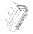
図1は、典型的なウイング車両の後方斜視図を示す。ウイング車両1は、前枠2(図示せず)と後枠3にレール部材4が連結され、天井屋根を構成する天井部壁11とその一端から垂直に伸長する側方屋根を構成する側部壁12から構成される断面がL字形のウイング屋根13、14がレール部材に枢着されている。シリンダー等(図示せず)により、ウイング屋根13、14はレール部材4を中心に回動して、車両の側面全体を開閉することができる。
FIG. 1 shows a rear perspective view of a typical wing vehicle. In the wing vehicle 1, a
従来から、レール部材3と前枠2とを剛直に連結する構造(特許文献1を参照)が採用されてきた。しかし、車両の走行時に生ずる応力のために、連結部に亀裂等が生ずる虞がある。この問題を回避するための連結構造が開発されてきた。この連結構造が図2および3に示されている。
図2、図3に示された従来技術の連結構造では、前枠2に一対の断面L字形のプレート21、22がボルトにより固定されている。そのプレートの間に、レール部材4の先端部が配置され、プレート21、22により支持されるピン23が、レール部材4を貫通している。これにより、レール部材4は、ピン23を中心に回動自在に支持されることになる。
In the connection structure of the prior art shown in FIGS. 2 and 3, a pair of L-
かくして、車両の走行時に生ずる、枠とレール部材とに作用する応力は、吸収され、したがって、応力による亀裂などを回避することができる。ピンによる支持を補強するために、レール部材4内には、補強部材24が配置される(図3Bを参照)。レール部材3には、さらに、ウイング屋根を回動自在支持にするためのウイングヒンジ25が、レール部材3の上面に溶接されている。
Thus, the stress acting on the frame and the rail member, which is generated when the vehicle is running, is absorbed, and therefore cracks due to the stress can be avoided. In order to reinforce the support by the pins, a reinforcing
このようなピン支持は、走行時の応力を吸収することはできるが、レール部材が車体のシャシフレームの振動と共振をおこし、常にピンに応力が作用することには変わりがない。そのため、補強部材24が配置されていても、ピンを支持する部材に力が作用し、亀裂が生ずる虞がある。
Such pin support can absorb the stress at the time of running, but the rail member causes vibration and resonance of the chassis frame of the vehicle body, and the stress always acts on the pin. Therefore, even if the reinforcing
また、レール部材のこのような共振は、L字形屋根13、14にも伝えられ、屋根の開閉不良につながる。さらに、車両の安全な走行が行いにくくなる。
Further, such resonance of the rail member is also transmitted to the L-
そこで、本発明は、レール部材と枠との間に生ずる応力を減少させることのできる、連結構造を提供することを目的とする。 Then, an object of this invention is to provide the connection structure which can reduce the stress which arises between a rail member and a frame.
本発明の他の目的は、レール部材が走行時に車体のシャシフレームと共振することを防止することができる、上記連結構造を提供することである。 Another object of the present invention is to provide the above connection structure that can prevent the rail member from resonating with the chassis frame of the vehicle body during traveling.
上記目的を達成する本発明のウイング車両は、前枠および後枠と、前後枠を連結する中空のレール部材と、レール部材を前枠に連結するための第一の連結具と、天井部壁および該天井部壁の一端から垂直に伸長する側部壁からなる、左右の断面L字形ウイング屋根と、該左右のウイング屋根の各天井部壁の他端とレール部材とを連結する、レール部材の両側面に所定の間隔で取り付けられる複数対のウイングヒンジ手段と、レール部材内で、前枠側に配置される第一の補強部材と、を有し、第一の連結具に、複数対のウイングヒンジ手段のうちの第一の対のウイングヒンジ手段が取り付けられ、レール部材内に配置される第一の補強部材と、レール部材と、第一の連結具とが第一の固定具により一緒に固定され、レール部材内に配置される第一の補強部材と、レール部材と、複数対のウイングヒンジ手段のうちの第二の対のウイングヒンジ手段とが、第二の固定具により一緒に固定される、ことを特徴とする。 The wing vehicle of the present invention that achieves the above object includes a front frame and a rear frame, a hollow rail member that connects the front and rear frames, a first connector for connecting the rail member to the front frame, and a ceiling wall. A rail member that connects the left and right cross-section L-shaped wing roofs, and the other end of each ceiling wall of the left and right wing roofs, and a rail member. A plurality of pairs of wing hinge means attached to both side surfaces of the frame at a predetermined interval, and a first reinforcing member disposed on the front frame side in the rail member. The first pair of wing hinge means of the wing hinge means is attached, and the first reinforcing member disposed in the rail member, the rail member, and the first coupling tool are provided by the first fixing tool. Fixed together and placed in the rail member A reinforcing member, and the rail member, and a second pair of wings hinge means of a plurality of pairs of wings hinge means are secured together by a second fastener, wherein the.
ここで、レール部材内に配置される第一の補強部材と、レール部材と、第一の連結具と、複数対のウイングヒンジ手段のうちの第一の対のウイングヒンジ手段とは第一の固定具により一緒に固定されてもよい。 Here, the first reinforcement member disposed in the rail member, the rail member, the first connector, and the first pair of wing hinge means among the plurality of pairs of wing hinge means are the first You may fix together with a fixing tool.
好適に、第一の補強部材は、少なくとも第一の固定具の固定位置から第二の固定具の固定位置までの長さを有する。 Preferably, the first reinforcing member has at least a length from a fixing position of the first fixing tool to a fixing position of the second fixing tool.
本発明のウイング車両は、レール部材内で、後枠側に配置される第二の補強部材をさらに有することが望ましい。ここで、後枠に取り付けられた第二の連結具により、レール部材は後枠に連結され、第二の連結具に、複数対のウイングヒンジ手段のうちの第三の対のウイングヒンジ手段が取り付けられ、レール部材内に配置される第二の補強部材と、レール部材と、第二の連結具とが第三の固定具により一緒に固定され、レール部材内に配置される第二の補強部材と、レール部材と、複数対のウイングヒンジ手段のうちの第四の対のウイングヒンジ手段とが、第四の固定具により一緒に固定される。 The wing vehicle of the present invention preferably further includes a second reinforcing member disposed on the rear frame side in the rail member. Here, the rail member is connected to the rear frame by the second connector attached to the rear frame, and the third pair of wing hinge means of the plurality of pairs of wing hinge means is connected to the second connector. A second reinforcement member mounted and disposed within the rail member, the rail member, and the second connector are secured together by a third fastener and disposed within the rail member. The member, the rail member, and the fourth pair of wing hinge means of the plurality of pairs of wing hinge means are fixed together by a fourth fixture.
また、レール部材内に配置される第二の補強部材と、レール部材と、第二の連結具と、複数対のウイングヒンジ手段のうちの第三の対のウイングヒンジ手段とは第三の固定具により一緒に固定されてもよい。第二の補強部材は、少なくとも第三の固定具の固定位置から第四の固定具の固定位置までの長さを有することが望ましい。 The second reinforcing member disposed in the rail member, the rail member, the second connector, and the third pair of wing hinge means of the plurality of pairs of wing hinge means are third fixed. It may be fixed together by a tool. The second reinforcing member preferably has a length from at least the fixing position of the third fixing tool to the fixing position of the fourth fixing tool.
中空のレール部材内に、補助部材が配置され、この補強部材と、レール部材と、枠に取り付けられた連結具とが固定具により一緒に固定されることで、さらに補強部材と、レール部材と、ウイングヒンジ手段とが、他の固定具により一緒に固定されることで、レール部材に作用する応力は、補強部材に分散される。 The auxiliary member is disposed in the hollow rail member, and the reinforcing member, the rail member, and the connecting member attached to the frame are fixed together by the fixing member, so that the reinforcing member, the rail member, Since the wing hinge means is fixed together by another fixing tool, the stress acting on the rail member is distributed to the reinforcing member.
さらに、レール部材のうちで、二つの固定具により補強部材が固定された部分では実質的な振動が抑制されるために、レール部材の固有振動数が高くなり、シャシフレームの振動と共振が防止される。 Furthermore, since the substantial vibration is suppressed at the portion of the rail member where the reinforcing member is fixed by the two fixtures, the natural frequency of the rail member is increased and the vibration and resonance of the chassis frame are prevented. Is done.
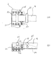
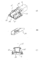
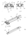
図4Aおよび図4Bは、それぞれ本発明の連結構造の平面および側面を示す。本発明の連結構造において、前枠2の上面に、二つのL字形のプレート41、42がボルトにより固定されている(図4,図5A、図5Cを参照)。これらプレートには、それぞれ、ウイング屋根13、14を回動自在に支持するための所定の間隔で取り付けられる複数対のウイングヒンジのうち、第一のウイングヒンジ43、44が固定されている。このプレートの間に、レール部材4が配置される。
4A and 4B show the plane and side of the connecting structure of the present invention, respectively. In the connection structure of the present invention, two L-
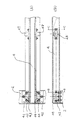
レール部材4は中空体で、その中に補強部材60が配置される。補強部材60は、図5Dに示されているように、その断面面積がレール部材4の断面面積とほぼ一致し、軸線方向を横切る方向の断面がコ字形をし、さらに、以下で説明するように、二つのウイングヒンジの間の距離と同じ長さを少なくとも有し、さらに、二つのウイングヒンジが位置するところに対応して、軸線方向を横切る方向に補強板61、62を有する。これら補強板は、補強部材60が変形することを防止するもので、例示の二つの他に、一つでも、三つ以上であってもよい。また、補強部材に変形が生じないときには、補強板は不要である。
The
レール部材4内に配置された補強部材60と、レール部材4と、L字形プレート41、42とが一緒に、ボルト45、46により固定される(図5Aを参照)。ここで、ウイングヒンジ43、44は、プレート41、42に取り付けられているが、ボルトに45、46によって、一緒にプレート41、42にそれぞれ固定されてもよい。前述したように、このボルトにより固定された位置に、補強板61が設けられている。
The reinforcing
さらに、レール部材4内に配置された補強部材60と、レール部材4と、第二のウイングヒンジ47、48とが一緒に、ボルト49、50により固定される(図5Bを参照)。前述したように、このボルトにより固定された位置に、補強板62が設けられている。
Furthermore, the reinforcing
このように、レール部材4内に配置された補助部材60の前枠側が、前枠2に取り付けられたL字プレート41、42とともにレール部材4にボルト45、46により固定され、さらに、レール部材4内に配置された補助部材60の後枠側が、ウイングヒンジ47、48とともにレール部材4にボルト49、50により固定されることから、前枠とレール部材と作用する応力は、補強部材60全体に分散される。
Thus, the front frame side of the
レール部材は、従来の連結構造では、前枠と後枠に連結されているため(つまり、二つの枠が支点となることから)、車体を構成するシャシフレームの振動と共振していたが、上記にように、補強部材により、レール部材4は、ボルト49,50により固定されるとことまで、前枠2に支持され、振動することができるレール部材の部分が短くなり、したがって固有振動数が高くなる。そのため、レール部材4は、シャシフレームの振動との共振が防止される(シャシフレームは車体の長さであり、この長さに対応した振動数(シャシフレームの固有振動数)をもつが、補強部材により固定されたレール部材の振動することができる長さが、車体の長さより短くなり、そのため振動数が、シャシフレームの固有振動よりも高くなり、シャシフレームとの共振が防止される)。
In the conventional connection structure, the rail member is connected to the front frame and the rear frame (that is, the two frames serve as fulcrums), and thus resonates with the vibration of the chassis frame constituting the vehicle body. As described above, the
本発明の連結構造を、前枠とレール部材の一端との連結をもって説明してきたが、後枠とレール部材の他端との連結においても同様の連結構造をとることができる。この場合、レール部材の固有振動数はさらに高くなり、シャシフレームとの共振の防止がより確かなものとなる。 Although the connection structure of the present invention has been described with the connection between the front frame and one end of the rail member, the same connection structure can be adopted in the connection between the rear frame and the other end of the rail member. In this case, the natural frequency of the rail member is further increased, and the prevention of resonance with the chassis frame is more certain.
4 レール部材
41、42 L字形プレート
43,44 ウイングヒンジ
45、46 ボルト
47,48 ウイングヒンジ
49、50 ボルト
60 補強部材
61、62 補強板
4 Rail member
41, 42 L-shaped plate
43, 44 Wing hinge
45, 46 volts
47, 48 Wing hinge
49, 50 volts
60 Reinforcing member
61, 62 Reinforcement plate
Claims (7)
前記前後枠を連結する中空のレール部材と、
前記レール部材を前記前枠に連結するための第一の連結具と、
天井部壁および該天井部壁の一端から垂直に伸長する側部壁からなる、左右の断面L字形ウイング屋根と、
該左右のウイング屋根の各天井部壁の他端と前記レール部材とを連結する、前記レール部材の両側面に所定の間隔で取り付けられる複数対のウイングヒンジ手段と、
前記レール部材内で、前記前枠側に配置される第一の補強部材と、
を有し、
前記第一の連結具に、前記複数対のウイングヒンジ手段のうちの第一の対のウイングヒンジ手段が取り付けられ、
前記レール部材内に配置される前記第一の補強部材と、前記レール部材と、前記第一の連結具とが第一の固定具により一緒に固定され、
前記レール部材内に配置される前記第一の補強部材と、前記レール部材と、前記複数対のウイングヒンジ手段のうちの第二の対のウイングヒンジ手段とが、第二の固定具により一緒に固定される、
ことを特徴とするウイング車両。 Front and back frames,
A hollow rail member connecting the front and rear frames;
A first connector for connecting the rail member to the front frame;
Left and right cross-sectional L-shaped wing roofs comprising a ceiling wall and side walls extending vertically from one end of the ceiling wall;
A plurality of pairs of wing hinge means that connect the other end of each ceiling wall of the left and right wing roofs and the rail member, and are attached to both side surfaces of the rail member at a predetermined interval;
A first reinforcing member disposed on the front frame side in the rail member;
Have
A first pair of wing hinge means of the plurality of pairs of wing hinge means is attached to the first connector,
The first reinforcing member disposed in the rail member, the rail member, and the first coupling tool are fixed together by a first fixing tool,
The first reinforcement member disposed in the rail member, the rail member, and the second pair of wing hinge means of the plurality of pairs of wing hinge means are joined together by a second fixture. Fixed,
Wing vehicle characterized by that.
前記第二の連結具に、前記複数対のウイングヒンジ手段のうちの第三の対のウイングヒンジ手段が取り付けられ、
前記レール部材内に配置される前記第二の補強部材と、前記レール部材と、前記第二の連結具とが第三の固定具により一緒に固定され、
前記レール部材内に配置される前記第二の補強部材と、前記レール部材と、前記複数対のウイングヒンジ手段のうちの第四の対のウイングヒンジ手段とが、第四の固定具により一緒に固定される、請求項1に記載のウイング車両 A second connector for connecting the rail member to the rear frame; and a second reinforcing member disposed on the rear frame side in the rail member;
A third pair of wing hinge means of the plurality of pairs of wing hinge means is attached to the second connector,
The second reinforcing member disposed in the rail member, the rail member, and the second connecting tool are fixed together by a third fixing tool,
The second reinforcing member disposed in the rail member, the rail member, and a fourth pair of wing hinge means of the plurality of pairs of wing hinge means are joined together by a fourth fixture. The wing vehicle according to claim 1, which is fixed.
前記補強部材内に、軸線方向に垂直な、一つ以上の補強板を有する、
請求項1または4に記載のウイング車両。
The reinforcing member has a U-shaped cross section;
The reinforcing member has one or more reinforcing plates perpendicular to the axial direction.
The wing vehicle according to claim 1 or 4.
Priority Applications (1)
| Application Number | Priority Date | Filing Date | Title |
|---|---|---|---|
| JP2004315665A JP4546216B2 (en) | 2004-10-29 | 2004-10-29 | Connecting structure of rail member and frame in wing vehicle |
Applications Claiming Priority (1)
| Application Number | Priority Date | Filing Date | Title |
|---|---|---|---|
| JP2004315665A JP4546216B2 (en) | 2004-10-29 | 2004-10-29 | Connecting structure of rail member and frame in wing vehicle |
Publications (2)
| Publication Number | Publication Date |
|---|---|
| JP2006123773A true JP2006123773A (en) | 2006-05-18 |
| JP4546216B2 JP4546216B2 (en) | 2010-09-15 |
Family
ID=36718908
Family Applications (1)
| Application Number | Title | Priority Date | Filing Date |
|---|---|---|---|
| JP2004315665A Expired - Lifetime JP4546216B2 (en) | 2004-10-29 | 2004-10-29 | Connecting structure of rail member and frame in wing vehicle |
Country Status (1)
| Country | Link |
|---|---|
| JP (1) | JP4546216B2 (en) |
Citations (3)
| Publication number | Priority date | Publication date | Assignee | Title |
|---|---|---|---|---|
| JPH01107623U (en) * | 1988-01-13 | 1989-07-20 | ||
| JPH06234325A (en) * | 1993-02-10 | 1994-08-23 | Nissan Shatai Co Ltd | Door opening/closing part structure of vehicle body |
| JP2000289658A (en) * | 1999-04-02 | 2000-10-17 | Nippon Fruehauf Co Ltd | Wing vehicle packing box structure |
-
2004
- 2004-10-29 JP JP2004315665A patent/JP4546216B2/en not_active Expired - Lifetime
Patent Citations (3)
| Publication number | Priority date | Publication date | Assignee | Title |
|---|---|---|---|---|
| JPH01107623U (en) * | 1988-01-13 | 1989-07-20 | ||
| JPH06234325A (en) * | 1993-02-10 | 1994-08-23 | Nissan Shatai Co Ltd | Door opening/closing part structure of vehicle body |
| JP2000289658A (en) * | 1999-04-02 | 2000-10-17 | Nippon Fruehauf Co Ltd | Wing vehicle packing box structure |
Also Published As
| Publication number | Publication date |
|---|---|
| JP4546216B2 (en) | 2010-09-15 |
Similar Documents
| Publication | Publication Date | Title |
|---|---|---|
| CN100398377C (en) | rear body structure | |
| TWI485080B (en) | Front part body structure of vehicle | |
| JP4346317B2 (en) | Auto body front structure | |
| JPH0764278B2 (en) | Front body structure of automobile | |
| CN103282264B (en) | Resin roof hoard structure | |
| JP4766517B2 (en) | Automobile undercarriage | |
| KR100392086B1 (en) | Cowl side part T type box structure of vehicle | |
| US6536837B2 (en) | Joint structure of cab mounting portion | |
| JP2015067057A (en) | Vehicular door | |
| JP4546216B2 (en) | Connecting structure of rail member and frame in wing vehicle | |
| CN100411936C (en) | Vehicle rear tray structure | |
| KR101927382B1 (en) | Body frame structure of vehicle | |
| JP2005153820A (en) | Center pillar structure for automobile | |
| JP7339127B2 (en) | rail car | |
| JP4973030B2 (en) | Rear roof rail structure in a back door vehicle | |
| JPH08142911A (en) | Frame structure for low floor bus | |
| JP2006347358A (en) | Railway frame structure | |
| CN100519307C (en) | Rear top girder structure of back door vehicle | |
| JP2004149085A (en) | Rear vehicle body structure | |
| JP2006027553A (en) | Door hinge device and manufacturing method thereof | |
| CN219312863U (en) | Sub vehicle frame subassembly and vehicle | |
| JP2008126982A (en) | Vehicle door structure | |
| JP5066871B2 (en) | Body side structure | |
| JP7790336B2 (en) | Vehicle rear structure | |
| KR100854392B1 (en) | Structure of aluminum end frame of electric car |
Legal Events
| Date | Code | Title | Description |
|---|---|---|---|
| A621 | Written request for application examination |
Free format text: JAPANESE INTERMEDIATE CODE: A621 Effective date: 20070727 |
|
| RD04 | Notification of resignation of power of attorney |
Free format text: JAPANESE INTERMEDIATE CODE: A7424 Effective date: 20080331 |
|
| A977 | Report on retrieval |
Free format text: JAPANESE INTERMEDIATE CODE: A971007 Effective date: 20090819 |
|
| A131 | Notification of reasons for refusal |
Free format text: JAPANESE INTERMEDIATE CODE: A131 Effective date: 20090827 |
|
| A521 | Request for written amendment filed |
Free format text: JAPANESE INTERMEDIATE CODE: A523 Effective date: 20091013 |
|
| A131 | Notification of reasons for refusal |
Free format text: JAPANESE INTERMEDIATE CODE: A131 Effective date: 20100224 |
|
| A521 | Request for written amendment filed |
Free format text: JAPANESE INTERMEDIATE CODE: A523 Effective date: 20100309 |
|
| TRDD | Decision of grant or rejection written | ||
| A01 | Written decision to grant a patent or to grant a registration (utility model) |
Free format text: JAPANESE INTERMEDIATE CODE: A01 Effective date: 20100614 |
|
| A01 | Written decision to grant a patent or to grant a registration (utility model) |
Free format text: JAPANESE INTERMEDIATE CODE: A01 |
|
| A61 | First payment of annual fees (during grant procedure) |
Free format text: JAPANESE INTERMEDIATE CODE: A61 Effective date: 20100701 |
|
| FPAY | Renewal fee payment (event date is renewal date of database) |
Free format text: PAYMENT UNTIL: 20130709 Year of fee payment: 3 |
|
| R150 | Certificate of patent or registration of utility model |
Free format text: JAPANESE INTERMEDIATE CODE: R150 Ref document number: 4546216 Country of ref document: JP Free format text: JAPANESE INTERMEDIATE CODE: R150 |
|
| R250 | Receipt of annual fees |
Free format text: JAPANESE INTERMEDIATE CODE: R250 |
|
| R250 | Receipt of annual fees |
Free format text: JAPANESE INTERMEDIATE CODE: R250 |
|
| R250 | Receipt of annual fees |
Free format text: JAPANESE INTERMEDIATE CODE: R250 |
|
| R250 | Receipt of annual fees |
Free format text: JAPANESE INTERMEDIATE CODE: R250 |
|
| R250 | Receipt of annual fees |
Free format text: JAPANESE INTERMEDIATE CODE: R250 |
|
| R250 | Receipt of annual fees |
Free format text: JAPANESE INTERMEDIATE CODE: R250 |
|
| R250 | Receipt of annual fees |
Free format text: JAPANESE INTERMEDIATE CODE: R250 |
|
| R250 | Receipt of annual fees |
Free format text: JAPANESE INTERMEDIATE CODE: R250 |
|
| R250 | Receipt of annual fees |
Free format text: JAPANESE INTERMEDIATE CODE: R250 |
|
| R250 | Receipt of annual fees |
Free format text: JAPANESE INTERMEDIATE CODE: R250 |
|
| R250 | Receipt of annual fees |
Free format text: JAPANESE INTERMEDIATE CODE: R250 |
|
| R250 | Receipt of annual fees |
Free format text: JAPANESE INTERMEDIATE CODE: R250 |
|
| EXPY | Cancellation because of completion of term |