JP2006138317A - Core assembly and blade assembly using the same, and cooling flow path forming method - Google Patents
Core assembly and blade assembly using the same, and cooling flow path forming method Download PDFInfo
- Publication number
- JP2006138317A JP2006138317A JP2005304222A JP2005304222A JP2006138317A JP 2006138317 A JP2006138317 A JP 2006138317A JP 2005304222 A JP2005304222 A JP 2005304222A JP 2005304222 A JP2005304222 A JP 2005304222A JP 2006138317 A JP2006138317 A JP 2006138317A
- Authority
- JP
- Japan
- Prior art keywords
- core
- collision
- assembly
- flow path
- cooling
- Prior art date
- Legal status (The legal status is an assumption and is not a legal conclusion. Google has not performed a legal analysis and makes no representation as to the accuracy of the status listed.)
- Pending
Links
Images
Classifications
-
- F—MECHANICAL ENGINEERING; LIGHTING; HEATING; WEAPONS; BLASTING
- F02—COMBUSTION ENGINES; HOT-GAS OR COMBUSTION-PRODUCT ENGINE PLANTS
- F02C—GAS-TURBINE PLANTS; AIR INTAKES FOR JET-PROPULSION PLANTS; CONTROLLING FUEL SUPPLY IN AIR-BREATHING JET-PROPULSION PLANTS
- F02C7/00—Features, components parts, details or accessories, not provided for in, or of interest apart form groups F02C1/00 - F02C6/00; Air intakes for jet-propulsion plants
- F02C7/12—Cooling of plants
-
- F—MECHANICAL ENGINEERING; LIGHTING; HEATING; WEAPONS; BLASTING
- F01—MACHINES OR ENGINES IN GENERAL; ENGINE PLANTS IN GENERAL; STEAM ENGINES
- F01D—NON-POSITIVE DISPLACEMENT MACHINES OR ENGINES, e.g. STEAM TURBINES
- F01D5/00—Blades; Blade-carrying members; Heating, heat-insulating, cooling or antivibration means on the blades or the members
- F01D5/12—Blades
- F01D5/14—Form or construction
- F01D5/147—Construction, i.e. structural features, e.g. of weight-saving hollow blades
-
- F—MECHANICAL ENGINEERING; LIGHTING; HEATING; WEAPONS; BLASTING
- F01—MACHINES OR ENGINES IN GENERAL; ENGINE PLANTS IN GENERAL; STEAM ENGINES
- F01D—NON-POSITIVE DISPLACEMENT MACHINES OR ENGINES, e.g. STEAM TURBINES
- F01D5/00—Blades; Blade-carrying members; Heating, heat-insulating, cooling or antivibration means on the blades or the members
- F01D5/12—Blades
- F01D5/14—Form or construction
- F01D5/18—Hollow blades, i.e. blades with cooling or heating channels or cavities; Heating, heat-insulating or cooling means on blades
-
- F—MECHANICAL ENGINEERING; LIGHTING; HEATING; WEAPONS; BLASTING
- F01—MACHINES OR ENGINES IN GENERAL; ENGINE PLANTS IN GENERAL; STEAM ENGINES
- F01D—NON-POSITIVE DISPLACEMENT MACHINES OR ENGINES, e.g. STEAM TURBINES
- F01D5/00—Blades; Blade-carrying members; Heating, heat-insulating, cooling or antivibration means on the blades or the members
- F01D5/12—Blades
- F01D5/14—Form or construction
- F01D5/18—Hollow blades, i.e. blades with cooling or heating channels or cavities; Heating, heat-insulating or cooling means on blades
- F01D5/186—Film cooling
-
- F—MECHANICAL ENGINEERING; LIGHTING; HEATING; WEAPONS; BLASTING
- F01—MACHINES OR ENGINES IN GENERAL; ENGINE PLANTS IN GENERAL; STEAM ENGINES
- F01D—NON-POSITIVE DISPLACEMENT MACHINES OR ENGINES, e.g. STEAM TURBINES
- F01D5/00—Blades; Blade-carrying members; Heating, heat-insulating, cooling or antivibration means on the blades or the members
- F01D5/12—Blades
- F01D5/14—Form or construction
- F01D5/18—Hollow blades, i.e. blades with cooling or heating channels or cavities; Heating, heat-insulating or cooling means on blades
- F01D5/187—Convection cooling
-
- F—MECHANICAL ENGINEERING; LIGHTING; HEATING; WEAPONS; BLASTING
- F05—INDEXING SCHEMES RELATING TO ENGINES OR PUMPS IN VARIOUS SUBCLASSES OF CLASSES F01-F04
- F05D—INDEXING SCHEME FOR ASPECTS RELATING TO NON-POSITIVE-DISPLACEMENT MACHINES OR ENGINES, GAS-TURBINES OR JET-PROPULSION PLANTS
- F05D2230/00—Manufacture
- F05D2230/20—Manufacture essentially without removing material
- F05D2230/21—Manufacture essentially without removing material by casting
-
- F—MECHANICAL ENGINEERING; LIGHTING; HEATING; WEAPONS; BLASTING
- F05—INDEXING SCHEMES RELATING TO ENGINES OR PUMPS IN VARIOUS SUBCLASSES OF CLASSES F01-F04
- F05D—INDEXING SCHEME FOR ASPECTS RELATING TO NON-POSITIVE-DISPLACEMENT MACHINES OR ENGINES, GAS-TURBINES OR JET-PROPULSION PLANTS
- F05D2250/00—Geometry
- F05D2250/10—Two-dimensional
- F05D2250/18—Two-dimensional patterned
- F05D2250/185—Two-dimensional patterned serpentine-like
-
- F—MECHANICAL ENGINEERING; LIGHTING; HEATING; WEAPONS; BLASTING
- F05—INDEXING SCHEMES RELATING TO ENGINES OR PUMPS IN VARIOUS SUBCLASSES OF CLASSES F01-F04
- F05D—INDEXING SCHEME FOR ASPECTS RELATING TO NON-POSITIVE-DISPLACEMENT MACHINES OR ENGINES, GAS-TURBINES OR JET-PROPULSION PLANTS
- F05D2260/00—Function
- F05D2260/20—Heat transfer, e.g. cooling
- F05D2260/201—Heat transfer, e.g. cooling by impingement of a fluid
-
- F—MECHANICAL ENGINEERING; LIGHTING; HEATING; WEAPONS; BLASTING
- F05—INDEXING SCHEMES RELATING TO ENGINES OR PUMPS IN VARIOUS SUBCLASSES OF CLASSES F01-F04
- F05D—INDEXING SCHEME FOR ASPECTS RELATING TO NON-POSITIVE-DISPLACEMENT MACHINES OR ENGINES, GAS-TURBINES OR JET-PROPULSION PLANTS
- F05D2260/00—Function
- F05D2260/20—Heat transfer, e.g. cooling
- F05D2260/202—Heat transfer, e.g. cooling by film cooling
-
- F—MECHANICAL ENGINEERING; LIGHTING; HEATING; WEAPONS; BLASTING
- F05—INDEXING SCHEMES RELATING TO ENGINES OR PUMPS IN VARIOUS SUBCLASSES OF CLASSES F01-F04
- F05D—INDEXING SCHEME FOR ASPECTS RELATING TO NON-POSITIVE-DISPLACEMENT MACHINES OR ENGINES, GAS-TURBINES OR JET-PROPULSION PLANTS
- F05D2260/00—Function
- F05D2260/20—Heat transfer, e.g. cooling
- F05D2260/221—Improvement of heat transfer
- F05D2260/2214—Improvement of heat transfer by increasing the heat transfer surface
- F05D2260/22141—Improvement of heat transfer by increasing the heat transfer surface using fins or ribs
-
- F—MECHANICAL ENGINEERING; LIGHTING; HEATING; WEAPONS; BLASTING
- F28—HEAT EXCHANGE IN GENERAL
- F28F—DETAILS OF HEAT-EXCHANGE AND HEAT-TRANSFER APPARATUS, OF GENERAL APPLICATION
- F28F3/00—Plate-like or laminated elements; Assemblies of plate-like or laminated elements
- F28F3/12—Elements constructed in the shape of a hollow panel, e.g. with channels
-
- Y—GENERAL TAGGING OF NEW TECHNOLOGICAL DEVELOPMENTS; GENERAL TAGGING OF CROSS-SECTIONAL TECHNOLOGIES SPANNING OVER SEVERAL SECTIONS OF THE IPC; TECHNICAL SUBJECTS COVERED BY FORMER USPC CROSS-REFERENCE ART COLLECTIONS [XRACs] AND DIGESTS
- Y10—TECHNICAL SUBJECTS COVERED BY FORMER USPC
- Y10T—TECHNICAL SUBJECTS COVERED BY FORMER US CLASSIFICATION
- Y10T29/00—Metal working
- Y10T29/49—Method of mechanical manufacture
- Y10T29/49316—Impeller making
- Y10T29/49336—Blade making
- Y10T29/49339—Hollow blade
-
- Y—GENERAL TAGGING OF NEW TECHNOLOGICAL DEVELOPMENTS; GENERAL TAGGING OF CROSS-SECTIONAL TECHNOLOGIES SPANNING OVER SEVERAL SECTIONS OF THE IPC; TECHNICAL SUBJECTS COVERED BY FORMER USPC CROSS-REFERENCE ART COLLECTIONS [XRACs] AND DIGESTS
- Y10—TECHNICAL SUBJECTS COVERED BY FORMER USPC
- Y10T—TECHNICAL SUBJECTS COVERED BY FORMER US CLASSIFICATION
- Y10T29/00—Metal working
- Y10T29/49—Method of mechanical manufacture
- Y10T29/49316—Impeller making
- Y10T29/49336—Blade making
- Y10T29/49339—Hollow blade
- Y10T29/49341—Hollow blade with cooling passage
Landscapes
- Engineering & Computer Science (AREA)
- Mechanical Engineering (AREA)
- General Engineering & Computer Science (AREA)
- Chemical & Material Sciences (AREA)
- Combustion & Propulsion (AREA)
- Architecture (AREA)
- Turbine Rotor Nozzle Sealing (AREA)
Abstract
Description
本発明は、一般に、翼用の冷却流路に関する。特に本発明は、翼用の冷却流路を形成するコア組立体に関する。 The present invention generally relates to cooling channels for blades. In particular, the present invention relates to a core assembly that forms a cooling passage for a blade.
米国政府は、米国海軍により発注された契約番号N00019−02−C−3003に基づき、本発明における幾つかの権利を有することができる。 The United States government may have several rights in this invention based on contract number N00019-02-C-3003 ordered by the United States Navy.
一般的に、ガスタービンエンジンは、燃焼ガスの主流からのエネルギーを、圧縮機を回転かつ駆動する機械的エネルギーに変換する複数のタービンブレードを備える。タービンブレードのそれぞれは、主燃焼ガスの流れから圧縮機を駆動するのが望まれる回転エネルギーを発生する翼部を備える。 In general, gas turbine engines include a plurality of turbine blades that convert energy from the mainstream of combustion gases into mechanical energy that rotates and drives the compressor. Each of the turbine blades includes blades that generate rotational energy that is desired to drive the compressor from the main combustion gas stream.
タービンブレード組立体は、ガスタービンエンジンの燃焼器から排気される高温燃焼ガスに曝される。タービンブレード組立体を通して、かつその上に排気される燃焼ガスの温度は、タービンブレード組立体の耐用年数を減少させる恐れがある。この理由のために、それぞれのタービンブレードには、複数の冷却空気流路が設けられる。冷却空気は、タービンブレードのそれぞれを通して送られて、タービンブレードの表面にあるフィルム孔から排気される。タービンブレードの表面にあるフィルム孔の位置は、タービンブレードの表面上の冷却空気の層を生成する。冷却空気は、タービンブレードを高温燃焼ガスから断熱する。タービンブレードを、高温燃焼ガスへの暴露から断熱することにより、タービンブレードの信頼性と耐用年数が大幅に向上する。 The turbine blade assembly is exposed to hot combustion gases exhausted from the combustor of the gas turbine engine. The temperature of the combustion gases exhausted through and onto the turbine blade assembly can reduce the useful life of the turbine blade assembly. For this reason, each turbine blade is provided with a plurality of cooling air passages. Cooling air is sent through each of the turbine blades and exhausted through film holes in the surface of the turbine blade. The location of the film holes on the surface of the turbine blade creates a layer of cooling air on the surface of the turbine blade. The cooling air insulates the turbine blade from the hot combustion gases. Insulating turbine blades from exposure to hot combustion gases significantly improves turbine blade reliability and service life.
一般的に、タービンブレード内の冷却流路は、セラミックコアにより形成され、そのコアには、タービンブレードを形成するのに使用される溶融材料が設けられ、かつその材料で取囲まれる。タービンブレードを形成するのに使用される溶融材料が一旦固化すると、コア材料が取り外される。コア材料が取り外されると、フィルム冷却孔の所要の形状と共に、所要の冷却空気流路が残される。 Generally, the cooling flow path in the turbine blade is formed by a ceramic core that is provided with and surrounded by a molten material used to form the turbine blade. Once the molten material used to form the turbine blade has solidified, the core material is removed. When the core material is removed, the required cooling air flow path is left with the required shape of the film cooling holes.
明白なように、それぞれのタービンブレード組立体は、冷却空気流路の行止まり、または端部を表す。これは、内部側面またはタービンブレードのプラットフォームから流れる冷却空気が、タービンブレードの先端へ向けて半径方向外側に流れるからである。タービンブレードの先端は、締切られて冷却空気流路の端部を形成する。したがって、タービンブレードを通る冷却空気の唯一の出口は、タービンブレード表面とその周辺に配設される複数のフィルム冷却孔を通る。タービンブレードを冷却するフィルム孔の構成と数量は、冷却空気の所要の流量を生成するように決められる。 As will be apparent, each turbine blade assembly represents a dead end or end of the cooling air flow path. This is because the cooling air flowing from the interior side or turbine blade platform flows radially outward toward the tip of the turbine blade. The tip of the turbine blade is cut off to form the end of the cooling air flow path. Thus, the only outlet for cooling air through the turbine blades is through a plurality of film cooling holes disposed on and around the turbine blade surface. The configuration and quantity of film holes that cool the turbine blades are determined to produce the required flow rate of cooling air.
タービンブレードの形状は、タービンブレードの前縁から後縁への断面全体を通して変わる。前縁は、後縁よりもかなり厚いことが最も多い。しかしながら、後縁における冷却の必要性は、前縁よりも大きいことが多いので、冷却流路を後縁に近接して配置する必要がある。明白なように、薄い縁部セクション内の冷却流路は非常に小さい。この小さい冷却流路は、これらの冷却流路を形成するために小さいコア組立体を必要とする。コア組立体のサイズが減少するにつれて、成形作業中の損傷をより受けやすくなる。小さいコア組立体は、タービンブレードの薄い部分における所要の冷却流路を必要とし、かつ製造中の損傷をより受けやすくなる。 The shape of the turbine blade varies throughout the cross-section from the leading edge to the trailing edge of the turbine blade. The leading edge is most often significantly thicker than the trailing edge. However, the need for cooling at the trailing edge is often greater than the leading edge, so the cooling channel must be located close to the trailing edge. As is apparent, the cooling flow path in the thin edge section is very small. This small cooling channel requires a small core assembly to form these cooling channels. As the size of the core assembly decreases, it becomes more susceptible to damage during the molding operation. Small core assemblies require the required cooling flow path in the thin section of the turbine blade and are more susceptible to damage during manufacturing.
したがって、タービンブレード組立体の薄いセクションに小さい冷却空気流路の形成を実現しながら、確実な製造工程結果を得るに足る強固なコア組立体を開発するのが望ましい。 Accordingly, it is desirable to develop a strong core assembly that is sufficient to achieve reliable manufacturing process results while realizing the formation of a small cooling air flow path in the thin section of the turbine blade assembly.
冷却空気流路の構造と構成の他の問題点は、冷却流路の内側面における冷却空気の方向である。一般的に冷却流路は、主コア部から空気を受容する。ついで、タービンブレードの主コア部は、冷却空気源と連通する。したがって冷却空気流路は、主コアに隣接する内面、およびタービンブレードの外側表面に隣接する外面を備える。冷却空気流路内の衝突孔(インピンジメント孔)は、主コアからの空気を冷却空気流路内に、かつその外面に対抗して連通させる。 Another problem with the structure and configuration of the cooling air channel is the direction of the cooling air on the inner surface of the cooling channel. Generally, the cooling channel receives air from the main core portion. The main core portion of the turbine blade is then in communication with a cooling air source. The cooling air flow path thus comprises an inner surface adjacent to the main core and an outer surface adjacent to the outer surface of the turbine blade. The impingement hole (impingement hole) in the cooling air channel allows air from the main core to communicate with the cooling air channel and against the outer surface thereof.
したがって、製造工程中に信頼でき、かつ伝熱能力利用を最大にする所要の冷却空気流特性を提供する、タービンブレード組立体内の冷却空気流路を形成するコア組立体を開発することが望ましい。 Accordingly, it is desirable to develop a core assembly that forms a cooling air flow path within a turbine blade assembly that provides the required cooling air flow characteristics that are reliable and maximize heat transfer capacity utilization during the manufacturing process.
本発明の代表的実施態様は、衝突孔のそれぞれが他の衝突孔の少なくとも一部から隔離される冷却流路を有するタービンブレード組立体を備える。冷却流路内の衝突孔の隔離は、特定の所要の部位への冷却空気流の方向を実現する。さらに、冷却空気流路の形成に利用されるコア組立体は、生産性を強化しかつ向上する一連の構造部材を提供する。 An exemplary embodiment of the present invention comprises a turbine blade assembly having a cooling channel in which each of the impact holes is isolated from at least a portion of the other impact holes. Isolation of the impingement holes in the cooling flow path provides a direction of cooling air flow to a specific required site. Furthermore, the core assembly utilized to form the cooling air flow path provides a series of structural members that enhance and improve productivity.
本発明の一例のタービンブレード組立体には、主コアと連通する冷却空気流路が形成される。ついで主コアが、他のシステムからの冷却空気と連通する。この冷却流路は、互いに隔離された複数の衝突孔を備える独自のコア組立体を用いて形成される。衝突孔のそれぞれを他の衝突孔の少なくとも一部から隔離することにより、衝突孔間の直交流が防止されて、冷却流路の外面に対する冷却空気流が改良される。 In the turbine blade assembly of the example of the present invention, a cooling air flow path communicating with the main core is formed. The main core then communicates with cooling air from other systems. This cooling flow path is formed using a unique core assembly having a plurality of impact holes isolated from each other. By isolating each of the impact holes from at least a portion of the other impact holes, cross flow between the impact holes is prevented and the cooling air flow to the outer surface of the cooling channel is improved.
コア組立体により、冷却流路の構造が得られ、そしてコア組立体は衝突開口部を形成する衝突構造部材を備える。衝突構造部材のそれぞれは、分離構造部材により、他の構造部材の少なくとも幾つかから隔離される。分離構造部材は、衝突開口部を隔離するチャネルを冷却流路内に形成する。コア組立体により形成されるチャネルのそれぞれは、冷却流路の側面において膨張チャンバと連通する。膨張チャンバ内に、フィルム構造部材があり、その構造部材は、冷却空気流路とタービンブレード組立体の外側表面との間にフィルム開口部を生成するために設けられる。 The core assembly provides a cooling channel structure, and the core assembly includes a collision structure member that forms a collision opening. Each of the impinging structural members is isolated from at least some of the other structural members by a separating structural member. The separation structural member forms a channel in the cooling flow path that isolates the collision opening. Each of the channels formed by the core assembly communicates with the expansion chamber on the side of the cooling flow path. Within the expansion chamber is a film structural member that is provided to create a film opening between the cooling air flow path and the outer surface of the turbine blade assembly.
したがって、本発明のタービンブレード組立体は、タービンブレード用の所要の冷却特性を提供する冷却空気流路を備える。 Accordingly, the turbine blade assembly of the present invention comprises a cooling air flow path that provides the required cooling characteristics for the turbine blade.
本発明のこれらと他の特徴は、以下の説明と、および以下に簡単に説明される図面とから最も良く理解できる。 These and other features of the present invention can be best understood from the following description and the drawings that are briefly described below.
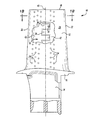
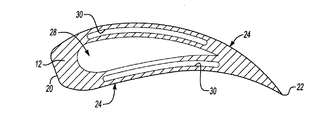
図1Aと1Bを参照すると、タービンブレード組立体10は、翼部12、付根部14、およびプラットフォーム部16を備える。付根部14は、当該技術で知られているように、ハブ部分(図示せず)中に延びる。付根部14は、プラットフォーム部16まで延びる。翼12は、プラットフォーム部16から上方へ延びる。タービン翼部12は、プラットフォーム部16から先端18まで延びる。タービンブレード組立体10は、前縁20と後縁22を備える。前縁20と後縁22との間に、外側表面24がある。外側表面24は、ガス流の流れが機械的回転エネルギーに移行または変換されるように、形状が決められる。理解されるように、タービンブレード組立体10は、図1Aに示されるように、当該技術に有能な者に知られている。この開示で利点を受ける当該技術に有能な者は、種々の用途で利用される他の翼構成についても、本発明の開示と冷却流路とからの利点を得ることが分かるであろう。
Referring to FIGS. 1A and 1B, the
タービンブレード組立体10は、冷却流路30を備える。冷却流路30は、タービンブレード組立体10内に配設される。冷却空気は、付根部14内の流路26を通してタービンブレード組立体10に入る。冷却空気は、流路26を通して主コア28(図1B)に流入する。主コア28は、タービンブレード組立体10の内部における中空部分である。流路26を通して主コア28中に連通する冷却空気は、タービンブレード組立体10内に配設される冷却流路30に入る。冷却空気は、主コア28から複数の衝突開口部32を通して冷却流路30に入る。
The
衝突開口部32からの冷却空気流は、衝突開口部32の反対側に配設される膨張チャンバ42へ向けて流れる。冷却空気流は、タービンブレード組立体10の壁を通り、フィルム開口部34を通して進む。フィルム開口部34を通して冷却流路30から流れ出る冷却空気は、タービンブレード組立体10の外側表面24上を流れて、空気の冷却および断熱の層を形成する。
The cooling air flow from the collision opening 32 flows toward the
本発明のタービンブレード組立体10は、冷却流路30を備える。冷却流路30のそれぞれは、衝突開口部32を備える。衝突開口部32は、チャネル36により互いに隔離される。チャネル36は、一連の分離構造部材38により形成される。衝突開口部32それぞれの分離と絶縁により、冷却流路30の外面に衝突する冷却流の分離が実現できる。さらに、隣接する衝突開口部32の隔離により、典型的な従来技術の衝突開口に生じる直交流の問題が防止され、かつ減少される。衝突開口部32からの流れは、チャネル36を通して、複数のフィルム孔34へ送られる。フィルム孔34は、膨張チャンバ42と連通している。膨張チャンバ42は、冷却流路の一部分を形成して、フィルム孔34へ連通されることになる冷却空気を滞留する。冷却空気を膨張チャンバ42内に滞留することにより、衝突開口部32に対応する壁への逆流衝突に付随する問題が減少される。
The
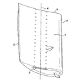
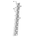
図2を参照すると、翼12の透視図が示されて、主コア28の構成が図示される。主コア28は、タービンブレード組立体10の中央部分を通して上昇しかつ冷却流路30と連通する冷却空気の連通を実現する。図2に図示されるタービンブレード組立体と翼12との特定の形状と構成は、既知の通りである。この開示で利点を受ける者は、多くの種々の型式の翼構成が、この開示内で図示および説明される冷却流路構成から利点を得ることを理解するであろう。
Referring to FIG. 2, a perspective view of the
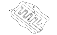
図3を参照すると、冷却流路30は、コア組立体44を用いてタービンブレード組立体10内に形成される。コア組立体44は、タービンブレード組立体10の製作中に、冷却流路の開口部とチャネルを含む種々の構成および構造を実現できる。従来から、タービンブレード組立体10は、従来の成形工程を通して製作されている。コア組立体44は、特別に配合されたセラミックと超硬合金のような既知のコア材料から製作できる。コア組立体44は、モールド内に載置され、ついで、タービンブレード組立体10を構成する溶融材料により取囲まれる。タービンブレード組立体10を形成する材料が固化すると、コア組立体44は、取り外される。コア組立体44の取り外しは、既知の通りであり、かつコア組立体44を破壊し溶出分離するのに薬品が使用される抽出(leeching)または酸化の工程を含む種々の工程から成ることができる。明白なように、この開示で利点を受ける当該技術に有能な者は、既知の他の成形工程および他の材料の使用が本発明の意図と範囲の中に入ることを理解するであろう。タービンブレード組立体10からコア44を取り外すのに利用される取り外し工程の方式は、種々の要因に左右される。これらの要因には、タービンブレード材料の種類、使用されるコア材料の種類、および冷却空気流路の特定の構成がある。
Referring to FIG. 3, the
複雑な冷却空気流路の形成に利用されるコア組立体44は、タービンブレード組立体10内に所望の冷却特性を付与するために必要とされている。コア組立体44は、完成されたタービン組立体10内に延び衝突開口部32を形成する衝突構造部材46を備える。コア組立体44も、衝突開口部32のそれぞれを衝突開口部32の少なくとも他の1つから隔離するのに必要なチャネルおよび壁を形成する分離構造部材48を備える。
A
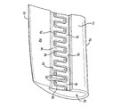
図4を参照すると、翼12が示され、その表面の一部分は、中に形成される冷却空気流路の特定の機能部材を図示するために取り除かれている。冷却空気流路30は、冷却空気流路30の両側に膨張チャンバ42を備える。冷却空気流路30は、前縁側面50と後縁側面52を備える。冷却空気流路30のそれぞれの側面は、膨張チャンバ42を備える。隣接する衝突開口部32は、冷却空気流路30の反対側に配設される膨張チャンバ42と連通する。隣接する2つの衝突開口部は、共通の膨張チャンバ42に冷却空気を流さない。このようにして、特定の空気流を、制御および調整して、翼12の特定の部位と機能部材を冷却できる。
Referring to FIG. 4, a
図5を参照すると、コア組立体44の一例が示され、これは翼12内に衝突開口部32を形成するのに利用される衝突構造部材46を備える。衝突開口部32は、冷却空気を主コア28から冷却流路30中に連通する。コア組立体44はまた、それぞれ隣接する衝突開口部32を通って冷却空気を分離するために使用され、そして提供される分離構造部材48を備える。コア組立体44は、完成したタービンブレード翼12内に形成されるものとは逆の構造を備える。したがって、衝突構造部材46は、翼12を通して延び、かつ主コア28への翼12を通る開口部を形成する伸張部材である。コア組立体44の構造と空間は、完成された翼12内の開放空間を実現する。
Referring to FIG. 5, an example of a
コア組立体44は、複数の伝熱促進機能部材60を備える。これらの伝熱促進機能部材60は、完成された冷却空気流路30内において、伝熱促進機能部材60が、種々の冷却空気流路30内で上方へ延びる複数の隆起部を形成するような開口部として、コア組立体44内に形成される。この開示から利点を得る者は、空気流を中断または送る図示された実施例以外の種々の形状の伝熱促進機能部材60についても、本発明の意図内にあることを理解するであろう。
The
図6を参照すると、外部側面56が図示される。外部側面56は、図4に図示される翼12から切り取られたものである。外部側面56は、図6に示されるように一般的にセクション分けされないが、翼12の一体部分である。外側側面56は、翼12の外側表面に隣接する。図4は、冷却流路30の内部側面54を図示する。内部側面は、主コア28に隣接する。このために、隆起部62が、図6に図示される外部側面56上に設けられる。明白なように、熱エネルギーは、外側表面24に沿って放散する。
Referring to FIG. 6, the
翼12の外側部分に隣接する外部側面56は、その側面上で冷却空気流が、所望の吸熱と伝熱に最も影響を及ぼすように設けられる。衝突開口部32を通る空気流は、衝突開口部32の直ぐ真向かいにある外部側面56に衝突する。ついで空気流は、膨張チャンバ42へ向けて、前縁または後縁へ向けてチャネル36により方向づけられるように進む。チャネル36を通して空気は、制御および調整されて、伝熱と吸熱の特性を向上する乱流作用を生じる。空気は、膨張チャンバ42に一旦達すると、滞留して、フィルム孔34から排気される。ついでフィルム孔34を通して空気は、主燃焼ガス流中に排気される。この実施例のコア組立体44は、ほぼ直線状である。しかしながら、コア組立体44は、特定の翼形状用途に合致するために湾曲した形状を含むことができる。
The
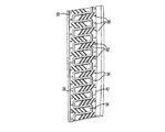
図7を参照すると、冷却空気流路30の外部側面56の形成を実現するコア組立体44の一部分が示される。コア組立体44は、チャネル36、フィルム孔34および分離構造部材38を形成する構造部分を備える。衝突構造部材46は、コア44のこの側面から外方へ延びないことを示すために、破線で図示される。代わりに衝突開口部は、コアの反対側の側面から延びる伸張部材または構造部材46から形成される。コア組立体44のこの側面は、完成された翼12の冷却空気流路30の外部側面56内に、これらの機能部材を生成する。この実施例のコア組立体44において、それぞれの衝突構造部材46は、分離チャネル36中に開放する。したがって、衝突開口部32のそれぞれは、隣接する衝突開口部32のいずれからも隔離される。それぞれのチャネル内には、複数の伝熱促進構造部材60があり、それらの構造部材は、完成されたチャネル36内に所望の隆起部と伝熱隆起部62とを形成する。図7に図示される伝熱構造部材60は、外方へ延びる隆起部を形成するために、成形工程中に材料を受容する空洞である。
Referring to FIG. 7, a portion of the
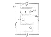
図8を参照すると、コア組立体44の内部側面が示され、その側面は、衝突構造部材46を備える。分離構造部材48は、この側面から延びないが、反対側の側面から延びることを示すために、破線で図示される。さらに、内部側面54から外部側面56上に形成される他の構造部材は、明確にするために示されない。しかしながら明白なように、これらの機能部材は、反対側の側面から外方へ延び、かつこの図面において、破線で表すこともできる。
Referring to FIG. 8, the inner side of the
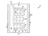
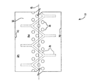
図9と10を参照すると、本発明に従う他の例のコア組立体70が、分離チャネル36内に配設される複数の衝突構造部材46を備える。このコア組立体70において3個の衝突構造部材46が、それぞれの分離チャネル36内に配設される。幾つかの衝突開口部をそれぞれのチャンバ内に設けることにより、特定の空気流必要量および特定の部位上の冷却空気流の衝突を、部位特有の伝熱と吸熱要件に対応するように調整できる。ただし、それぞれのチャネル36内に配設される幾つかの衝突開口部46がある。これらの開口部は、少なくとも1つの他の衝突開口部から隔離され、この他の衝突開口部は少なくとも1つの別の衝突開口部からさらに隔離される。さらに、衝突開口部は全て、中心線40の周りに配設される。
With reference to FIGS. 9 and 10, another
衝突開口部32のそれぞれは、共通の中心線40の周りに配設されるが、少なくとも1つの他の衝突開口部から隔離される。衝突開口部と衝突構造部材46が、中心線40の周りに配設されることが、この例のコア組立体70において示されるが、衝突開口部の他の構成と位置は、本発明の意図内のものである。当該技術に有能な者は、少なくとも1つの衝突開口部の、他の衝突開口部に関しての隔離が、冷却流路における冷却を調整する所望の利点を提供することを理解するであろう。
Each of the impact openings 32 is disposed around a
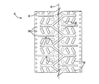
図10を参照すると、図9に示されるものと反対側の側面でのコア組立体が示され、および冷却流路30の外部側面56を形成するコア組立体70の側面が図示される。コア組立体70のこの側面は、完成された翼12におけるフィルム孔34を形成するフィルム構造部材58を図示する。さらに、完成された冷却流路30内に伝熱隆起部64を形成する伝熱構造部材60が図示される。さらに、図示されるように、衝突構造部材46が破線で示されて、外部側面56上に形成される機能部材に関してのそれらの部材の位置が表示される。図10により分かるように、分離構造部材48と伝熱構造部材60は、衝突開口部からフィルム開口部への調整された冷却空気流を生成できる。
Referring to FIG. 10, the core assembly is shown on the side opposite to that shown in FIG. 9, and the side of the
したがって、本発明のコア組立体44と翼12は、タービンブレード組立体10内に冷却空気特性の調整および向上を実現できる。さらに、コア組立体44は、衝突孔開口部のそれぞれを通して空気流を分離するのに望ましい複数の個別チャネルを形成できる単一のコアを備える。衝突開口部のこの隔離は、翼内の局所的な冷却と流れの特性を実現かつ最適化する改良された空気流と調整機能を提供する。
Accordingly, the
本発明の好ましい実施態様を開示してきたが、当該技術に通常の技能を有する者は、幾つかの変更態様が本発明の範囲に入ることを理解するであろう。こうした理由から、本発明の範囲と内容を判断するために、併記の特許請求の範囲を検討すべきである。 While preferred embodiments of the invention have been disclosed, those having ordinary skill in the art will appreciate that several modifications fall within the scope of the invention. For these reasons, the appended claims should be studied to determine the scope and content of the present invention.
10…タービンブレード組立体
12…翼部
14…付根部
16…プラットフォーム
18…先端
20…前縁
22…後縁
24…外側表面
28…主コア
30…冷却流路
32…衝突開口部
34…フィルム開口部
36…チャネル
38…分離構造部材
40…中心線
42…膨張チャンバ
44…コア組立体
46…衝突構造部材
DESCRIPTION OF
Claims (21)
対応する複数の衝突開口部を形成する複数の衝突構造部材を備える第1の側面と、
対応する複数のフィルム開口部を形成する複数のフィルム冷却構造部材を備える第2の側面と、
前記対応する複数の衝突開口部の少なくとも1つを前記対応する複数の衝突開口部の他の1つから分離する壁を形成する複数の分離構造部材と、
を備えるコア組立体。 A core assembly for forming a cooling channel in the blade,
A first side surface comprising a plurality of collision structural members forming a corresponding plurality of collision openings;
A second side surface comprising a plurality of film cooling structural members forming a corresponding plurality of film openings;
A plurality of separating structural members forming a wall separating at least one of the corresponding plurality of collision openings from the other one of the corresponding plurality of collision openings;
A core assembly comprising:
(a)衝突開口部を形成する衝突構造部材、および前記衝突開口部のそれぞれを任意の他の衝突開口部から隔離するチャネルを形成する分離構造部材を備える第1のコアを形成するステップと、
(b)前記翼組立体内に配設されるステップ(a)の前記コアでもって、前記翼組立体を鋳造するステップと、
(c)前記成形された翼を前記コアから取り外すステップと、
を有する方法。 A method of forming a cooling flow path for a blade assembly comprising:
(A) forming a first core comprising a collision structure member forming a collision opening and a separation structure member forming a channel separating each of the collision openings from any other collision opening;
(B) casting the wing assembly with the core of step (a) disposed in the wing assembly;
(C) removing the molded wing from the core;
Having a method.
前記主コアと連通する複数の衝突開口部を備える冷却流路であって、前記複数の衝突開口部の少なくとも1つを前記複数の衝突開口部の他の1つから隔離するチャネルを備える冷却流路と、
を備える翼組立体。 A main core that receives cooling air;
A cooling flow path comprising a plurality of collision openings in communication with the main core, the channel comprising a channel that isolates at least one of the plurality of collision openings from the other one of the plurality of collision openings. Road,
A wing assembly comprising:
Applications Claiming Priority (1)
| Application Number | Priority Date | Filing Date | Title |
|---|---|---|---|
| US10/984,216 US7217095B2 (en) | 2004-11-09 | 2004-11-09 | Heat transferring cooling features for an airfoil |
Publications (1)
| Publication Number | Publication Date |
|---|---|
| JP2006138317A true JP2006138317A (en) | 2006-06-01 |
Family
ID=35478395
Family Applications (1)
| Application Number | Title | Priority Date | Filing Date |
|---|---|---|---|
| JP2005304222A Pending JP2006138317A (en) | 2004-11-09 | 2005-10-19 | Core assembly and blade assembly using the same, and cooling flow path forming method |
Country Status (8)
| Country | Link |
|---|---|
| US (2) | US7217095B2 (en) |
| EP (1) | EP1655452B1 (en) |
| JP (1) | JP2006138317A (en) |
| KR (1) | KR20060049366A (en) |
| CN (1) | CN1773080A (en) |
| CA (1) | CA2523630A1 (en) |
| SG (1) | SG122883A1 (en) |
| TW (1) | TWI279479B (en) |
Cited By (1)
| Publication number | Priority date | Publication date | Assignee | Title |
|---|---|---|---|---|
| JP2013011278A (en) * | 2011-06-29 | 2013-01-17 | Alstom Technology Ltd | Blade used for gas turbine and method for producing such blade |
Families Citing this family (34)
| Publication number | Priority date | Publication date | Assignee | Title |
|---|---|---|---|---|
| US7217095B2 (en) * | 2004-11-09 | 2007-05-15 | United Technologies Corporation | Heat transferring cooling features for an airfoil |
| US7775768B2 (en) * | 2007-03-06 | 2010-08-17 | United Technologies Corporation | Turbine component with axially spaced radially flowing microcircuit cooling channels |
| US8016563B1 (en) * | 2007-12-21 | 2011-09-13 | Florida Turbine Technologies, Inc. | Turbine blade with tip turn cooling |
| US8157527B2 (en) * | 2008-07-03 | 2012-04-17 | United Technologies Corporation | Airfoil with tapered radial cooling passage |
| FR2933884B1 (en) * | 2008-07-16 | 2012-07-27 | Snecma | PROCESS FOR MANUFACTURING AN AUBING PIECE |
| US8572844B2 (en) * | 2008-08-29 | 2013-11-05 | United Technologies Corporation | Airfoil with leading edge cooling passage |
| US8303252B2 (en) * | 2008-10-16 | 2012-11-06 | United Technologies Corporation | Airfoil with cooling passage providing variable heat transfer rate |
| US8109725B2 (en) | 2008-12-15 | 2012-02-07 | United Technologies Corporation | Airfoil with wrapped leading edge cooling passage |
| US8167560B2 (en) * | 2009-03-03 | 2012-05-01 | Siemens Energy, Inc. | Turbine airfoil with an internal cooling system having enhanced vortex forming turbulators |
| US20110110772A1 (en) * | 2009-11-11 | 2011-05-12 | Arrell Douglas J | Turbine Engine Components with Near Surface Cooling Channels and Methods of Making the Same |
| US8511994B2 (en) * | 2009-11-23 | 2013-08-20 | United Technologies Corporation | Serpentine cored airfoil with body microcircuits |
| US8753083B2 (en) * | 2011-01-14 | 2014-06-17 | General Electric Company | Curved cooling passages for a turbine component |
| US8858159B2 (en) * | 2011-10-28 | 2014-10-14 | United Technologies Corporation | Gas turbine engine component having wavy cooling channels with pedestals |
| JP5927893B2 (en) * | 2011-12-15 | 2016-06-01 | 株式会社Ihi | Impinge cooling mechanism, turbine blade and combustor |
| US20130280093A1 (en) * | 2012-04-24 | 2013-10-24 | Mark F. Zelesky | Gas turbine engine core providing exterior airfoil portion |
| US9422817B2 (en) | 2012-05-31 | 2016-08-23 | United Technologies Corporation | Turbine blade root with microcircuit cooling passages |
| DE102012217469A1 (en) * | 2012-09-26 | 2014-03-27 | Siemens Aktiengesellschaft | Cooling system for components in (air) vehicle structures |
| FR3021698B1 (en) | 2014-05-28 | 2021-07-02 | Snecma | TURBINE BLADE, INCLUDING A CENTRAL COOLING DUCT THERMALLY INSULATED FROM THE BLADE WALLS BY TWO JOINT SIDE CAVITIES DOWNSTREAM FROM THE CENTRAL DUCT |
| FR3021699B1 (en) * | 2014-05-28 | 2019-08-16 | Safran Aircraft Engines | OPTIMIZED COOLING TURBINE BLADE AT ITS LEFT EDGE |
| FR3021697B1 (en) * | 2014-05-28 | 2021-09-17 | Snecma | OPTIMIZED COOLING TURBINE BLADE |
| US9988910B2 (en) | 2015-01-30 | 2018-06-05 | United Technologies Corporation | Staggered core printout |
| US9963975B2 (en) | 2015-02-09 | 2018-05-08 | United Technologies Corporation | Trip strip restagger |
| US9995147B2 (en) * | 2015-02-11 | 2018-06-12 | United Technologies Corporation | Blade tip cooling arrangement |
| WO2017103650A1 (en) * | 2015-12-15 | 2017-06-22 | Technion Research & Development Foundation Limited | Acoustic resonance excited heat exchange |
| US10436048B2 (en) | 2016-08-12 | 2019-10-08 | General Electric Comapny | Systems for removing heat from turbine components |
| US10443397B2 (en) | 2016-08-12 | 2019-10-15 | General Electric Company | Impingement system for an airfoil |
| US10408062B2 (en) | 2016-08-12 | 2019-09-10 | General Electric Company | Impingement system for an airfoil |
| US10364685B2 (en) | 2016-08-12 | 2019-07-30 | Gneral Electric Company | Impingement system for an airfoil |
| US10731477B2 (en) * | 2017-09-11 | 2020-08-04 | Raytheon Technologies Corporation | Woven skin cores for turbine airfoils |
| US10759539B2 (en) * | 2018-03-30 | 2020-09-01 | The Boeing Company | Heat exchanger for mitigating ice formation on an aircraft |
| US11339718B2 (en) | 2018-11-09 | 2022-05-24 | Raytheon Technologies Corporation | Minicore cooling passage network having trip strips |
| CN112901278B (en) * | 2021-01-29 | 2022-03-29 | 大连理工大学 | A Turbine Blade Using Snap-Fixed Ceramic Armor |
| CN117262200B (en) * | 2023-10-13 | 2025-08-19 | 哈尔滨工业大学 | Light heat-insulating bearing composite structure for wings and rudder wings |
| CN119160380A (en) * | 2024-11-21 | 2024-12-20 | 中国航空工业集团公司沈阳飞机设计研究所 | A channel actively cooled leading edge structure for high-speed aircraft |
Family Cites Families (18)
| Publication number | Priority date | Publication date | Assignee | Title |
|---|---|---|---|---|
| BE755567A (en) * | 1969-12-01 | 1971-02-15 | Gen Electric | FIXED VANE STRUCTURE, FOR GAS TURBINE ENGINE AND ASSOCIATED TEMPERATURE ADJUSTMENT ARRANGEMENT |
| GB2050918B (en) * | 1979-06-06 | 1982-12-15 | Rolls Royce | Manufacture and inspection of an article |
| GB2105624A (en) * | 1981-09-02 | 1983-03-30 | Rolls Royce | Turbine blade manufacture |
| US4627480A (en) * | 1983-11-07 | 1986-12-09 | General Electric Company | Angled turbulence promoter |
| JPH0756201B2 (en) * | 1984-03-13 | 1995-06-14 | 株式会社東芝 | Gas turbine blades |
| GB2189553B (en) * | 1986-04-25 | 1990-05-23 | Rolls Royce | Cooled vane |
| JPS6380004A (en) | 1986-09-22 | 1988-04-11 | Hitachi Ltd | gas turbine stator blade |
| US5720431A (en) | 1988-08-24 | 1998-02-24 | United Technologies Corporation | Cooled blades for a gas turbine engine |
| US5243759A (en) * | 1991-10-07 | 1993-09-14 | United Technologies Corporation | Method of casting to control the cooling air flow rate of the airfoil trailing edge |
| EP0541207A1 (en) * | 1991-11-04 | 1993-05-12 | General Electric Company | Impingement cooled airfoil with bonding foil insert |
| EP1000225B1 (en) * | 1997-07-29 | 2002-06-05 | Siemens Aktiengesellschaft | Turbine blade and a method for the production thereof |
| US5931638A (en) * | 1997-08-07 | 1999-08-03 | United Technologies Corporation | Turbomachinery airfoil with optimized heat transfer |
| US6174134B1 (en) * | 1999-03-05 | 2001-01-16 | General Electric Company | Multiple impingement airfoil cooling |
| US6179565B1 (en) * | 1999-08-09 | 2001-01-30 | United Technologies Corporation | Coolable airfoil structure |
| DE10001109B4 (en) * | 2000-01-13 | 2012-01-19 | Alstom Technology Ltd. | Cooled shovel for a gas turbine |
| EP1126134A1 (en) * | 2000-02-17 | 2001-08-22 | Siemens Aktiengesellschaft | Air and steam-cooled gas turbine vane |
| EP1136651A1 (en) * | 2000-03-22 | 2001-09-26 | Siemens Aktiengesellschaft | Cooling system for an airfoil |
| US7217095B2 (en) * | 2004-11-09 | 2007-05-15 | United Technologies Corporation | Heat transferring cooling features for an airfoil |
-
2004
- 2004-11-09 US US10/984,216 patent/US7217095B2/en not_active Expired - Lifetime
-
2005
- 2005-10-18 CA CA002523630A patent/CA2523630A1/en not_active Abandoned
- 2005-10-19 JP JP2005304222A patent/JP2006138317A/en active Pending
- 2005-10-19 SG SG200506801A patent/SG122883A1/en unknown
- 2005-10-21 CN CNA2005101283615A patent/CN1773080A/en active Pending
- 2005-10-24 TW TW094137205A patent/TWI279479B/en not_active IP Right Cessation
- 2005-10-26 KR KR1020050101088A patent/KR20060049366A/en not_active Abandoned
- 2005-11-04 EP EP05256849.0A patent/EP1655452B1/en not_active Expired - Lifetime
-
2007
- 2007-05-14 US US11/748,070 patent/US7819169B2/en active Active
Cited By (1)
| Publication number | Priority date | Publication date | Assignee | Title |
|---|---|---|---|---|
| JP2013011278A (en) * | 2011-06-29 | 2013-01-17 | Alstom Technology Ltd | Blade used for gas turbine and method for producing such blade |
Also Published As
| Publication number | Publication date |
|---|---|
| SG122883A1 (en) | 2006-06-29 |
| CN1773080A (en) | 2006-05-17 |
| EP1655452B1 (en) | 2014-04-02 |
| EP1655452A3 (en) | 2009-09-16 |
| US7217095B2 (en) | 2007-05-15 |
| US20080044282A1 (en) | 2008-02-21 |
| CA2523630A1 (en) | 2006-05-09 |
| KR20060049366A (en) | 2006-05-18 |
| EP1655452A2 (en) | 2006-05-10 |
| TW200624656A (en) | 2006-07-16 |
| TWI279479B (en) | 2007-04-21 |
| US7819169B2 (en) | 2010-10-26 |
| US20060096092A1 (en) | 2006-05-11 |
Similar Documents
| Publication | Publication Date | Title |
|---|---|---|
| JP2006138317A (en) | Core assembly and blade assembly using the same, and cooling flow path forming method | |
| EP1010859B1 (en) | Cooling system for a turbine airfoil having a three pass cooling circuit | |
| EP1070829B1 (en) | Internally cooled airfoil | |
| US8414263B1 (en) | Turbine stator vane with near wall integrated micro cooling channels | |
| KR100573658B1 (en) | Turbine elements | |
| JP2862536B2 (en) | Gas turbine blades | |
| US8162609B1 (en) | Turbine airfoil formed as a single piece but with multiple materials | |
| EP3708272B1 (en) | Casting core for a cooling arrangement for a gas turbine component | |
| EP2912274B1 (en) | Cooling arrangement for a gas turbine component | |
| EP1600604B1 (en) | Cooler rotor blade and method for cooling a rotor blade | |
| JP4801513B2 (en) | Cooling circuit for moving wing of turbomachine | |
| CA2462986A1 (en) | Method and apparatus for cooling an airfoil | |
| CN101550843A (en) | Gas turbine airfoil | |
| JPS62159701A (en) | Aerofoil section for turbine of gas turbine engine | |
| JP2005299637A (en) | Method and apparatus for reducing turbine blade temperature | |
| EP1106280B1 (en) | Core to control turbine bucket wall thickness and method | |
| JP2007146841A (en) | Cooling microcircuit for use in turbine engine component, and turbine blade | |
| CN109790754A (en) | Turbine blades including cooling circuit | |
| EP1607578A1 (en) | Cooled rotor blade | |
| US20050169762A1 (en) | Turbine blade for an aircraft engine and casting mold for its manufacture | |
| US6824352B1 (en) | Vane enhanced trailing edge cooling design | |
| GB2366599A (en) | Air-cooled turbine blade | |
| US11885230B2 (en) | Airfoil with internal crossover passages and pin array | |
| JPS59160007A (en) | Stationary blade for gas turbine | |
| JPS59160005A (en) | Stationary blade for gas turbine |
Legal Events
| Date | Code | Title | Description |
|---|---|---|---|
| A131 | Notification of reasons for refusal |
Free format text: JAPANESE INTERMEDIATE CODE: A131 Effective date: 20080408 |
|
| A521 | Request for written amendment filed |
Free format text: JAPANESE INTERMEDIATE CODE: A523 Effective date: 20080701 |
|
| A02 | Decision of refusal |
Free format text: JAPANESE INTERMEDIATE CODE: A02 Effective date: 20090106 |