JP2006144902A - mechanical seal - Google Patents
mechanical seal Download PDFInfo
- Publication number
- JP2006144902A JP2006144902A JP2004335434A JP2004335434A JP2006144902A JP 2006144902 A JP2006144902 A JP 2006144902A JP 2004335434 A JP2004335434 A JP 2004335434A JP 2004335434 A JP2004335434 A JP 2004335434A JP 2006144902 A JP2006144902 A JP 2006144902A
- Authority
- JP
- Japan
- Prior art keywords
- seal
- ring
- stationary
- case
- sealing
- Prior art date
- Legal status (The legal status is an assumption and is not a legal conclusion. Google has not performed a legal analysis and makes no representation as to the accuracy of the status listed.)
- Granted
Links
- 238000007789 sealing Methods 0.000 claims abstract description 112
- 230000002093 peripheral effect Effects 0.000 claims abstract description 38
- 239000011248 coating agent Substances 0.000 claims abstract description 26
- 238000000576 coating method Methods 0.000 claims abstract description 26
- 239000011347 resin Substances 0.000 claims abstract description 26
- 229920005989 resin Polymers 0.000 claims abstract description 26
- 239000002184 metal Substances 0.000 claims abstract description 17
- 239000012530 fluid Substances 0.000 claims description 25
- 238000004891 communication Methods 0.000 claims description 14
- 230000002706 hydrostatic effect Effects 0.000 claims 1
- 239000007789 gas Substances 0.000 description 80
- 230000003068 static effect Effects 0.000 description 40
- 239000004033 plastic Substances 0.000 description 18
- 239000000463 material Substances 0.000 description 9
- 229910021645 metal ion Inorganic materials 0.000 description 8
- 239000000126 substance Substances 0.000 description 7
- 239000002131 composite material Substances 0.000 description 6
- 230000007797 corrosion Effects 0.000 description 6
- 238000005260 corrosion Methods 0.000 description 6
- 229920001343 polytetrafluoroethylene Polymers 0.000 description 6
- 239000004810 polytetrafluoroethylene Substances 0.000 description 6
- 239000000470 constituent Substances 0.000 description 4
- 238000000034 method Methods 0.000 description 4
- 239000000758 substrate Substances 0.000 description 4
- 238000011144 upstream manufacturing Methods 0.000 description 4
- 229920001973 fluoroelastomer Polymers 0.000 description 3
- HBMJWWWQQXIZIP-UHFFFAOYSA-N silicon carbide Chemical compound [Si+]#[C-] HBMJWWWQQXIZIP-UHFFFAOYSA-N 0.000 description 3
- 229910010271 silicon carbide Inorganic materials 0.000 description 3
- OKTJSMMVPCPJKN-UHFFFAOYSA-N Carbon Chemical compound [C] OKTJSMMVPCPJKN-UHFFFAOYSA-N 0.000 description 2
- 229910052799 carbon Inorganic materials 0.000 description 2
- 238000006073 displacement reaction Methods 0.000 description 2
- 229920001971 elastomer Polymers 0.000 description 2
- 235000019000 fluorine Nutrition 0.000 description 2
- 230000001771 impaired effect Effects 0.000 description 2
- 239000007769 metal material Substances 0.000 description 2
- 238000012986 modification Methods 0.000 description 2
- 230000004048 modification Effects 0.000 description 2
- 239000002245 particle Substances 0.000 description 2
- 239000004065 semiconductor Substances 0.000 description 2
- 229910001220 stainless steel Inorganic materials 0.000 description 2
- 239000010935 stainless steel Substances 0.000 description 2
- IJGRMHOSHXDMSA-UHFFFAOYSA-N Atomic nitrogen Chemical compound N#N IJGRMHOSHXDMSA-UHFFFAOYSA-N 0.000 description 1
- YCKRFDGAMUMZLT-UHFFFAOYSA-N Fluorine atom Chemical compound [F] YCKRFDGAMUMZLT-UHFFFAOYSA-N 0.000 description 1
- 229910000831 Steel Inorganic materials 0.000 description 1
- 230000002411 adverse Effects 0.000 description 1
- 230000037237 body shape Effects 0.000 description 1
- 238000001311 chemical methods and process Methods 0.000 description 1
- 238000004140 cleaning Methods 0.000 description 1
- 230000002950 deficient Effects 0.000 description 1
- 229910001873 dinitrogen Inorganic materials 0.000 description 1
- 230000000694 effects Effects 0.000 description 1
- 229910052731 fluorine Inorganic materials 0.000 description 1
- 239000011737 fluorine Substances 0.000 description 1
- 125000001153 fluoro group Chemical group F* 0.000 description 1
- 239000011521 glass Substances 0.000 description 1
- 239000004973 liquid crystal related substance Substances 0.000 description 1
- 238000004519 manufacturing process Methods 0.000 description 1
- -1 polytetrafluoroethylene Polymers 0.000 description 1
- 239000010959 steel Substances 0.000 description 1
Images



Landscapes
- Mechanical Sealing (AREA)
Abstract
Description
本発明は、回転軸側に固定された回転密封環と回転軸が洞貫する金属製のシールケースにOリングを介して軸線方向に移動可能に保持された静止密封環とを具備しており、当該Oリングを静止密封環の周面部に係合保持すると共にシールケースの周面部に押圧接触させることによって、シールケースと静止密封環との間が当該密封環の軸線方向移動を許容しつつ二次シールされるように構成されたメカニカルシールに関するものである。 The present invention includes a rotary seal ring fixed to the rotary shaft side, and a stationary seal ring held in a metal seal case through which the rotary shaft penetrates so as to be movable in the axial direction via an O-ring. The O-ring is engaged and held with the peripheral surface portion of the stationary seal ring and is brought into press contact with the peripheral surface portion of the seal case, thereby allowing the axial movement of the seal ring between the seal case and the stationary seal ring. The present invention relates to a mechanical seal configured to be secondarily sealed.
従来のメカニカルシールとして、回転軸に固定された回転密封環と、回転軸が洞貫するシールケースに一対のOリングを介して軸線方向に移動可能に保持された静止密封環と、静止密封環とシールケースとの間に介装されて、静止密封環を回転密封環へと押圧附勢するスプリングとを具備しており、シールケースと静止密封環との間に当該一対のOリングによりシールされた連通空間を形成すると共に、シールケース及び静止密封環に、当該連通空間を介して連通する一連の通路であって両密封環の対向端面たる密封端面間に開口するシールガス通路を形成して、このシールガス通路から密封端面間に所定圧のシールガスを導入することによって、密封端面間を非接触状態に保持するように構成された静圧形ノンコンタクトガスシールが周知である(例えば、特許文献1参照)。 As a conventional mechanical seal, a rotary seal ring fixed to a rotary shaft, a stationary seal ring held in a seal case through which the rotary shaft passes through a pair of O-rings so as to be movable in the axial direction, and a static seal ring And a spring that presses and urges the stationary sealing ring to the rotating sealing ring, and is sealed by the pair of O-rings between the sealing case and the stationary sealing ring. And a sealing gas passage that is a series of passages communicating with the seal case and the stationary sealing ring through the communication space and that opens between the sealing end faces that are the opposite end faces of the two sealing rings. In addition, a static pressure non-contact gas seal configured to maintain a non-contact state between the sealed end faces by introducing a seal gas having a predetermined pressure between the sealed end faces from the seal gas passage is well known. Some (for example, see Patent Document 1).
ところで、このような静圧形ノンコンタクトガスシールにあっては、シール条件や構造上、前記Oリングを静止密封環の周面部に係合保持させておくことが好ましい場合やそうせざるを得ない場合がある。
しかし、Oリングを静止密封環に係合保持させた場合、静止密封環の軸線方向移動に伴って、Oリングがシールケースの周面部に押圧接触した状態で滑動するため、次のような問題が生じる。 However, when the O-ring is engaged and held with the stationary seal ring, the O-ring slides in a state of being pressed against the peripheral surface portion of the seal case as the stationary seal ring moves in the axial direction. Occurs.
すなわち、シールケースは、その機能上、強度に優れる金属製のものとされることから、Oリングとの接触抵抗が大きく、Oリングの静止密封環に伴う滑動が円滑に行われない。その結果、静止密封環の軸線方向移動が良好に行われず、静止密封環の追従性が低下して、良好なシール機能を発揮できない。特に、上記したような静圧形ノンコンタクトガスシールにあっては、シールガスの供給を停止した場合、静止密封環が回転密封環方向に円滑に移動せず、静止密封環が回転密封環に激しく衝突して、密封端面が損傷,破損する虞れがある。また、逆に、シールガスの供給を停止しても、静止密封環が移動せず、密封端面間に隙間が生じた状態となると、シールガスの供給を再開した場合に、密封端面間にシールガスによる適正な静圧が発生せず、シール機能が喪失する虞れがある。 That is, since the seal case is made of metal having excellent strength in terms of its function, the contact resistance with the O-ring is large, and the sliding with the stationary seal ring of the O-ring is not smoothly performed. As a result, the axial movement of the stationary sealing ring is not performed well, the followability of the stationary sealing ring is lowered, and a satisfactory sealing function cannot be exhibited. In particular, in the static pressure type non-contact gas seal as described above, when the supply of the seal gas is stopped, the stationary seal ring does not move smoothly in the direction of the rotary seal ring, and the static seal ring becomes a rotary seal ring. There is a risk of violent collision and damage or breakage of the sealed end face. Conversely, even if the supply of the sealing gas is stopped, if the stationary sealing ring does not move and there is a gap between the sealing end faces, the seal between the sealing end faces when the supply of the sealing gas is resumed. There is a possibility that the proper static pressure due to the gas is not generated and the sealing function is lost.
このような問題は、両密封環が相対回転摺接することによってシール機能を発揮させる端面接触形のメカニカルシールや密封端面をこの間に動圧を発生させることにより非接触状態に保持するように構成された動圧形の非接触形メカニカルシールにおいても、同様に、生じる。 Such a problem is configured to hold the end face contact type mechanical seal or the sealed end face in a non-contact state by generating dynamic pressure between the two seal rings so that the sealing function is exhibited by the relative rotational sliding contact. This also occurs in the non-contact type mechanical seal of the dynamic pressure type.
本発明は、このような問題を生じることなく、静止密封環の追従性に優れ、良好なシール機能を発揮しうるメカニカルシールを提供することを目的とするものである。 An object of the present invention is to provide a mechanical seal that is excellent in followability of a stationary seal ring and that can exhibit a good sealing function without causing such problems.
本発明は、回転軸側に固定された回転密封環と回転軸が洞貫する金属製のシールケースにOリングを介して軸線方向に移動可能に保持された静止密封環とを具備しており、当該Oリングを静止密封環の周面部に係合保持すると共にシールケースの周面部に押圧接触させることによって、シールケースと静止密封環との間が当該密封環の軸線方向移動を許容しつつ二次シールされるように構成されたメカニカルシールにおいて、上記の目的を達成すべく、特に、シールケースの周面部に、少なくとも静止密封環の軸線方向移動に伴って当該Oリングが相対変位する範囲において、樹脂コーティング膜を形成しておくことを提案する。 The present invention includes a rotary seal ring fixed to the rotary shaft side, and a stationary seal ring held in a metal seal case through which the rotary shaft penetrates so as to be movable in the axial direction via an O-ring. The O-ring is engaged and held with the peripheral surface portion of the stationary seal ring and is brought into press contact with the peripheral surface portion of the seal case, thereby allowing the axial movement of the seal ring between the seal case and the stationary seal ring. In a mechanical seal configured to be secondary-sealed, in order to achieve the above-mentioned object, in particular, a range in which the O-ring is relatively displaced on the peripheral surface portion of the seal case in accordance with at least the axial movement of the stationary seal ring. Then, it is proposed to form a resin coating film.
かかるメカニカルシールは、好ましい実施の形態にあっては、例えば、前記Oリングを所定間隔を隔てて一対設けて、シールケースと静止密封環との間に当該一対のOリングによりシールされた連通空間を形成すると共に、シールケース及び静止密封環に、当該連通空間を介して連通する一連の通路であって両密封環の対向端面たる密封端面間に開口するシールガス通路を形成して、このシールガス通路から密封端面間に所定圧のシールガスを導入することによって、密封端面間を非接触状態に保持するように構成された静圧形ノンコンタクトガスシールとして提案される。 In a preferred embodiment, such a mechanical seal is, for example, a communication space in which a pair of the O-rings are provided at a predetermined interval and sealed by a pair of O-rings between a seal case and a stationary sealing ring. The seal case and the stationary seal ring are formed with a series of passages communicating with each other through the communication space, and a seal gas passage opening between the seal end faces which are the opposite end faces of the seal rings is formed. It is proposed as a static pressure type non-contact gas seal configured to hold a seal gas between a sealed end face in a non-contact state by introducing a seal gas of a predetermined pressure from a gas passage between sealed end faces.
また、被密封流体が金属成分(金属イオン等)の混入を回避すべきものである場合や金属腐食を発生する虞れのあるものである場合にあっては、被密封流体が金属製のシールケースに直接に触れることを防止するために、シールケースにおける周面部であって被密封流体が接触する部分に、当該Oリングが相対変位する部分を含めて、樹脂コーティング膜を形成しておくことが好ましい。特に、上記した静圧形ノンコンタクトガスシールにあっては、被密封流体に加えてシールガスがシールケースに接触することによる金属成分の発生等を防止するために、シールケースにおける周面部及びシールガス通路の内周部であってシールガス及び被密封流体が接触する部分に、当該Oリングが滑動する部分を含めて、樹脂コーティング膜を形成しておくことが好ましい。 If the fluid to be sealed should avoid mixing metal components (metal ions, etc.) or if there is a risk of metal corrosion, the fluid to be sealed should be a metal seal case. In order to prevent direct contact with the seal, a resin coating film may be formed on the peripheral surface portion of the seal case including the portion where the O-ring is relatively displaced at the portion where the fluid to be sealed contacts. preferable. In particular, in the above-described static pressure type non-contact gas seal, in order to prevent the generation of metal components due to the seal gas coming into contact with the seal case in addition to the fluid to be sealed, It is preferable to form a resin coating film on the inner peripheral part of the gas passage, including the part where the O-ring slides, at the part where the sealing gas and the fluid to be sealed contact.
樹脂コーティング膜の構成材としては、Oリングとの接触抵抗が低い低摩擦製のプラスチックを使用することが好ましく、更には、被密封流体の性状やシール条件に応じて耐食性,耐薬品性等の特性に優れたものを使用することが好ましい。一般には、低摩擦性,耐食性等に優れたポリテトラフルオロエチレン(PTEF)等のフッ素樹脂を使用することが好ましい。また、樹脂コーティング膜の膜厚は5〜100μmであることが好ましく、20〜40μmとしておくことが最適する。樹脂コーティング膜の表面(少なくとも当該Oリングが滑動する部分)は、平滑面に機械加工されていることが好ましい。 As a constituent material of the resin coating film, it is preferable to use a low friction plastic having a low contact resistance with the O-ring. Further, depending on the properties of the fluid to be sealed and the sealing conditions, the corrosion resistance, chemical resistance, etc. It is preferable to use one having excellent characteristics. In general, it is preferable to use a fluororesin such as polytetrafluoroethylene (PTEF) having excellent low friction and corrosion resistance. Moreover, it is preferable that the film thickness of a resin coating film is 5-100 micrometers, and it is optimal to set it as 20-40 micrometers. The surface of the resin coating film (at least the portion where the O-ring slides) is preferably machined into a smooth surface.
本発明によれば、静止密封環の移動に伴うOリングのシールケースに対する相対変位が円滑に行われ、静止密封環の追従性に優れたメカニカルシールを提供することができる。したがって、静圧形ノンコンタクトガスシール等のメカニカルシールにあって、静止密封環の追従不良によりシール機能が損なわれるようなことがなく、常に、良好なシール機能を発揮させることができる。また、シールケースにおいて、Oリングとの接触部分を含めて、被密封流体が接触する部分(静圧形ノンコンタクトガスシールにあっては、更にシールガスが接触する部分)を樹脂コーティング膜で被覆しておくことにより、被密封流体及び/又はシールガスが金属製シールケースに接触することによる金属イオンの発生を防止することができ、金属イオンの発生を回避する必要のある条件においても、良好なシール機能を発揮させることができる。また、被密封流体と接触するシールケース部分を耐食性,耐薬品性に優れた樹脂コーティング膜で被覆しておくことにより、被密封流体が腐食性を有するものである場合にも、金属製のシールケースが腐食されるようなことがなく、良好なシール機能を発揮させることができる。 ADVANTAGE OF THE INVENTION According to this invention, the relative displacement with respect to the seal case of O-ring accompanying the movement of a stationary sealing ring is performed smoothly, and the mechanical seal excellent in the followable | trackability of a stationary sealing ring can be provided. Therefore, in a mechanical seal such as a static pressure type non-contact gas seal, the sealing function is not impaired due to the follow-up failure of the stationary sealing ring, and a satisfactory sealing function can always be exhibited. Also, in the seal case, the part that comes into contact with the fluid to be sealed (including the part that comes into contact with the sealing gas in the case of a static pressure type non-contact gas seal), including the part that contacts the O-ring, is covered with a resin coating film. By doing so, it is possible to prevent the generation of metal ions due to the fluid to be sealed and / or the seal gas coming into contact with the metal seal case, and even under conditions where it is necessary to avoid the generation of metal ions. It is possible to exert a proper sealing function. In addition, by covering the seal case part that comes into contact with the sealed fluid with a resin coating film with excellent corrosion resistance and chemical resistance, even if the sealed fluid is corrosive, a metal seal The case is not corroded, and a good sealing function can be exhibited.
図1は本発明に係るメカニカルシール4を装備した処理装置の一例を示す縦断正面図であり、図2はその要部の拡大図である。この処理装置にあっては、回転テーブル1の駆動部2を円筒状のプラスチックカバー3で覆ってあり、半導体ウエハ,電子デバイスの基板,液晶基板,フォトマスク,ガラス基板等の基板を回転テーブル1を使用して適宜の処理(洗浄処理,薬剤処理等)を行う場合に、回転テーブル1が配置された被密封流体領域である処理領域Aと非密封流体領域であるプラスチックカバー3内の領域(カバー内領域(大気領域))Bとをシール装置4により遮蔽シールして、処理領域Aをクリーンに保持するように工夫されている。
FIG. 1 is a longitudinal front view showing an example of a processing apparatus equipped with a
なお、駆動部2は、回転テーブル2に連結されて上下方向に延びる回転軸2a、回転軸2aを回転自在に軸受支持するベアリング、回転軸2aの駆動手段及びこれらをカバー内領域Bにおいて支持する支持機枠2bを具備するものであり、回転テーブル1を回転駆動するように構成されている。回転テーブル1は炭化珪素製のもので、処理領域Aに水平に配置された円板等の回転体形状をなすものである。また、プラスチックカバー3は、図1に示す如く、耐薬品性プラスチック(この例ではPTFEを使用)で一体成形された上端開口状の円筒形状をなすもので、回転テーブル1の下面側に配置される駆動部2を覆っている。回転テーブル1とプラスチックカバー3との間には、必要に応じて、図1に示す如く、適宜のラビリンスシール1aを設けておくことができる。このようなラビリンスシール1aを設けておくことにより、後述するシールガス10のラビリンスシール1aから処理領域Aへの噴出作用と相俟って、薬液等が処理領域Aからカバー内領域Bへの薬液等の侵入を有効に防止することができる。
The
メカニカルシール4は、図1及び図2に示す如く、回転テーブル1にその回転軸線と同心状に固定された回転密封環5と、プラスチックカバー3内に配して駆動部2の支持機枠2bに取り付けられた円筒状のシールケース6と、回転密封環5と同心状をなして回転密封環5に直対向する状態で、シールケース6の内周部6aに一対のOリング12,12を介して軸線方向移動可能に保持された静止密封環7と、シールケース6と静止密封環7との間に介装されて、静止密封環7を回転密封環5へと押圧附勢するスプリング部材8と、プラスチックカバー3の内周部に形成されてシールケース端部6bに衝合する環状のカバー段部3aと、プラスチックカバー3、シールケース6及び静止密封環7を貫通して両密封環5,7の対向端面である密封端面5a,7a間に開口する一連のシールガス通路9と、を具備して、密封端面5a,7a間を、これにシールガス通路9からシールガス10を噴出させることにより、非接触状態に保持しつつ、前記両領域A,B間を遮蔽シールするように構成された静圧形ノンコンタクトガスシールである。
As shown in FIGS. 1 and 2, the
シールケース6は、図1及び図2に示す如く、円筒状の密封環保持部61とその下端部から内方に張り出す円環状のスプリング保持部62とからなる金属製(例えば、SUS316等のステンレス鋼製)のものである。シールケース6は、その下端部(密封環保持部61の下端部)6aをカバー段部3aに衝合させると共にその外周部(密封環保持部61の外周部)をプラスチックカバー3の上端側内周部(カバー段部3aより上方側部分の内周部)にフッ素ゴム製のOリング11を介して密接させた状態で、スプリング保持部62を介して支持機枠2bに取り付けられている。
As shown in FIGS. 1 and 2, the
回転密封環5は、静止密封環7の構成材(例えば、カーボン)より硬質の材料(例えば、炭化珪素)で成形された円環状体であり、図1に示す如く、回転テーブル1の下面部に固定されている。回転密封環5の下端面は、平滑環状面である密封端面(以下「回転側密封端面」ともいう)5aとされている。
The
静止密封環7は、図1に示す如く、上端面を平滑環状面である密封端面(以下「静止側密封端面」ともいう)7aとした円環状体であり、上下方向に並列する一対のフッ素ゴム製のOリング12,12を介してシールケース6の密封環保持部61の内周部6aに軸線方向移動可能(上下方向移動可能)に嵌合保持されている。静止側密封端面7aの外径は回転側密封端面5aの外径より若干小さく設定されており、静止側密封端面7aの内径は回転側密封端面5aの内径より若干大きく設定されている。各Oリング12は、シールケース6の内周部6aに圧接された状態で、静止密封環7の外周部に形成した環状のOリング溝7bに係合保持されていて、静止密封環7の軸線方向移動(上下方向移動)を許容しつつ、静止密封環7とシールケース6との間を二次シールしている。また、静止密封環7の下端部には軸線方向に延びる円形孔7cが形成されており、この円形孔7cにシールケース6のスプリング保持部62に植設した金属製(例えば、SUS316等のステンレス鋼製)のドライブピン13を係合させることにより、静止密封環7を、その軸線方向移動を所定範囲で許容しつつ、シールケース6に対して相対回転不能ならしめている。なお、円形孔7c及びこれに係合するドライブピン13の数は任意であり、必要に応じて複数個設けられる。
As shown in FIG. 1, the
スプリング部材8は、図1に示す如く、静止密封環7とその下位のスプリング保持部62との間に介装された複数個(1個のみ図示)のコイルスプリングで構成されていて、静止密封環7を回転密封環5へと押圧附勢するものであり、密封端面5a,7aを閉じる方向に作用する閉力を発生させるものである。
As shown in FIG. 1, the
シールガス通路9は、図1及び図2に示す如く、プラスチックカバー3に形成されたカバー側通路部分91と、シールケース6に形成されたケース側通路部分92と、静止側密封端面7aに形成された静圧発生溝93と、静止密封環7とシールケース6との対向周面部間に形成され且つOリング12,12によりシールされた環状の連通空間94と、静止密封環7を貫通して連通空間94から静圧発生溝93に至る密封環側通路部分95とからなる。
As shown in FIGS. 1 and 2, the
カバー側通路部分91は、図1に示す如く、プラスチックカバー3を上下方向(プラスチックカバー3の軸線方向)に貫通して、その上端部(下流端)はカバー段部3aに開口されており、その下端部(上流端)は適宜のシールガス供給路(図示せず)に接続されている。
As shown in FIG. 1, the cover-
ケース側通路部分92は、図1に示す如く、シールケース6の密封環保持部61をその下端部から内周部6aへと貫通して、カバー側通路部分91と連通空間94とを連通接続している。ケース側通路部分92の下流端とカバー側通路部分91の上流端との間は、カバー段部3aとシールケース端部6bとの間に介装したフッ素ゴム製のOリング16によりシールされた状態で、連通接続されている。
As shown in FIG. 1, the case
静圧発生溝93は、静止側密封端面7aと同心状の環状をなして連続又は断続する浅い凹溝であり、この例では後者を採用している。すなわち、静圧発生溝93は、図3に示す如く、静止側密封端面7aと同心環状をなして並列する複数の円弧状凹溝93a…で構成されている。連通空間94の上下方向幅(Oリング12,12間の間隔)は、静止密封環7の追従性を確保するために必要とされる軸線方向移動量(上下方向移動量)に応じて設定されており、静止密封環7が移動した場合にも、ケース側通路部分92と連通空間94との接続が解除されないように工夫してある。また、密封環側通路部分95の一端部(上流端)は、Oリング溝7b,7b間において静止密封環7の外周面に開口されており(連通空間94に開口されており)、その他端部(下流端)は複数の分岐部95aに分岐されていて、各分岐部95aを、図3に示す如く、静圧発生溝93を構成する各円弧状凹溝93aに開口させてある。また、シールガス通路9の適所(例えば、密封環側通路95の適所であって分岐部分95aより上流側の部分)には適宜の絞り器96(オリフィス,毛細管,多孔質部材等の絞り機能を有するもの)が配設されていて、密封端面5a,7aの隙間が変動した場合にも、その隙間が自動的に調整されて適正に保持されるように工夫されている。すなわち、回転機器(回転テーブル1)の振動等により密封端面5a,7aの隙間が大きくなったときは、静圧発生溝93から密封端面5a,7a間に流出するシールガス量と絞り器96を通って静圧発生溝93に供給されるシールガス量とが不均衡となり、静圧発生溝93内の圧力が低下して、シールガス10による開力がスプリング部材8による閉力より小さくなるため、密封端面5a,7a間の隙間が小さくなるように変化して、その隙間が適正なものに調整される。逆に、密封端面5a,7a間の隙間が小さくなったときは、上記したと同様の絞り器96による絞り機能により静圧発生溝93内の圧力が上昇して、開力が閉力より大きくなり、密封端面5a,7a間の隙間が大きくなるように変化して、その隙間が適正なものに調整される。
The static
静圧発生溝93には、両領域A,Bより高圧で且つパーティクルを含まない清浄なシールガス10がシールガス通路9(カバー側通路部分91、ケース側通路部分92、連通空間94及び密封環側通路部分95)から供給される。シールガス10としては、各領域A,Bに流出しても何らの悪影響を及ぼさない性状のものを、シール条件に応じて適宜に選定する。この例では、各種物質に対して不活性であり且つ人体に無害である清浄な窒素ガスが使用されている。なお、シールガス10は、一般に、回転テーブル1の運転中(回転軸2aの駆動中)において供給され、運転停止後には供給を停止される。回転テーブル1の運転は、シールガス10の供給が開始された後であって、密封端面5a,7a間が適正な非接触状態に保持された後において開始され、シールガス10の供給停止は、回転テーブルの運転停止後であって回転軸2aが完全に停止した後に行なわれる。なお、必要に応じて、回転テーブル1が運転されていると否とに拘らず、シールガス10の供給を常時、継続して行なうようにすることも可能である。
In the static
シールガス10を静圧発生溝93に供給すると、静圧発生溝93に導入されたシールガス10により、密封端面5a,7a間にこれを開く方向に作用する開力が発生する。この開力は、密封端面5a,7a間に導入されたシールガス10によって発生する静圧によるものである。したがって、密封端面5a,7aは、この開力と密封端面5a,7a間を閉じる方向に作用するスプリング部材8による閉力(スプリング荷重)とがバランスする非接触状態に保持される。すなわち、静圧発生溝93に導入されたシールガス10は密封端面5a,7a間に静圧の流体膜を形成し、この流体膜の存在によって、密封端面5a,7aの外周側領域(処理領域)Aとその内周側領域(カバー内領域)Bとの間が遮蔽シールされる。シールガス10の圧力及びスプリング部材8のバネ力(スプリング荷重)は、密封端面5a,7a間の隙間が適正(一般に、5〜15μmである)となるように、シール条件に応じて適宜に設定される。
When the sealing
ところで、静止密封環7は、シールガス10の供給,停止や絞り器96による隙間調整等によって軸線方向に移動することになり、かかる移動が良好且つ円滑に行われることによって適正なシール機能が発揮される。而して、このような静止密封環7の追従性は、静止密封環7に係合保持されたOリング12,12がシールケース6の内周面6aを円滑に相対変位(滑動)することによって確保されるが、シールケース6が金属製のものであって、その内周面6aとフッ素ゴム等で構成されるOリング12,12との摩擦係数が大きいこと、及びOリング12,12が二次シール機能を発揮すべくシールケース6と静止密封環7との間に圧縮された状態で装填されていて、Oリング12,12がシールケース6の内周面6aに圧接されていること等から、静止密封環7の移動に伴うOリング12,12の変位(滑動)が円滑に行われ難く、静止密封環7の追従性が低下する虞れがある。
By the way, the
そこで、本発明のメカニカルシール4では、図2に示す如く、Oリング12,12が滑動するシールケース部分である密封環保持部61の内周面6aに、低摩擦性の樹脂コーティング膜63を形成して、Oリング12,12の円滑な滑動を可能とし、静止密封環7の追従性を向上させるように図っている。
Therefore, in the
さらに、この例では、樹脂コーティング膜63を、Oリング12,12が接触,滑動するシールケース部分6aのみでなく、被密封流体及びシールガス10が接触するシールケース部分にも形成してある。すなわち、図2に示す如く、シールケース6の密封環保持部61の外表面部分及び密封環側通路部分92の内表面部分に一連の樹脂コーティング膜63を形成して、被密封流体及びシールガス10がシールケース6の金属部分に直接に接触しないように工夫してある。このようにしておくことによって、金属製のシールケース6に被密封流体及びシールガス10が接触することによる金属イオンの発生を防止し、処理領域Aでの処理が金属イオンにより不良となることが防止できる。なお、処理装置及びこれに装備されたメカニカルシール4の構成部材のうち、被密封流体及びシールガス10に接触する部材については、シールケース7を除いて、全て、金属イオンを発生しない非金属材で構成するか非金属材でコーティングしてある。すなわち、回転密封環5を炭化珪素製のものとすると共に静止密封環7をカーボン製のものとし、各Oリング11,12,16をフッ素ゴム製のものとしてある。さらに、回転テーブル1及びカバー3についても、これらをPTFE等の非金属材で構成するか、これらの被処理領域Aに面する部分及びシールガス10に接触する部分をPTFE等で樹脂コーティングしてある。一方、金属で構成されるスプリング部材8やドライブピン13等については、これらをすべてカバー内領域Bに配置してある。したがって、被処理物が半導体ウエハ等の金属イオンを嫌うものである場合にも、その処理を良好に行なうことができる。
Further, in this example, the
ところで、樹脂コーティング膜63の構成材としては、Oリング12との摩擦係数が小さなフッ素樹脂等の低摩擦性プラスチックを使用することが好ましく、この例では、PTFEを使用している。
By the way, as a constituent material of the
また、樹脂コーティング膜63の膜厚は5〜100μmとしておくことが好ましく、20〜40μmとしておくことが最適する。このような膜厚としておくことにより、膜厚のバラツキをなくして均一な膜厚を得ることができ、Oリング12,12との接触抵抗におけるバラツキを回避して、静止密封環7の追従性を大幅に向上させることができる。更に、樹脂コーティング膜63の表面、特に、Oリング12,12が接触する部分63aの表面については、高精度の平滑面に機械加工しておくことが好ましい。
The thickness of the
ところで、上記のメカニカルシール4にあっては、カバー側通路部分91からケース側通路部分92へのガス流動がプラスチックカバー3の軸線方向において行われるように工夫されているから、プラスチックカバー3の材質や肉厚(径方向の厚み)に拘わらず、シールガス10の圧力によってプラスチックカバー3が径方向に変形することがない。したがって、プラスチックカバー3の材質,形状(肉厚)を、シールガス10の圧力に対する強度を考慮することなく、処理装置の使用条件に応じて自由に設定することができる。また、当該カバー3と回転テーブル1との間に前記したようなラビリンスシール1aを設ける場合にも、プラスチックカバー3が変形しないことから、当該ラビリンスシール1aの機能を損なうようなことがない。
By the way, the
なお、本発明の構成は、上記した実施の形態に限定されるものでなく、本発明の基本原理を逸脱しない範囲において、適宜に改良,変更することができる。 The configuration of the present invention is not limited to the above-described embodiment, and can be appropriately improved and changed without departing from the basic principle of the present invention.
本発明は、両密封環が相対回転摺接する端面接触形のメカニカルシールにも適用することができる。しかし、本発明は、静止密封環の追従性が重視される非接触形メカニカルシール(上記した静圧形ノンコンタクトガスシールや一方の密封端面に動圧発生溝を形成して密封端面間をこれに発生させた動圧により非接触状態に保持するように構成された動圧形の非接触形メカニカルシール)において、より好適に適用することができる。 The present invention can also be applied to an end surface contact type mechanical seal in which both sealing rings are in relative rotational sliding contact. However, according to the present invention, a non-contact type mechanical seal in which followability of a stationary seal ring is important (such as the above-described static pressure type non-contact gas seal or a dynamic pressure generating groove formed on one sealed end surface to form a gap between the sealed end surfaces is described. It can be more suitably applied to a dynamic pressure type non-contact type mechanical seal configured to be held in a non-contact state by the generated dynamic pressure.
また、上記したメカニカルシールにあっては、シールガス10による静圧のみによって密封端面5a,7a間を非接触状態に保持する静圧形ノンコンタクトガスシール4に構成したが、図4に示す如く、密封端面5a,7aをこの間に静圧に加えて動圧を発生させることにより非接触状態に保持する複合形ノンコンタクトガスシール104に構成して、本発明を適用するようにすることも可能である。かかる複合形ノンコンタクトガスシールにおいては、シール機能上、静止密封環7の追従性の良否が更に重要な要素となる。
Further, the above-described mechanical seal is configured as a static pressure type
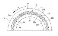
すなわち、図4に示す複合形ノンコンタクトガスシール104にあっては、一方の密封端面である回転密封環5の密封端面(回転側密封端面)5aに動圧発生溝19を形成して、この動圧発生溝19により密封端面5a,7a間に動圧を発生させるように構成してある。動圧発生溝19の形状は、シール条件等に応じて適宜に設定することができるが、この例では、動圧発生溝19を、図6又は図7に示す如く、回転側密封端面5aにおける静圧発生溝93に対向する部位から外径方向であって且つ回転密封環5の回転方向(イ方向)と逆方向に傾斜状に延びる第1グルーブ部分20aと内径方向且つ回転密封環5の回転方向(イ方向)と逆方向に傾斜状に延びる第2グルーブ部分20bとからなる複数のグルーブ20が密封端面5aの周方向に並列してなる形状に構成してある。各グルーブ20は1〜10μmの浅い深さ一定の溝であり、その最外径側端部(第1グルーブ部分20aの外径側端部)及び最内径側端部(第2グルーブ部分20bの内径側端部)は、両密封端面5a,7aの重合領域内に位置されている。すなわち、図5に示す如く、動圧発生溝19の内外径E,Fは、静止密封環7の密封端面(静止側密封端面)7aの外径(≦回転側密封端面5aの外径)A及びその内径(≧回転側密封端面5aの内径)D並びに静圧発生溝93(円弧状凹溝93a)の外径B及びその内径Cに対して、B<F<A,D<E<Cの関係を有する範囲で適宜に設定されている。この例では、0.5≦(F−B)/(A−B)≦0.9又は0.5≦(C−E)/(C−BD)≦0.9の条件を満足するように設定されている。各グルーブ20は、図6に示す如く、第1グルーブ部分20aと第2グルーブ部分20bとが基端部で一致する略く字状をなすものとするか、図7に示す如く、第1グルーブ部分20aと第2グルーブ部分20bとの基端部が周方向に齟齬する千鳥形状をなすものとされる。なお、この複合形ノンコンタクトガスシール104における上記以外の構成は、図1〜図3に示す静圧形ノンコンタクトガスシール4と同一である。
That is, in the composite
このような複合形ノンコンタクトガスシール104によれば、密封端面5a,7a間にシールガス10による静圧に加えて動圧発生溝19による動圧が発生し、これらの静圧及び動圧により密封端面5a,7a間を非接触状態に保持する。したがって、シールガス10による静圧によっては密封端面5a,7aを適正な非接触状態に保持し得ない事態が発生したときにも、動圧によって適正な非接触状態を維持することができる。また、静圧のみで非接触状態に保持する静圧形ノンコンタクトガスシールに比して、シールガス10による静圧によってシールガス10の必要供給量を少なくすることができる。また、動圧発生溝19を密封端面5a,7aの重複領域外に開放されていないため、各グルーブ20の最内径側端部及び最外径側端部が、密封端面5a,7a間に導入されたシールガス10に対する堰として機能することになると共に、密封端面5a,7a間に形成される漏れ間隙を狭めるように作用することになる。その結果、密封端面5a,7a間に導入されたシールガス10の処理領域(被密封ガス領域)A側への漏れ量が抑制されて動圧発生溝19によるシールガス10の捕捉特性が極めて良好なものになる。したがって、シールガス10の消費量を低減でき、万一シールガス10に同伴されるパーティクルがある場合にも、その侵入を極力抑制することができる。なお、複合形ノンコンタクトガスシール104を装備する処理装置の構成,使用条件等によっては、回転テーブル1ないし回転軸2aが一方向でなく両方向に回転される場合があるが、かかる場合には、上記動圧発生溝19を回転密封環5が正転方向及び逆転方向の何れの方向に回転しても動圧を発生しうるような形状としておけばよい。このような動圧発生溝19の形状については、シール条件等に応じて任意に設定することができ、従来からも種々の形状が提案されている。例えば、回転側密封端面5aに、径方向に縦列し且つ直径線に対して対称形状をなす第1動圧発生溝と第2動圧発生溝とからなる動圧発生溝ユニットを周方向に所定間隔を隔てて複数組並列状に形成して、回転密封環5が正転方向に回転するときには第1動圧発生溝により動圧が発生せしめられ、また回転密封環5が逆転方向に回転するときには第2動圧発生溝により動圧が発生せしめられるように構成しておくのである。各第1及び第2動圧発生溝としては、例えば、溝深さ及び溝幅を一定とするL字形溝等を採用することができる。
According to such a composite
また、樹脂コーティング膜63は、金属イオンの発生を抑制する必要のないシール条件下においては、シールケース6におけるOリング12の接触部分であって当該Oリング12が静止密封環7の移動に伴って相対変位(滑動)する部分6aのみに形成しておけばよい。また、樹脂コーティング膜63の材質は、Oリング12との接触抵抗を低減させるものであることを条件として、被密封流体の性状やシール条件に応じて適宜に選定される。例えば、被密封流体がシールケース6を腐食させる虞れのある場合には、シールケース6における被密封流体との接触部分に耐食性,耐薬品性を有する材質の樹脂コーティング膜63を形成しておく。この場合、シールケース6以外のメカニカルシール構成部材又はその部分であって被密封流体に接触する部材又は部分は、耐食性,耐薬品性を有する材質で構成するか又はかかる材質のコーティングを施しておく。このようにすれば、被密封流体が腐食性を有するものである場合にも、良好なシール機能を発揮させることができる。
In addition, the
2a 回転軸
4 メカニカルシール(静圧形ノンコンタクトガスシール)
5 回転密封環
5a 回転密封環の密封端面
6 シールケース
6a シールケースの内周面
7 静止密封環
7a 静止密封環の密封端面
7b Oリング溝
8 スプリング部材
9 シールガス通路
10 シールガス
12 Oリング
61 密封環保持部
63 樹脂コーティング膜
92 ケース側通路部分
93 静圧発生溝
94 連通空間
95 密封環側通路部分
DESCRIPTION OF
Claims (7)
シールケースの周面部に、少なくとも静止密封環の軸線方向移動に伴って当該Oリングが相対変位する範囲において、樹脂コーティング膜を形成してあることを特徴とするメカニカルシール。 A rotary seal ring fixed to the rotary shaft side, and a stationary seal ring held in a metal seal case through which the rotary shaft penetrates so as to be movable in the axial direction via the O-ring. Is engaged with and held in contact with the peripheral surface portion of the stationary seal ring and pressed against the peripheral surface portion of the seal case, so that the seal case and the stationary seal ring are secondarily sealed while allowing the axial movement of the seal ring. In a mechanical seal configured to
A mechanical seal characterized in that a resin coating film is formed on a peripheral surface portion of a seal case at least in a range in which the O-ring is relatively displaced as the stationary seal ring moves in the axial direction.
Priority Applications (7)
| Application Number | Priority Date | Filing Date | Title |
|---|---|---|---|
| JP2004335434A JP4336295B2 (en) | 2004-11-19 | 2004-11-19 | Hydrostatic non-contact gas seal |
| KR1020067002756A KR100711114B1 (en) | 2004-07-02 | 2005-07-01 | Mechanical Seal |
| PCT/JP2005/012225 WO2006004052A1 (en) | 2004-07-02 | 2005-07-01 | Mechanical seal |
| DE602005025776T DE602005025776D1 (en) | 2004-07-02 | 2005-07-01 | MECHANICAL SEAL |
| US11/631,045 US7883093B2 (en) | 2004-07-02 | 2005-07-01 | Mechanical seal |
| EP05765272A EP1780450B1 (en) | 2004-07-02 | 2005-07-01 | Mechanical seal |
| TW94128928A TWI269847B (en) | 2004-11-19 | 2005-08-24 | Mechanical seal |
Applications Claiming Priority (1)
| Application Number | Priority Date | Filing Date | Title |
|---|---|---|---|
| JP2004335434A JP4336295B2 (en) | 2004-11-19 | 2004-11-19 | Hydrostatic non-contact gas seal |
Publications (2)
| Publication Number | Publication Date |
|---|---|
| JP2006144902A true JP2006144902A (en) | 2006-06-08 |
| JP4336295B2 JP4336295B2 (en) | 2009-09-30 |
Family
ID=36624829
Family Applications (1)
| Application Number | Title | Priority Date | Filing Date |
|---|---|---|---|
| JP2004335434A Expired - Lifetime JP4336295B2 (en) | 2004-07-02 | 2004-11-19 | Hydrostatic non-contact gas seal |
Country Status (2)
| Country | Link |
|---|---|
| JP (1) | JP4336295B2 (en) |
| TW (1) | TWI269847B (en) |
Cited By (4)
| Publication number | Priority date | Publication date | Assignee | Title |
|---|---|---|---|---|
| JP2008038938A (en) * | 2006-08-02 | 2008-02-21 | Nippon Pillar Packing Co Ltd | Hydrostatic non-contact gas seal |
| JP2010533827A (en) * | 2007-07-16 | 2010-10-28 | テナリス・コネクシヨンズ・アクチエンゲゼルシヤフト | Screw joint with elastic seal ring |
| JP2016166622A (en) * | 2015-03-09 | 2016-09-15 | 日本ピラー工業株式会社 | End contact type mechanical seal |
| JP2022101151A (en) * | 2020-12-24 | 2022-07-06 | イーグル工業株式会社 | mechanical seal |
Families Citing this family (2)
| Publication number | Priority date | Publication date | Assignee | Title |
|---|---|---|---|---|
| WO2018157910A1 (en) | 2017-02-28 | 2018-09-07 | Harmonic Drive Ag | Strain wave gear mechanism with an inner seal |
| CN118919433A (en) * | 2024-07-18 | 2024-11-08 | 华天科技(昆山)电子有限公司 | System and method for optimizing aperture of wafer level packaging die |
Citations (7)
| Publication number | Priority date | Publication date | Assignee | Title |
|---|---|---|---|---|
| JPH08296744A (en) * | 1995-04-26 | 1996-11-12 | Mitsubishi Heavy Ind Ltd | Mechanical seal |
| WO1999027281A1 (en) * | 1997-11-21 | 1999-06-03 | Nippon Pillar Packing Co., Ltd. | Static pressure noncontact gas seal |
| JP2000331938A (en) * | 1999-05-17 | 2000-11-30 | Applied Materials Inc | Semiconductor manufacturing equipment |
| JP2001200848A (en) * | 2000-01-17 | 2001-07-27 | Matsushita Electric Ind Co Ltd | Fluid bearing device |
| JP2002299271A (en) * | 2001-03-29 | 2002-10-11 | Tokyo Electron Ltd | Vertical heat treatment equipment |
| JP2003148389A (en) * | 2001-11-16 | 2003-05-21 | Boc Edwards Technologies Ltd | Vacuum pump |
| JP2004225725A (en) * | 2003-01-20 | 2004-08-12 | Eagle Ind Co Ltd | Sliding parts |
-
2004
- 2004-11-19 JP JP2004335434A patent/JP4336295B2/en not_active Expired - Lifetime
-
2005
- 2005-08-24 TW TW94128928A patent/TWI269847B/en not_active IP Right Cessation
Patent Citations (7)
| Publication number | Priority date | Publication date | Assignee | Title |
|---|---|---|---|---|
| JPH08296744A (en) * | 1995-04-26 | 1996-11-12 | Mitsubishi Heavy Ind Ltd | Mechanical seal |
| WO1999027281A1 (en) * | 1997-11-21 | 1999-06-03 | Nippon Pillar Packing Co., Ltd. | Static pressure noncontact gas seal |
| JP2000331938A (en) * | 1999-05-17 | 2000-11-30 | Applied Materials Inc | Semiconductor manufacturing equipment |
| JP2001200848A (en) * | 2000-01-17 | 2001-07-27 | Matsushita Electric Ind Co Ltd | Fluid bearing device |
| JP2002299271A (en) * | 2001-03-29 | 2002-10-11 | Tokyo Electron Ltd | Vertical heat treatment equipment |
| JP2003148389A (en) * | 2001-11-16 | 2003-05-21 | Boc Edwards Technologies Ltd | Vacuum pump |
| JP2004225725A (en) * | 2003-01-20 | 2004-08-12 | Eagle Ind Co Ltd | Sliding parts |
Cited By (6)
| Publication number | Priority date | Publication date | Assignee | Title |
|---|---|---|---|---|
| JP2008038938A (en) * | 2006-08-02 | 2008-02-21 | Nippon Pillar Packing Co Ltd | Hydrostatic non-contact gas seal |
| JP2010533827A (en) * | 2007-07-16 | 2010-10-28 | テナリス・コネクシヨンズ・アクチエンゲゼルシヤフト | Screw joint with elastic seal ring |
| US9383045B2 (en) | 2007-07-16 | 2016-07-05 | Tenaris Connections Limited | Threaded joint with resilient seal ring |
| JP2016166622A (en) * | 2015-03-09 | 2016-09-15 | 日本ピラー工業株式会社 | End contact type mechanical seal |
| JP2022101151A (en) * | 2020-12-24 | 2022-07-06 | イーグル工業株式会社 | mechanical seal |
| JP7577415B2 (en) | 2020-12-24 | 2024-11-05 | イーグル工業株式会社 | Mechanical seal |
Also Published As
| Publication number | Publication date |
|---|---|
| JP4336295B2 (en) | 2009-09-30 |
| TW200617305A (en) | 2006-06-01 |
| TWI269847B (en) | 2007-01-01 |
Similar Documents
| Publication | Publication Date | Title |
|---|---|---|
| US7883093B2 (en) | Mechanical seal | |
| US7726659B2 (en) | Static pressure type non-contact gas seal | |
| JP4119398B2 (en) | Non-contact mechanical seal | |
| JP3580774B2 (en) | Multi-channel rotary joint | |
| US20020079648A1 (en) | Rotary barrier face seal | |
| JP3560144B2 (en) | Multi-channel rotary joint | |
| JP3192396B2 (en) | Rotary joint for fluid | |
| JP4336295B2 (en) | Hydrostatic non-contact gas seal | |
| JP2009168068A (en) | Rotary joint | |
| JP4199167B2 (en) | Sealing device for processing equipment | |
| JP4187073B2 (en) | Sealing device for a processing device using a rotary table | |
| JP4227120B2 (en) | Sealing device for processing equipment | |
| JP3145977B2 (en) | Rotary joint | |
| JP4673807B2 (en) | Hydrostatic non-contact gas seal | |
| JP4611904B2 (en) | Shaft seal device for contamination-free rotating equipment | |
| JPH11287372A (en) | Rotary joint | |
| JP4083690B2 (en) | Multi-channel rotary joint | |
| JP3113869B1 (en) | Rotary joint for fluid in CMP equipment | |
| JP2001141149A (en) | Rotary joint | |
| JP3513442B2 (en) | mechanical seal | |
| JP2008261428A (en) | Noncontact mechanical seal | |
| JP2006348848A (en) | Water turbine main shaft sealing device | |
| JP2026040910A (en) | Rotary Table Device | |
| JP2003266270A (en) | Spindle device | |
| JPS62246446A (en) | Vacuum chuck device |
Legal Events
| Date | Code | Title | Description |
|---|---|---|---|
| A131 | Notification of reasons for refusal |
Free format text: JAPANESE INTERMEDIATE CODE: A131 Effective date: 20080422 |
|
| A521 | Request for written amendment filed |
Free format text: JAPANESE INTERMEDIATE CODE: A523 Effective date: 20080623 |
|
| A02 | Decision of refusal |
Free format text: JAPANESE INTERMEDIATE CODE: A02 Effective date: 20090106 |
|
| A521 | Request for written amendment filed |
Free format text: JAPANESE INTERMEDIATE CODE: A523 Effective date: 20090309 |
|
| A911 | Transfer to examiner for re-examination before appeal (zenchi) |
Free format text: JAPANESE INTERMEDIATE CODE: A911 Effective date: 20090511 |
|
| TRDD | Decision of grant or rejection written | ||
| A01 | Written decision to grant a patent or to grant a registration (utility model) |
Free format text: JAPANESE INTERMEDIATE CODE: A01 Effective date: 20090616 |
|
| A01 | Written decision to grant a patent or to grant a registration (utility model) |
Free format text: JAPANESE INTERMEDIATE CODE: A01 |
|
| A61 | First payment of annual fees (during grant procedure) |
Free format text: JAPANESE INTERMEDIATE CODE: A61 Effective date: 20090626 |
|
| FPAY | Renewal fee payment (event date is renewal date of database) |
Free format text: PAYMENT UNTIL: 20120703 Year of fee payment: 3 |
|
| R150 | Certificate of patent or registration of utility model |
Ref document number: 4336295 Country of ref document: JP Free format text: JAPANESE INTERMEDIATE CODE: R150 Free format text: JAPANESE INTERMEDIATE CODE: R150 |
|
| FPAY | Renewal fee payment (event date is renewal date of database) |
Free format text: PAYMENT UNTIL: 20120703 Year of fee payment: 3 |
|
| FPAY | Renewal fee payment (event date is renewal date of database) |
Free format text: PAYMENT UNTIL: 20130703 Year of fee payment: 4 |
|
| FPAY | Renewal fee payment (event date is renewal date of database) |
Free format text: PAYMENT UNTIL: 20140703 Year of fee payment: 5 |
|
| EXPY | Cancellation because of completion of term |