JP2006157103A - 被接続材に対するコードの位置固定構造 - Google Patents
被接続材に対するコードの位置固定構造 Download PDFInfo
- Publication number
- JP2006157103A JP2006157103A JP2004340088A JP2004340088A JP2006157103A JP 2006157103 A JP2006157103 A JP 2006157103A JP 2004340088 A JP2004340088 A JP 2004340088A JP 2004340088 A JP2004340088 A JP 2004340088A JP 2006157103 A JP2006157103 A JP 2006157103A
- Authority
- JP
- Japan
- Prior art keywords
- cord
- wire
- reinforcing
- fixing
- microphone
- Prior art date
- Legal status (The legal status is an assumption and is not a legal conclusion. Google has not performed a legal analysis and makes no representation as to the accuracy of the status listed.)
- Granted
Links
Images




Classifications
-
- H—ELECTRICITY
- H01—ELECTRIC ELEMENTS
- H01R—ELECTRICALLY-CONDUCTIVE CONNECTIONS; STRUCTURAL ASSOCIATIONS OF A PLURALITY OF MUTUALLY-INSULATED ELECTRICAL CONNECTING ELEMENTS; COUPLING DEVICES; CURRENT COLLECTORS
- H01R13/00—Details of coupling devices of the kinds covered by groups H01R12/70 or H01R24/00 - H01R33/00
- H01R13/58—Means for relieving strain on wire connection, e.g. cord grip, for avoiding loosening of connections between wires and terminals within a coupling device terminating a cable
- H01R13/5804—Means for relieving strain on wire connection, e.g. cord grip, for avoiding loosening of connections between wires and terminals within a coupling device terminating a cable comprising a separate cable clamping part
- H01R13/5812—Means for relieving strain on wire connection, e.g. cord grip, for avoiding loosening of connections between wires and terminals within a coupling device terminating a cable comprising a separate cable clamping part the cable clamping being achieved by mounting the separate part on the housing of the coupling device
Landscapes
- Details Of Audible-Bandwidth Transducers (AREA)
- Details Of Connecting Devices For Male And Female Coupling (AREA)
Abstract
【解決手段】信号線や電源線として用いられる芯線と、該心線に添設された補強用細線13とを少なくとも備えてなるコード11と、該コード11の前記芯線が接続される被接続材21とで構成され、該被接続材21におけるベース部23には、コード11側から取り出された補強用細線13が導入される導入部25を設け、コード11側から取り出して導入部25内を挿通させた補強用細線13の導入部位は、該導入部25側に圧接させた止着材31を介してベース部23側に位置固定させた。
【選択図】図1
Description
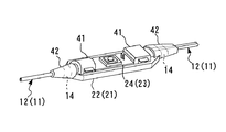
12 マイクコード
13 補強用細線
14 引出し部
21 被接続材
22 本体部
23 ベース部
24 プリント基板
24a 板面
24b 側縁部
25 導入部
26 通孔
27 方形切欠部
28 開口
31 止着材
32 差込み部
33 ストッパー部
34 嵌着材
35 空隙部
41 樹脂成形体
42 ブッシュ部
Claims (3)
- 信号線や電源線として用いられる芯線と、該心線に添設された補強用細線とを少なくとも備えてなるコードと、
該コードの前記芯線が接続される被接続材とで構成され、
該被接続材におけるベース部には、コード側から取り出された前記補強用細線が導入される導入部を設け、
前記コード側から取り出して前記導入部内を挿通させた前記補強用細線の導入部位は、該導入部側に圧接させた止着材を介してベース部側に位置固定させたことを特徴とする被接続材に対するコードの位置固定構造。 - 被接続材の前記ベース部は微小なプリント基板であり、前記コードは細径なマイクコードである請求項1に記載の被接続材に対するコードの位置固定構造。
- 前記被接続材への前記コード側の位置固定部位は、該コードの引出し部を保護するブッシュ部を含めて一体成形された樹脂成形体により一体化した請求項1または請求項2に記載の被接続材に対するコードの位置固定構造。
Priority Applications (2)
| Application Number | Priority Date | Filing Date | Title |
|---|---|---|---|
| JP2004340088A JP4553699B2 (ja) | 2004-11-25 | 2004-11-25 | 被接続材に対するコードの位置固定構造 |
| KR1020050112730A KR20060059189A (ko) | 2004-11-25 | 2005-11-24 | 피접속부재에 대한 전기코드의 고정장치 |
Applications Claiming Priority (1)
| Application Number | Priority Date | Filing Date | Title |
|---|---|---|---|
| JP2004340088A JP4553699B2 (ja) | 2004-11-25 | 2004-11-25 | 被接続材に対するコードの位置固定構造 |
Publications (2)
| Publication Number | Publication Date |
|---|---|
| JP2006157103A true JP2006157103A (ja) | 2006-06-15 |
| JP4553699B2 JP4553699B2 (ja) | 2010-09-29 |
Family
ID=36634910
Family Applications (1)
| Application Number | Title | Priority Date | Filing Date |
|---|---|---|---|
| JP2004340088A Expired - Fee Related JP4553699B2 (ja) | 2004-11-25 | 2004-11-25 | 被接続材に対するコードの位置固定構造 |
Country Status (2)
| Country | Link |
|---|---|
| JP (1) | JP4553699B2 (ja) |
| KR (1) | KR20060059189A (ja) |
Cited By (1)
| Publication number | Priority date | Publication date | Assignee | Title |
|---|---|---|---|---|
| JP2010206662A (ja) * | 2009-03-05 | 2010-09-16 | Audio Technica Corp | コードの端部加工方法およびその端部構造 |
Citations (2)
| Publication number | Priority date | Publication date | Assignee | Title |
|---|---|---|---|---|
| JPS5671688U (ja) * | 1979-11-05 | 1981-06-12 | ||
| JPH09190842A (ja) * | 1996-01-09 | 1997-07-22 | Yazaki Corp | 高圧ケーブル |
-
2004
- 2004-11-25 JP JP2004340088A patent/JP4553699B2/ja not_active Expired - Fee Related
-
2005
- 2005-11-24 KR KR1020050112730A patent/KR20060059189A/ko not_active Withdrawn
Patent Citations (2)
| Publication number | Priority date | Publication date | Assignee | Title |
|---|---|---|---|---|
| JPS5671688U (ja) * | 1979-11-05 | 1981-06-12 | ||
| JPH09190842A (ja) * | 1996-01-09 | 1997-07-22 | Yazaki Corp | 高圧ケーブル |
Cited By (1)
| Publication number | Priority date | Publication date | Assignee | Title |
|---|---|---|---|---|
| JP2010206662A (ja) * | 2009-03-05 | 2010-09-16 | Audio Technica Corp | コードの端部加工方法およびその端部構造 |
Also Published As
| Publication number | Publication date |
|---|---|
| KR20060059189A (ko) | 2006-06-01 |
| JP4553699B2 (ja) | 2010-09-29 |
Similar Documents
| Publication | Publication Date | Title |
|---|---|---|
| TW201205976A (en) | Connector for flat cable | |
| JP2006085989A (ja) | Ffc用挿入ガイド | |
| US6268787B1 (en) | Ferrite-core housing case anti-noise component wire harness and electronic equipment | |
| CN109982531B (zh) | 缆线固定组件 | |
| US20070110385A1 (en) | Cable strain relief design for limited space through-hole applications | |
| JP4553699B2 (ja) | 被接続材に対するコードの位置固定構造 | |
| US6334781B1 (en) | Electrical connector for flexibly attaching circuit board | |
| CN218975906U (zh) | 一种汽车线束接头连接装置 | |
| JP3430816B2 (ja) | バッテリポスト用カバー | |
| CN110611217A (zh) | 芯片封装连接器组件 | |
| CN210806110U (zh) | 插头连接器的壳体构造 | |
| CN209804984U (zh) | 一种数字视频接口连接器 | |
| JP5211023B2 (ja) | イヤホンマイクロホン | |
| JPH0542625Y2 (ja) | ||
| CN218941133U (zh) | 电池盖组件及电子设备 | |
| CN221239848U (zh) | 一种分体式连接器加强壳 | |
| CN213846964U (zh) | 一种耳机线装配结构 | |
| JP3051105B2 (ja) | ケーブル連結器 | |
| KR101106675B1 (ko) | 휴대용 단말기의 이어잭 접속 구조 | |
| CN211062936U (zh) | 一种防止内膜或外膜松脱的usb接口 | |
| JPH09119414A (ja) | プリント基板接続補強用固定具 | |
| JP3706498B2 (ja) | リード線の取り出し構造 | |
| JP2588602Y2 (ja) | 接続プラグ | |
| JP4839985B2 (ja) | プラグコネクタ | |
| JPH11168787A (ja) | イヤホーンジャックの防塵キャップ固定構造 |
Legal Events
| Date | Code | Title | Description |
|---|---|---|---|
| A621 | Written request for application examination |
Free format text: JAPANESE INTERMEDIATE CODE: A621 Effective date: 20071022 |
|
| A977 | Report on retrieval |
Free format text: JAPANESE INTERMEDIATE CODE: A971007 Effective date: 20100225 |
|
| A131 | Notification of reasons for refusal |
Free format text: JAPANESE INTERMEDIATE CODE: A131 Effective date: 20100421 |
|
| A521 | Written amendment |
Free format text: JAPANESE INTERMEDIATE CODE: A523 Effective date: 20100603 |
|
| TRDD | Decision of grant or rejection written | ||
| A01 | Written decision to grant a patent or to grant a registration (utility model) |
Free format text: JAPANESE INTERMEDIATE CODE: A01 Effective date: 20100623 |
|
| A01 | Written decision to grant a patent or to grant a registration (utility model) |
Free format text: JAPANESE INTERMEDIATE CODE: A01 |
|
| A61 | First payment of annual fees (during grant procedure) |
Free format text: JAPANESE INTERMEDIATE CODE: A61 Effective date: 20100713 |
|
| FPAY | Renewal fee payment (event date is renewal date of database) |
Free format text: PAYMENT UNTIL: 20130723 Year of fee payment: 3 |
|
| R150 | Certificate of patent or registration of utility model |
Free format text: JAPANESE INTERMEDIATE CODE: R150 |
|
| LAPS | Cancellation because of no payment of annual fees |