JP2006169089A - Slag processing method, processing apparatus and lance - Google Patents
Slag processing method, processing apparatus and lance Download PDFInfo
- Publication number
- JP2006169089A JP2006169089A JP2005010986A JP2005010986A JP2006169089A JP 2006169089 A JP2006169089 A JP 2006169089A JP 2005010986 A JP2005010986 A JP 2005010986A JP 2005010986 A JP2005010986 A JP 2005010986A JP 2006169089 A JP2006169089 A JP 2006169089A
- Authority
- JP
- Japan
- Prior art keywords
- slag
- lance
- molten slag
- molten
- pan
- Prior art date
- Legal status (The legal status is an assumption and is not a legal conclusion. Google has not performed a legal analysis and makes no representation as to the accuracy of the status listed.)
- Granted
Links
Images



Landscapes
- Refinement Of Pig-Iron, Manufacture Of Cast Iron, And Steel Manufacture Other Than In Revolving Furnaces (AREA)
- Carbon Steel Or Casting Steel Manufacturing (AREA)
- Curing Cements, Concrete, And Artificial Stone (AREA)
Abstract
【課題】
COガスの気泡発生をなるべく抑えながら,溶融スラグ全体を均一に加熱及び改質できる手段を提供する。
【解決手段】
スラグ鍋2に入れられた溶融スラグaを加熱して処理する装置1であって,溶融スラグaを加熱するバーナ3と,溶融スラグa中でガスを噴射するためのランス4を備え,前記ランス4には,溶融スラグa中において水平方向にガスを噴射する噴射口10が複数箇所に設けられ,かつ,各噴射口10は,ランス4を中心にして溶融スラグaに旋回流を与えるように同一の旋回方向に指向している。スラグ鍋2に入れられた溶融スラグaを所定時間静置し,その後,溶融スラグaを加熱する工程と溶融スラグaを攪拌する工程とを交互に一回ずつもしくは複数回ずつ行う。
【選択図】 図4
【Task】
Provided is a means capable of uniformly heating and modifying the entire molten slag while suppressing the generation of CO gas bubbles as much as possible.
[Solution]
An apparatus 1 for heating and processing molten slag a placed in a slag pan 2, comprising a burner 3 for heating the molten slag a and a lance 4 for injecting gas in the molten slag a. 4, the injection ports 10 for injecting gas in the horizontal direction in the molten slag a are provided at a plurality of locations, and each of the injection ports 10 gives a swirl flow to the molten slag a around the lance 4. They are oriented in the same turning direction. The molten slag a placed in the slag pan 2 is allowed to stand for a predetermined time, and then the step of heating the molten slag a and the step of stirring the molten slag a are alternately performed once or a plurality of times.
[Selection] Figure 4
Description
本発明は,製鋼工程などで発生するスラグを溶融状態で改質処理する方法と装置およびランスに関する。 The present invention relates to a method, an apparatus, and a lance for reforming slag generated in a steelmaking process or the like in a molten state.
脱りん,脱硫,脱炭精錬によって生成されるスラグ(製鋼スラグ)は,道路路盤材,コンクリート用骨材等に利用される。だが製鋼スラグに含まれる遊離CaOは,水和反応を起こして膨張するため体積安定性が低く,製鋼スラグは,土木工事用の仮設材,道路の地盤改良材,下層路盤材等の低級用途に専ら利用され,より高級用途である上層路盤材,コンクリート用骨材,石材原料等には用いがたい。 Slag (steel slag) generated by dephosphorization, desulfurization, and decarburization refining is used for road roadbed materials, concrete aggregates, and the like. However, free CaO contained in steelmaking slag is low in volume stability because it expands due to a hydration reaction, and steelmaking slag is used for low-grade applications such as temporary materials for civil engineering, road improvement materials, and lower roadbed materials. It is used exclusively, and it is difficult to use it for higher-grade roadbed materials, concrete aggregates, stone materials, etc.
このため,自然養生や蒸気エージングによってスラグ中の遊離CaOの水和反応を促進させる方法が,一般に採用されている。しかしながら,このように自然養生や蒸気エージングを行うためには,膨張特性が無視できるようになるまで長期間の養生と広い敷地が必要となる。またこの方法では,遊離CaOを効果的に消滅させることができず,依然としてスラグの用途が限られてしまう。 For this reason, a method of promoting the hydration reaction of free CaO in slag by natural curing or steam aging is generally employed. However, in order to perform natural curing and steam aging in this way, long-term curing and a large site are required until the expansion characteristics can be ignored. In this method, free CaO cannot be effectively eliminated, and the use of slag is still limited.
そこで従来,転炉から排出された脱炭スラグを溶融状態のまま改質する方法が開示されている(非特許文献1参照)。これは,溶融スラグ中に酸素と珪石を浸漬ランスを通じて吹き込み,スラグ中のFeOを酸化して昇熱しながら改質材によってスラグの塩基度を低減し,未滓化石灰を体積安定性のある化合物に変化させる方法である。また同様に,溶融スラグ中に改質材と昇温材を浸漬ランスから吹き込み,スラグを昇熱させつつ改質材によってスラグの塩基度を低減する方法も開示されている(特許文献1参照)。また,電気炉に貯えた溶融スラグに成分調整剤を装入し,ガスバブリングする方法も開示されている(特許文献2参照)。そして,ランスの形状としては,ランスを中心にして2孔で水平方向にガスを吹出す構造も開示されている(特許文献3参照)。その他,溶鋼を入れた取鍋の底部からガスをバブリングする方法も開示されている(特許文献4参照)。 Therefore, conventionally, a method for reforming decarburized slag discharged from a converter in a molten state has been disclosed (see Non-Patent Document 1). This is because oxygen and silica are blown into the molten slag through a dipping lance, the FeO in the slag is oxidized and heated to reduce the basicity of the slag by the modifier, and the unstabilized lime is a volume-stable compound. It is a method to change to. Similarly, a method of reducing the basicity of the slag with the modifier while blowing the modifier and the temperature raising material from the immersion lance into the molten slag and heating the slag is also disclosed (see Patent Document 1). . In addition, a method of charging a component adjusting agent into molten slag stored in an electric furnace and gas bubbling is also disclosed (see Patent Document 2). And as a shape of a lance, the structure which blows off gas horizontally with two holes centering on a lance is also disclosed (refer patent document 3). In addition, a method of bubbling gas from the bottom of a ladle containing molten steel is also disclosed (see Patent Document 4).
非特許文献1や特許文献1〜4に記載されたように,従来から,ランスからガスを吹出して溶融スラグを攪拌することにより,スラグ鍋に入れられた溶融スラグ全体を加熱し,均一な改質を行うことができることが知られている。しかし,転炉などから排出されてスラグ鍋に入れられた直後の溶融スラグ中には粒鉄が懸濁しており,この懸濁粒鉄の表面に存在する炭素と溶融スラグ中の酸化鉄が反応することにより,溶融スラグ中においてCOガスの気泡が発生する。
かようなCOガスの発生は,時間経過とともに粒鉄が自重でスラグ鍋の底部に沈降することにより次第に収まっていくが,上述の従来方法のようにランスからガスを吹出して溶融スラグを攪拌した場合,粒鉄の円滑な沈降が妨げられ,COガスの気泡の発生がなかなか収まらなくなってしまう。加えて従来は,スラグ鍋の底部に一旦沈降した粒鉄が,ガスの吹出しによって再び舞い上げられて溶融スラグ中に懸濁した状態となり,COガスの気泡発生が更に長期化するといった懸念もあった。このように,均一な改質という点では,従来方法のようにガスの吹出しによって溶融スラグを攪拌することが好ましいが,そうすると,COガスの気泡発生がなかなか収まらなくなってしまうという問題があった。
As described in Non-Patent Document 1 and Patent Documents 1 to 4, conventionally, the entire molten slag contained in the slag pan is heated by blowing gas from the lance and stirring the molten slag, and uniform modification. It is known that quality can be done. However, the granular iron is suspended in the molten slag immediately after being discharged from the converter and placed in the slag pan, and the carbon present on the surface of the suspended granular iron reacts with the iron oxide in the molten slag. As a result, CO gas bubbles are generated in the molten slag.
The generation of such CO gas gradually subsides as the granular iron settles down to the bottom of the slag pan with its own weight over time, but the molten slag was stirred by blowing gas from the lance as in the conventional method described above. In such a case, the smooth sedimentation of the granular iron is hindered, and the generation of CO gas bubbles is difficult. In addition, conventionally, there is a concern that the granular iron once settled at the bottom of the slag pan is lifted up again by gas blowing and suspended in the molten slag, and the generation of CO gas bubbles is further prolonged. It was. As described above, in terms of uniform reforming, it is preferable to stir the molten slag by blowing out gas as in the conventional method. However, in this case, there is a problem in that the generation of CO gas bubbles does not easily occur.
本発明の目的は,COガスの気泡発生をなるべく抑えながら,溶融スラグ全体を均一に加熱及び改質できる手段を提供することにある。 An object of the present invention is to provide means capable of uniformly heating and modifying the entire molten slag while suppressing the generation of CO gas bubbles as much as possible.
かかる課題を解決するために,本発明によれば,スラグ鍋に入れられた溶融スラグを所定時間静置し,その後,溶融スラグを加熱する工程と溶融スラグを攪拌する工程とを交互に一回ずつもしくは複数回ずつ行うことを特徴とする,スラグの処理方法が提供される。 In order to solve such a problem, according to the present invention, the molten slag placed in the slag pan is allowed to stand for a predetermined time, and then the step of heating the molten slag and the step of stirring the molten slag are alternately performed once. There is provided a method for treating slag, which is characterized in that it is performed one by one or a plurality of times.
前記溶融スラグを加熱する工程において,スラグの塩基度を低下させる改質材を溶融スラグに溶射しても良い。また,前記溶融スラグを攪拌する工程において,スラグ鍋に挿入したランスから噴射したガスによって溶融スラグを旋回した流動状態とさせても良い。 In the step of heating the molten slag, a modifier that lowers the basicity of the slag may be sprayed onto the molten slag. In the step of stirring the molten slag, the molten slag may be swirled by a gas injected from a lance inserted into the slag pan.
また,以上の処理方法で処理した溶融スラグを,複数の羽根が設置された回転しているドラム上に注入し,スラグを飛散させながら散水冷却することによりスラグを粒化させても良い。 Alternatively, the molten slag treated by the above treatment method may be poured onto a rotating drum provided with a plurality of blades, and the slag may be granulated by cooling with sprinkling while scattering the slag.
また本発明によれば,スラグ鍋に入れられた溶融スラグを加熱して処理する装置であって,溶融スラグを加熱するバーナと,溶融スラグ中でガスを噴射するためのランスを備え,前記ランスには,溶融スラグ中において水平方向にガスを噴射する噴射口が複数箇所に設けられ,かつ,各噴射口は,ランスを中心にして溶融スラグに旋回流を与えるように同一の旋回方向に指向していることを特徴とする,スラグの処理装置が提供される。 According to the present invention, there is provided an apparatus for heating and processing molten slag placed in a slag pan, comprising a burner for heating the molten slag, and a lance for injecting gas in the molten slag. Are provided with a plurality of injection ports for injecting gas in the horizontal direction in the molten slag, and each injection port is directed in the same swirling direction so as to give a swirling flow to the molten slag around the lance. An apparatus for treating slag is provided.
前記ランスは円筒形状であり,各噴射口は,ランスの半径に対して同一方向に傾斜していても良い。また,前記各噴射口は,互いに同じ高さに配置されていても良い。更に,前記バーナは,スラグの塩基度を低下させる改質材を溶射できるものであっても良い。 The lance may have a cylindrical shape, and each injection port may be inclined in the same direction with respect to the radius of the lance. In addition, the injection ports may be arranged at the same height. Furthermore, the burner may be capable of spraying a modifier that reduces the basicity of the slag.
また本発明によれば,溶融金属もしくは溶融スラグ中にガスを噴射するためのランスであって,ガスを噴射する噴射口が複数箇所に設けられ,かつ,各噴射口は,ランスを中心にして溶融金属もしくは溶融スラグに旋回流を与えるように同一の旋回方向に指向していることを特徴とする,ランスが提供される。 According to the present invention, there is provided a lance for injecting gas into molten metal or molten slag, and the injection ports for injecting gas are provided at a plurality of locations, and each injection port is centered on the lance. A lance is provided, characterized by being directed in the same swirl direction so as to impart a swirl flow to the molten metal or molten slag.
本発明によれば,粒鉄をスラグ鍋の底部に沈降させた気泡の発生しにくい状態で溶融スラグを加熱することにより,伝熱効率を向上させて溶融スラグを効率良く加熱することができ,溶融スラグ中に含まれる遊離CaOを効果的に低減することが可能となる。また,粒状スラグを製造する際に,併せて粒鉄の分離を図ることも可能となる。溶融スラグを攪拌する場合,ランスを中心にして溶融スラグを旋回させることにより,予めスラグ鍋の底部に沈降させた粒鉄を再び溶融スラグ中に懸濁させずに,スラグ鍋の底部に沈降させた状態を維持させたまま溶融スラグを攪拌できるようになる。このため,COガスの気泡発生が抑制される。また,スラグ中から粒鉄を精度良く分離できるようになり,スラグの改質および品質向上がはかれる。 According to the present invention, the molten slag can be efficiently heated by heating the molten slag in a state where it is difficult for bubbles to be generated by allowing the granular iron to settle to the bottom of the slag pan, and the molten slag can be efficiently heated. It becomes possible to effectively reduce free CaO contained in the slag. In addition, when producing granular slag, it is also possible to separate the granular iron. When stirring the molten slag, the molten iron is swirled around the lance so that the granular iron that has previously settled at the bottom of the slag pan is allowed to settle at the bottom of the slag pan without being suspended again in the molten slag. The molten slag can be agitated while maintaining the maintained state. For this reason, generation | occurrence | production of the bubble of CO gas is suppressed. In addition, granular iron can be separated from slag with high accuracy, and slag can be improved and quality can be improved.
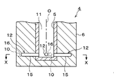
以下,本発明の好ましい実施の形態を図面を参照にして説明する。図1は,本発明の実施の形態にかかる処理装置1の概略的な構成を示す説明図である。図2は,この処理装置1に備えられるランス4の下端部における部分拡大縦断面図(図3におけるY−Y断面図)であり,図3は,ランス4の下端部における拡大横断面図(図2におけるX−X断面図)である。図4は,本発明の実施の形態にかかる溶融スラグaの処理方法の工程説明図である。
Hereinafter, preferred embodiments of the present invention will be described with reference to the drawings. FIG. 1 is an explanatory diagram showing a schematic configuration of a processing apparatus 1 according to an embodiment of the present invention. 2 is a partially enlarged longitudinal sectional view (YY sectional view in FIG. 3) of the lower end portion of the
図1に示すように,スラグ鍋2は,上面が開口し,底面が閉塞された略円筒形状の容器である。後述するように,このスラグ鍋2には,例えば製鋼工程から排出された溶融スラグ(溶銑予備処理スラグ)aが溶融状態のまま入れられる。
As shown in FIG. 1, the
スラグ鍋2の上方には,スラグ鍋2に入れられた溶融スラグaを加熱するためのバーナ3と,溶融スラグaを攪拌するためのランス4が配置される。これらバーナ3とランス4は,それぞれの移動機構(図示せず)によって支持されている。それによって,バーナ3は,スラグ鍋2に入れられた溶融スラグaの液面から所定の高さの位置に移動させられるようになっている。一方,ランス4は,スラグ鍋2に入れられた溶融スラグaの液中にランス4先端の噴射口10を浸漬させた位置に移動可能になっている。
Above the
バーナ3は,例えばLPG,重油,微粉炭,排プラスチックなどを燃料として,スラグ鍋2に入れられた溶融スラグaに向って火炎を照射する。また,バーナ3は,そのように火炎を噴出して溶融スラグaを加熱すると共に,スラグの塩基度を低下させる改質材を,必要に応じて溶融スラグaの液面に向って溶射できるようになっている。
The burner 3 irradiates a flame toward the molten slag a placed in the
図2,3に示すように,ランス4は,底面が閉塞した円筒形状のランス本体5と,このランス本体5の外周面及び下面を被覆した耐火物6とで構成されており,ランス4全体も円筒形状に形成される。ランス本体5は例えば鋼製である。ランス4の下端部には,外周面に開口する噴射口10が複数箇所に設けられている。図示の例では,ランス4の下端部外周面に4つの噴射口10が開口しており,各噴射口10同士は,ランス4の中心軸O(鉛直方向)に対して,中心角が90℃ずつとなる間隔で配置されている。また,これら各噴射口10は,互いに同じ高さに配置されている。
As shown in FIGS. 2 and 3, the
各噴射口10には,ランス4の内部空間(ランス本体5の内部空間)11に連通する連通路12が接続される。各連通路12は,何れも各噴射口10と同じ高さにおいて連通するように設けられている。
Each
連通路12は,ランス4の内部空間11に直接連通する連通路内側部15と噴射口10に直接連通する連通路外側部16からなり,連通路内側部15は,ランス4の中心軸Oから放射状に延びるランス4の半径rに沿う方向に指向している。これに対して,ランス4外周面の噴射口10に直接連通する連通路外側部16は,上から見た状態において,ランス4の半径rに対していずれも時計回転方向に角度αずつ傾斜して設けられている。これにより,後述するようにランス4の内部空間11にガスを圧入すると,噴射口10からランス4の外側に向って水平面内にガスが吹出され,その際,ガスの圧力によって,ランス4の周りにある溶融スラグaに対して,ランス4を中心にして時計回転方向(上から見た状態において)の旋回流を発生させるようになっている。
The
さて,以上のように構成された処理装置1において,例えば転炉から排出された溶融スラグaが溶融状態のままスラグ鍋2に入れられる。なお,このように溶融スラグaをスラグ鍋2に入れる場合は,図示しないそれぞれの移動機構により,バーナ3とランス4を,作業の邪魔とならない位置に退避させておく。
Now, in the processing apparatus 1 configured as described above, for example, the molten slag a discharged from the converter is put into the
図4(a)に示すように,こうしてスラグ鍋2に入れられた直後の溶融スラグa中には粒鉄20がまだ懸濁しており,この懸濁した粒鉄20の表面に付着した炭素と溶融スラグa中に含有される酸化鉄が反応することにより,溶融スラグa中においてCOガスの気泡21が発生する。なお,このようにスラグ鍋2に溶融スラグaを入れた際には,溶融スラグaがスラグ鍋2の内面に接触して部分的に冷却固化されることにより,スラグ鍋2の内面に沿って,スラグの固化層22が形成されることになる。
As shown in FIG. 4 (a), the
そこで先ず,このように転炉などから排出されてスラグ鍋2に入れられた直後から,溶融スラグaを所定時間静置し,溶融スラグa中に懸濁していた粒鉄20を,図4(b)に示すように,スラグ鍋2の底部に充分に沈降させてしまう。この場合,静置する時間は,粒鉄20の沈降速度と溶融プールの深さ(溶融スラグaの深さ)で決る。つまり,静置時間は溶融プール深さを沈降速度で割った値よりも大きくとれば良い。沈降速度は,ストークスの式に支配され,粒鉄20の大きさと溶融スラグaの粘性で決る。例えば粘性1.43Pa・s(気泡を体積割合で67%含有している発泡スラグを想定)で粒径1.0mmの粒鉄20の沈降速度を計算すると2.21mm/secとなり,溶融プール深さ1000mmとすると,452sec(約7.5分)以上静置すれば粒径1mm以上の粒鉄20はすべて沈降することになる。ここで,粒径1.0mm以上の粒鉄20を対象としたのは,粒径1.0mm未満では沈降に時間がかかりすぎ,実際的でないことや,また,沈降させても鉄原料として使用しにくいことが,その理由である。また溶融プール深さ1000mmというのは,実操業面ではほぼ最小の高さであるため,この高さを目安としたことによる。したがって,溶融プール深さが大きな場合,それに応じて静置する時間を長く設定することが重要である。実際は,発泡によるスラグの流動により,上記推定よりは沈降効率が悪い。そこで,上記推定時間の2倍以上の時間を目安に静置することが望ましい。なお,こうして粒鉄20を沈降させている間に,溶融スラグa中に存在していた気泡21は浮上して排出されるので,溶融スラグaの液面高さは徐々に下がっていく。
First, immediately after being discharged from the converter or the like and placed in the
こうして粒鉄20をスラグ鍋2の底部に充分に沈降させた後,溶融スラグaを加熱する工程を行う。即ち,先ず図示しない移動機構によって,バーナ3をスラグ鍋2に入れられた溶融スラグaの液面から所定の高さの位置に移動させる。この場合,バーナ3下端の噴出口から噴出される火炎25の温度の最も高くなる位置が,溶融スラグaの液面付近となるように設定すると良い。次いで,図4(c)に示すように,バーナ3から溶融スラグaの液面に向って下向きに火炎25を噴出し,溶融スラグaを加熱する。これにより,溶融スラグaの液面付近に,溶融スラグaの高温領域a’が徐々に形成される。この場合,前述のように粒鉄20をスラグ鍋2の底部に沈降させる過程で溶融スラグa中に混入していた気泡21を浮上排出させ,粒鉄20を沈降させた気泡の発生しにくい状態で溶融スラグaを加熱しているので,伝熱効率を向上させて溶融スラグaを内部まで効率良く加熱することが可能となる。
After the
また,このように溶融スラグaを加熱する工程において,バーナ3から溶融スラグaに向けて,スラグの塩基度を低下させる改質材を溶射しても良い。改質材としては,溶融スラグaよりも塩基度(CaO/SiO2(質量比))が低いものであれば特に限定されないが,例えばSiO2を含有する物質を溶射しても良い。SiO2を含有する物質としては,フライアッシュ,珪砂等が例示できる。また,改質材の溶射量は,溶融スラグaの成分や温度,目標とする改質スラグの成分等から,適宜設定すれば良い。 Further, in the step of heating the molten slag a in this way, a modifier that lowers the basicity of the slag may be sprayed from the burner 3 toward the molten slag a. The modifying material is not particularly limited as long as the basicity (CaO / SiO 2 (mass ratio)) is lower than that of the molten slag a, but for example, a material containing SiO 2 may be sprayed. Examples of the substance containing SiO 2 include fly ash and silica sand. The amount of spraying of the reforming material may be appropriately set based on the component and temperature of the molten slag a, the target component of the reforming slag, and the like.
こうして溶融スラグaの液面付近に高温領域a’を形成させた後,バーナ3を退避させる。次いで図示しない移動機構によってランス4を移動させて,図4(d)に示すようにスラグ鍋2のほぼ中央にランス4を挿入し,噴射口10をスラグ鍋2に入れられた溶融スラグaの液中に浸漬させた状態にする。そして,ランス4の内部空間11に例えば空気,酸素,窒素等のガスを圧入して,ランス4の下端部外周面に開口している噴射口10から溶融スラグa中にガス26を噴射する。
Thus, after the high temperature region a 'is formed near the liquid surface of the molten slag a, the burner 3 is retracted. Next, the
こうして溶融スラグa中において複数の噴射口10からランス4の外側に向ってガス26を噴射すると,先に図2,3において説明したように,溶融スラグaに対して,ランス4を中心にした時計回転方向の旋回流が与えられる。こうして,スラグ鍋2内の溶融スラグaはランス4を中心にして時計回転方向に旋回しながら,全体的に攪拌されていく。
Thus, when the
このようにスラグ鍋2内の溶融スラグaを攪拌することにより,溶融スラグaの温度を均一化して流動性を向上させ,溶融スラグa中からの気泡の浮上排出を促進させることができる。また同時に,溶融スラグa中に存在する遊離CaOを溶融スラグa中や溶射した改質材に含まれるSiO2などと反応させて,体積安定性のある化合物(2CaO・SiO2等)に変化させることができ,溶融スラグa全体について均一な改質を施すことがで
きる。なお,ランス4の噴射口10から溶融スラグa中に酸素を吹込んだ場合は,溶融スラグa中のFeOを酸化させ,その際に発生する酸化熱によって溶融スラグaの流動性を向上させ,その結果,溶融改質を更に促進させることができるようになる。
By stirring the molten slag a in the
こうしてバーナ3による加熱操作とランス4による攪拌操作を,もしくは,バーナ3による加熱操作および改質材の溶射操作とランス4による攪拌操作を,1回ずつもしくは複数回ずつ適宜交互に行うことにより,気泡の除去と溶融スラグaの改質を行った後,図4(e)に示すように,スラグ鍋2を傾け,改質された溶融スラグaを取鍋30に排出する。この場合,スラグ鍋2の傾け角度や傾ける際の速度を適宜調節することにより,スラグ鍋2の底部に沈降させた粒鉄20を取鍋30に流し出さないように注意すると良い。なお,前述のようにスラグ鍋2の内面に沿ってスラグの固化層22が形成されるが,スラグ鍋2の底部に沈降した粒鉄20がこの固化層22内に固定されている場合は,スラグ鍋2を傾け角度を多少大きくしても,粒鉄20が取鍋30に流れ出る心配がない。
Thus, the heating operation by the burner 3 and the stirring operation by the
なお図4(e)では,溶融改質処理によって得られた溶融スラグを取鍋30に排滓し,スラグ塊を製作する場合を説明したが,スラグから砂や細骨材を直接製造する場合には,図4の(c)や(d)で説明した工程を行った後に,図5に示す様に,スラグ鍋2を傾けてスラグ鍋2中の溶融スラグaを複数の羽根が設置された高速回転(通常はドラム周速;1〜30m/秒程度)している回転ドラム40上に注入して,スラグを粒状に飛散させると良い。そして,散水ノズル41から散水した冷却水を飛散させたスラグに接触させて冷却固化(通常は,冷却水量/スラグ質量;0.2〜3.0m3/ton・スラグ程度である)させることにより,粒化させたスラグを得ることができる。こうして得られた粒状のスラグは,道路路盤材,コンクリート用骨材等の砂や細骨材として利用することができる。
In addition, in FIG.4 (e), although the case where the molten slag obtained by the melt-modification process was discharged to the
この場合,図5に示すように,回転ドラム40からの距離に応じて複数のバケット42を並べて配置し,回転ドラム40の回転によって飛散させた粒状のスラグを,飛散位置(飛散距離)毎に分けて各バケット42内に回収しても良い。図4の(c)や(d)で説明した工程を行った後の状態では,溶融スラグa中に粒鉄がまだある程度含有されているが,このように回転ドラム40の回転によってスラグを粒状に飛散させ,その飛散位置毎に分級して粒状のスラグを回収することにより,粒状のスラグと粒鉄との分離を容易にすることが可能となる。
In this case, as shown in FIG. 5, a plurality of
即ち本発明者らの知見によれば,このように回転ドラム40の回転で粒状に飛散させたスラグを飛散位置毎に分級して回収すると,図6に示すように,飛散距離(スラグ回収位置(L))が大きいものほど粒鉄含有量が少なく,飛散距離が小さいものほど粒鉄含有量が多い,ということが判明した。なお,図6において横軸のスラグ回収位置(L)は,粒子状スラグの回転ドラムからの飛散限界距離をL=1とし,粒子状スラグの飛散距離を相対値で示している。また,縦軸の粒鉄割合は,それぞれの飛散距離に応じて各バケット内42に回収された粒子状スラグの粒鉄の質量割合(%)を示している。この図6から,回収位置を選択することにより,磁選を実施しなくとも,粒鉄を含有しない粒子状スラグを得ることができ,また,粒鉄を多く含む粒子状スラグにおいては,その後の磁選による粒鉄の分離回収を効率良くできることが理解される。
That is, according to the knowledge of the present inventors, when the slag dispersed in a granular form by the rotation of the
以上に説明した本発明の実施の形態によれば,溶融スラグaを攪拌する工程において,スラグ鍋2のほぼ中央に挿入したランス4を中心にして溶融スラグaを旋回させることにより,スラグ鍋2の底部に沈降させた粒鉄20を舞い上げずに,スラグ鍋2の底部に沈降させた状態を維持させたまま溶融スラグaを攪拌できる。このため,COガスの気泡発生を抑制しながら,気泡の除去と溶融スラグaの改質を行うことができる。また,スラグ中から粒鉄を精度良く分離できるので,スラグの品質向上がはかれる。こうして改質処理されたスラグは,水浸膨張比が低減され,強度が向上したものとなる。このため,処理されたスラグは,上層路盤材,アスファルト混合道路用材,アスファルト舗装用骨材,コンクリート用骨材,コンクリート二次製品用原料,窯業・タイル用原料,人工石材原料等の各種有用な原料に適用することができ,再生資源として有効利用できるようになる。また,スラグと分離した粒鉄20は,鉄原料として利用できる。
According to the embodiment of the present invention described above, in the step of stirring the molten slag a, the molten slag a is swiveled around the
以上,本発明の好ましい実施の形態を例示したが,本発明はここで説明した形態に限定されない。例えば,上から見た状態においてスラグ鍋2に入れられた溶融スラグaに反時計回転方向の旋回流を発生させて攪拌しても良いことはもちろんである。また,バーナ3による加熱操作とランス4による攪拌操作は,もしくは,バーナ3による加熱操作および改質材の溶射操作とランス4による攪拌操作は,1回ずつ交互に行っても良いし,複数回ずつ交互に繰り返して行っても良い。
As mentioned above, although preferred embodiment of this invention was illustrated, this invention is not limited to the form demonstrated here. For example, of course, a swirl flow in the counterclockwise direction may be generated and stirred in the molten slag a placed in the
ランス4に設けられる噴射口10は複数箇所にあれば良く,必ずしも4箇所でなくても良い。ランス4を中心にして溶融スラグaに旋回流を生じさせるように,同一の旋回方向に指向しているガスを複数箇所に設けられた噴射口10からそれぞれ噴出させれば良い。また,各噴射口10の高さは必ずしも同じでなくても良く,異なる高さにある複数の噴射口10からそれぞれガスを噴出して,溶融スラグaをランス4を中心に旋回させるようにしても良い。更に,攪拌中,ランス4を上下動させても良い。また,ランス4から溶融スラグa中に吹き込むガスは常温でも良いが,高温ガスを用いれば,溶融スラグaが冷却されるのを回避できる。また,ランス4の代りに,例えば攪拌羽根を用いて,溶融スラグaを機械的に攪拌しても良い。なお,以上に説明したランス4は,水平方向の旋回流を必要とする他の流体(スラグ以外の流体)についても適用可能である。
The
(実施例1)
図1〜3で説明した処理装置において,製鋼工程からの溶銑予備処理スラグ20ton(改質処理前の直径1mm以上の粒鉄量は23質量%)をスラグ鍋に排滓し,15分間静置した。その後,バーナによって溶融スラグ(溶銑予備処理スラグ)を加熱しながら,改質材としてフライアッシュを6400kg/hの速度で5分間溶射した後,直ちにランスを溶融スラグに浸漬させて水平向きにガス(空気)を600Nm3/hで吹き込み,ランスを中心に溶融スラグを回転させて攪拌した。バブリング時間(攪拌時間)は1分間である。こうして,5分のバーナによる加熱とフライアッシュの溶射,1分のランスによるガス攪拌を交互に3回繰り返した。その後,スラグ鍋を傾けて,改質された溶融スラグを排出した。排出されたスラグを粉砕した後に磁選を行った結果,直径1mm以上の粒鉄量は1質量%未満で,改質処理により粒鉄の分離が良好であったことが分かった。加熱および溶射をする工程と,攪拌する工程の何れにおいても発泡現象は起こらず,得られたスラグは吸水率1.0質量%であり,骨材として十分使用可能であった。
Example 1
1-3, the hot
(実施例2)
図1〜3で説明した処理装置において,製鋼工程からの溶銑予備処理スラグ20ton(改質処理前の直径1mm以上の粒鉄量は24質量%)をスラグ鍋に排滓し,静置時間を短くしてスラグ中に粒鉄が懸濁した状態での評価を試みた。前記スラグを5分間静置した後,(直径1mm以上の粒鉄量は20質量%)バーナによって溶融スラグ(溶銑予備処理スラグ)を加熱しながら,改質材としてフライアッシュを6400kg/hの速度で5分間溶射した後,直ちにランスを溶融スラグに浸漬させて水平向きにガス(空気)を600Nm3/hで吹き込み,ランスを中心に溶融スラグを回転させて攪拌した。バブリング時間(攪拌時間)は1分間である。こうして,5分のバーナによる加熱とフライアッシュの溶射,1分のランスによるガス攪拌を交互に5回繰り返した。細骨材を生産するために,スラグ鍋を傾けて,粒鉄が懸濁した改質された溶融スラグを複数の羽根を設置し高速回転(ドラム周速;1〜15m/秒)する回転ドラム上に注入し,スラグを飛散させながら散水冷却(冷却水量/スラグ質量;2.0m3/ton・スラグ)し粒状スラグを製造した。なお,加熱および溶射をする工程と,攪拌する工程の何れにおいて,やや発泡現象が発生する場合があった。
粒状化処理を実施したスラグは,採取位置が回転ドラムに近いL=0〜0.6未満で採取したスラグは,磁選によって容易に粒鉄を取り除くことが可能であり,得られた粒子状スラグは吸水率0.90質量%であった。一方,回転ドラムから遠いL=0.6〜1.0の位置で採取した粒鉄含有量は1質量%未満で問題の無い水準であり(L=0.8〜1.0では僅少),粒子状スラグの吸水率は0.85質量%であった。従って,いずれも砂,細骨材として十分使用可能であり,鎮静時間が短く粒鉄の懸濁量が比較的大きい条件であっても,スラグを粒状化処理することで容易に粒鉄との分離が可能であった。
(Example 2)
1-3, the hot
The slag that has been granulated can be easily removed by magnetic separation from the slag collected at L = 0 to less than 0.6, which is close to the rotating drum, and the obtained particulate slag The water absorption was 0.90% by mass. On the other hand, the content of granular iron collected at a position of L = 0.6 to 1.0 far from the rotating drum is less than 1% by mass, which is a problem-free level (L = 0.8 to 1.0 is very small). The water absorption of the particulate slag was 0.85% by mass. Therefore, both can be used satisfactorily as sand and fine aggregates. Even under conditions where the sedation time is short and the amount of suspended iron is relatively large, the slag can be easily treated with granular iron. Separation was possible.
(実施例3)
図1〜3で説明した処理装置において,製鋼工程からの溶銑予備処理スラグ20ton(改質処理前の直径1mm以上の粒鉄量は25質量%)をスラグ鍋に排滓し,15分間静置した。その後,バーナによって溶融スラグ(溶銑予備処理スラグ)を加熱しながら,改質材としてフライアッシュを6400kg/hの速度で5分間溶射した後,直ちにランスを溶融スラグに浸漬させて水平向きにガス(空気)を600Nm3/hで吹き込み,ランスを中心に溶融スラグを回転させて攪拌した。バブリング時間(攪拌時間)は1分間である。こうして,5分のバーナによる加熱とフライアッシュの溶射,1分のランスによるガス攪拌を交互に5回繰り返した。
ここで,操業中に粒鉄を再度巻き上げた場合の影響を評価する目的で,最後のガス攪拌でランスの浸漬深さを深くして,スラグ鍋の底に沈降した粒鉄を再度巻き上げ,再び粒鉄を沈降させることなく,スラグ鍋を傾けて,粒鉄が懸濁した改質された溶融スラグを,複数の羽根を設置し高速回転(ドラム周速;1〜15m/秒)する回転ドラム上に注入し,スラグを飛散させながら散水冷却(冷却水量/スラグ質量;2.0m3/ton・スラグ)し粒状スラグを製造した。加熱および溶射をする工程と,攪拌する工程の何れにおいても発泡現象は起こらなかったが,再度粒鉄を懸濁させた後にスラグの発泡現象が若干見られた。
粒状スラグの採取位置が回転ドラムに近いL=0〜0.6未満で採取したスラグは,磁選によって容易に粒鉄を取り除くことが可能であり,得られた粒子状スラグは吸水率1.0質量%であった。一方,回転ドラムから遠いL=0.6〜1.0の位置で採取した直径1mm以上の粒鉄含有量は1%未満で問題の無い水準であり(L=0.8〜1.0では僅少),粒子状スラグの吸水率は0.95質量%あった。従って,いずれも砂,細骨材として十分使用可能であった。
(Example 3)
1-3, the hot
Here, for the purpose of evaluating the effect of rewinding the granular iron during operation, the lance immersion depth was increased by the last gas agitation, and the granular iron settled on the bottom of the slag pan was rewinded and again Rotating drum that rotates the slag pan, which has been suspended, and rotates at a high speed (drum peripheral speed: 1 to 15 m / sec) by tilting the slag pan and setting the plurality of blades without causing the granular iron to settle Sprinkling cooling (cooling water amount / slag mass; 2.0 m 3 / ton · slag) was performed while sprinkling slag to produce granular slag. No foaming phenomenon occurred in either the heating and thermal spraying steps or the stirring step, but a slight slag foaming phenomenon was observed after resuspending the granular iron.
Granular iron can be easily removed by magnetic separation from the slag collected at L = 0 to less than 0.6, which is close to the rotating drum, where the granular slag is collected, and the obtained granular slag has a water absorption rate of 1.0. It was mass%. On the other hand, the content of granular iron having a diameter of 1 mm or more collected at a position of L = 0.6 to 1.0 far from the rotating drum is less than 1% and is a level without any problem (at L = 0.8 to 1.0). Slightly), the water absorption of the particulate slag was 0.95% by mass. Therefore, both could be used as sand and fine aggregate.
(比較例)
上記実施例と同様の装置を用いて製鋼工程からの溶銑予備処理スラグ20ton改質処理前の直径1mm以上の粒鉄量は20質量%)をスラグ鍋に排滓し,直ちにバーナで溶融スラグを加熱しながら,改質材としてフライアッシュを6400kg/hの速度で5分間溶射し,更に,溶融スラグに浸漬させた単管ランスから下向きに空気を600Nm3/hで1分間バブリングして溶融スラグを攪拌した。こうして,5分のバーナによる加熱とフライアッシュの溶射,1分の単管ランスによる攪拌を交互に3回繰り返した。その後,スラグ鍋を傾けて,改質された溶融スラグを排出した。
加熱および溶射をする工程と,攪拌する工程の何れにおいても激しい発泡現象が継続して発生し,発泡現象が収まるまで一旦処理を中断した。排出されたスラグには多数の気泡,粒鉄が目視でも確認でき,崩壊しやすいスラグであった。また,スラグの吸水率は7.3質量%であった。
改質スラグを冷却した後にスラグを粉砕し,その後で,磁選を実施することにより粒鉄を回収したところ,直径1mm超の粒鉄は3400kgであり,処理前に存在した粒鉄4000kgの約85%が改質スラグ中に残存していた。従って,改質処理中での粒鉄の分離が十分できていないことがわかった。
(Comparative example)
Using the same equipment as in the above example, the molten iron pretreatment slag 20ton from the steelmaking process was discharged into the slag pan, and the molten slag was immediately removed with a burner. While heating, fly ash was sprayed as a modifier at a rate of 6400 kg / h for 5 minutes, and then air was bubbled downward from a single tube lance immersed in the molten slag for 1 minute at 600 Nm 3 / h for molten slag. Was stirred. Thus, heating with a burner for 5 minutes, spraying of fly ash, and stirring with a single pipe lance were repeated three times alternately. After that, the slag pan was tilted and the modified molten slag was discharged.
In both the heating and thermal spraying steps and the stirring step, a severe foaming phenomenon occurred continuously, and the treatment was suspended until the foaming phenomenon subsided. The discharged slag was a slag that was easy to collapse, as many bubbles and granular iron could be visually confirmed. Moreover, the water absorption rate of the slag was 7.3% by mass.
After the modified slag was cooled, the slag was pulverized, and then the magnetic iron was collected to collect the granular iron. As a result, 3400 kg of granular iron with a diameter of more than 1 mm was obtained, and about 85 of the 4000 kg of granular iron that existed before the treatment. % Remained in the modified slag. Therefore, it was found that the granular iron was not sufficiently separated during the reforming process.
本発明は,製鋼工程等で発生するスラグの処理などに利用される。 The present invention is used for the treatment of slag generated in a steel making process or the like.
1 処理装置
2 スラグ鍋
3 バーナ
4 ランス
5 ランス本体
6 耐火物
10 噴射口
11 内部空間
12 連通路
15 連通路内側部
16 連通路外側部
20 粒鉄
21 気泡
22 スラグの固化層
25 火炎
26 ガス
30 取鍋
40 回転ドラム
41 散水ノズル
42 バケット
a 溶融スラグ
a’ 高温領域
r ランスの半径
DESCRIPTION OF SYMBOLS 1
Claims (9)
溶融スラグを加熱するバーナと,
溶融スラグ中でガスを噴射するためのランスを備え,
前記ランスには,溶融スラグ中において水平方向にガスを噴射する噴射口が複数箇所に設けられ,かつ,各噴射口は,ランスを中心にして溶融スラグに旋回流を与えるように同一の旋回方向に指向していることを特徴とする,スラグの処理装置。 A device that heats and processes molten slag in a slag pan,
A burner for heating the molten slag;
A lance for injecting gas in the molten slag,
The lance is provided with a plurality of injection ports for injecting gas in the horizontal direction in the molten slag, and each injection port has the same swirl direction so as to give a swirl flow to the molten slag around the lance. Slag processing equipment, characterized by
Priority Applications (1)
| Application Number | Priority Date | Filing Date | Title |
|---|---|---|---|
| JP2005010986A JP4593294B2 (en) | 2004-11-19 | 2005-01-18 | Slag processing method and processing apparatus |
Applications Claiming Priority (2)
| Application Number | Priority Date | Filing Date | Title |
|---|---|---|---|
| JP2004336039 | 2004-11-19 | ||
| JP2005010986A JP4593294B2 (en) | 2004-11-19 | 2005-01-18 | Slag processing method and processing apparatus |
Publications (2)
| Publication Number | Publication Date |
|---|---|
| JP2006169089A true JP2006169089A (en) | 2006-06-29 |
| JP4593294B2 JP4593294B2 (en) | 2010-12-08 |
Family
ID=36670230
Family Applications (1)
| Application Number | Title | Priority Date | Filing Date |
|---|---|---|---|
| JP2005010986A Expired - Fee Related JP4593294B2 (en) | 2004-11-19 | 2005-01-18 | Slag processing method and processing apparatus |
Country Status (1)
| Country | Link |
|---|---|
| JP (1) | JP4593294B2 (en) |
Cited By (7)
| Publication number | Priority date | Publication date | Assignee | Title |
|---|---|---|---|---|
| JP2013130314A (en) * | 2011-12-20 | 2013-07-04 | Kawasaki Heavy Ind Ltd | Slag melting device and gasification melting device including the same |
| KR101482510B1 (en) * | 2013-08-07 | 2015-01-19 | 주식회사 우진 | slag out-flow prevention apparatus and high prssure gas shooting lamce therein |
| US10174389B2 (en) * | 2013-11-28 | 2019-01-08 | Voestalpine Stahl Gmbh | Method for treating desulfurization slag |
| WO2019161638A1 (en) * | 2018-02-26 | 2019-08-29 | 西安交通大学 | Liquid slag dry centrifugal granulation and waste heat recovery system having slag buffer and flow control function |
| CN111074022A (en) * | 2019-12-04 | 2020-04-28 | 西安交通大学 | Operation method of liquid slag caching and flow control device |
| JP2021147671A (en) * | 2020-03-19 | 2021-09-27 | 日本製鉄株式会社 | Method for cooling molten iron pre-treatment slag |
| CN114105656A (en) * | 2021-11-25 | 2022-03-01 | 吴丽贤 | Production method of novel roasting-sintering desulfurization gun with high-temperature adhesive |
Citations (8)
| Publication number | Priority date | Publication date | Assignee | Title |
|---|---|---|---|---|
| JPS5323325A (en) * | 1976-08-16 | 1978-03-03 | Nippon Steel Corp | Modification treatment process for converter slag |
| JPS5765952U (en) * | 1980-10-07 | 1982-04-20 | ||
| JPS6287443A (en) * | 1985-10-09 | 1987-04-21 | 日本磁力選鉱株式会社 | Treatment of steel slag |
| JPH0519341U (en) * | 1991-08-19 | 1993-03-09 | 住友金属工業株式会社 | Lance for powder injection into molten metal |
| JP2000202401A (en) * | 1999-01-19 | 2000-07-25 | Nkk Corp | Method for producing slag for rock wool and method for producing rock wool |
| JP2003146712A (en) * | 2001-11-08 | 2003-05-21 | Nippon Steel Corp | Cooling method of granulation equipment for molten slag |
| JP2004331449A (en) * | 2003-05-07 | 2004-11-25 | Nippon Steel Corp | Melt reforming method for steelmaking slag |
| JP2006199984A (en) * | 2005-01-18 | 2006-08-03 | Nippon Steel Corp | Slag processing method |
-
2005
- 2005-01-18 JP JP2005010986A patent/JP4593294B2/en not_active Expired - Fee Related
Patent Citations (8)
| Publication number | Priority date | Publication date | Assignee | Title |
|---|---|---|---|---|
| JPS5323325A (en) * | 1976-08-16 | 1978-03-03 | Nippon Steel Corp | Modification treatment process for converter slag |
| JPS5765952U (en) * | 1980-10-07 | 1982-04-20 | ||
| JPS6287443A (en) * | 1985-10-09 | 1987-04-21 | 日本磁力選鉱株式会社 | Treatment of steel slag |
| JPH0519341U (en) * | 1991-08-19 | 1993-03-09 | 住友金属工業株式会社 | Lance for powder injection into molten metal |
| JP2000202401A (en) * | 1999-01-19 | 2000-07-25 | Nkk Corp | Method for producing slag for rock wool and method for producing rock wool |
| JP2003146712A (en) * | 2001-11-08 | 2003-05-21 | Nippon Steel Corp | Cooling method of granulation equipment for molten slag |
| JP2004331449A (en) * | 2003-05-07 | 2004-11-25 | Nippon Steel Corp | Melt reforming method for steelmaking slag |
| JP2006199984A (en) * | 2005-01-18 | 2006-08-03 | Nippon Steel Corp | Slag processing method |
Cited By (8)
| Publication number | Priority date | Publication date | Assignee | Title |
|---|---|---|---|---|
| JP2013130314A (en) * | 2011-12-20 | 2013-07-04 | Kawasaki Heavy Ind Ltd | Slag melting device and gasification melting device including the same |
| KR101482510B1 (en) * | 2013-08-07 | 2015-01-19 | 주식회사 우진 | slag out-flow prevention apparatus and high prssure gas shooting lamce therein |
| WO2015020261A1 (en) * | 2013-08-07 | 2015-02-12 | (주)우진 | Device for preventing slag outflow and high pressure gas injection lance used therein |
| US10174389B2 (en) * | 2013-11-28 | 2019-01-08 | Voestalpine Stahl Gmbh | Method for treating desulfurization slag |
| WO2019161638A1 (en) * | 2018-02-26 | 2019-08-29 | 西安交通大学 | Liquid slag dry centrifugal granulation and waste heat recovery system having slag buffer and flow control function |
| CN111074022A (en) * | 2019-12-04 | 2020-04-28 | 西安交通大学 | Operation method of liquid slag caching and flow control device |
| JP2021147671A (en) * | 2020-03-19 | 2021-09-27 | 日本製鉄株式会社 | Method for cooling molten iron pre-treatment slag |
| CN114105656A (en) * | 2021-11-25 | 2022-03-01 | 吴丽贤 | Production method of novel roasting-sintering desulfurization gun with high-temperature adhesive |
Also Published As
| Publication number | Publication date |
|---|---|
| JP4593294B2 (en) | 2010-12-08 |
Similar Documents
| Publication | Publication Date | Title |
|---|---|---|
| JP2006528732A (en) | Slag utilization process | |
| JP4593294B2 (en) | Slag processing method and processing apparatus | |
| BR112019010696B1 (en) | ELECTRIC OVEN | |
| JP2019119906A (en) | Converter refining method | |
| JP2018024898A (en) | Dephosphorization method of molten pig iron excellent in dephosphorization efficiency and iron content yield | |
| JP4388482B2 (en) | Slag processing method | |
| TWI844330B (en) | Direct-reduction iron melting method, solid iron and method for producing solid iron, civil engineering and construction material and method for producing civil engineering and construction material | |
| JP7158570B2 (en) | Method for refining molten iron alloys with high efficiency | |
| US2950186A (en) | Method for top blowing pulverulent burnt lime and oxygen into cast iron for refining same | |
| JP4937818B2 (en) | Method of melt reforming steelmaking slag | |
| TWI843517B (en) | Direct-reduction iron melting method, solid iron and method for producing solid iron, civil engineering and construction material and method for producing civil engineering and construction material, and direct-reduction iron melting system | |
| JP2006144078A (en) | Slag processing method, processing apparatus and lance | |
| TWI703219B (en) | Dephosphorization method of hot metal | |
| JP3905879B2 (en) | Method for melt reforming steelmaking slag | |
| JP4288101B2 (en) | Method for melt reforming steelmaking slag | |
| JP2014521837A (en) | Method and apparatus for dephosphorizing liquid hot metal such as liquid blast furnace | |
| JP5309740B2 (en) | A container for melt reforming of steelmaking slag | |
| JP4191867B2 (en) | Manufacturing method of hard artificial aggregate | |
| JP4511909B2 (en) | Steelmaking slag treatment method | |
| JP6289204B2 (en) | Desiliconization and desulfurization methods in hot metal ladle | |
| JP4191866B2 (en) | Manufacturing method of light artificial aggregate made from blast furnace slag and coal ash | |
| EP4150128B1 (en) | Stirring method of liquid metal and associated device | |
| JP3774913B2 (en) | Hot silicon pre-desiliconization method | |
| JP3668172B2 (en) | Hot metal refining method | |
| JP2005195224A (en) | Steelmaking slag melt reforming furnace and melt reforming method |
Legal Events
| Date | Code | Title | Description |
|---|---|---|---|
| A621 | Written request for application examination |
Free format text: JAPANESE INTERMEDIATE CODE: A621 Effective date: 20070904 |
|
| A977 | Report on retrieval |
Free format text: JAPANESE INTERMEDIATE CODE: A971007 Effective date: 20100215 |
|
| A131 | Notification of reasons for refusal |
Free format text: JAPANESE INTERMEDIATE CODE: A131 Effective date: 20100629 |
|
| A521 | Written amendment |
Free format text: JAPANESE INTERMEDIATE CODE: A523 Effective date: 20100816 |
|
| TRDD | Decision of grant or rejection written | ||
| A01 | Written decision to grant a patent or to grant a registration (utility model) |
Free format text: JAPANESE INTERMEDIATE CODE: A01 Effective date: 20100907 |
|
| A01 | Written decision to grant a patent or to grant a registration (utility model) |
Free format text: JAPANESE INTERMEDIATE CODE: A01 |
|
| A61 | First payment of annual fees (during grant procedure) |
Free format text: JAPANESE INTERMEDIATE CODE: A61 Effective date: 20100915 |
|
| FPAY | Renewal fee payment (event date is renewal date of database) |
Free format text: PAYMENT UNTIL: 20130924 Year of fee payment: 3 |
|
| R151 | Written notification of patent or utility model registration |
Ref document number: 4593294 Country of ref document: JP Free format text: JAPANESE INTERMEDIATE CODE: R151 |
|
| FPAY | Renewal fee payment (event date is renewal date of database) |
Free format text: PAYMENT UNTIL: 20130924 Year of fee payment: 3 |
|
| S533 | Written request for registration of change of name |
Free format text: JAPANESE INTERMEDIATE CODE: R313533 |
|
| FPAY | Renewal fee payment (event date is renewal date of database) |
Free format text: PAYMENT UNTIL: 20130924 Year of fee payment: 3 |
|
| R350 | Written notification of registration of transfer |
Free format text: JAPANESE INTERMEDIATE CODE: R350 |
|
| LAPS | Cancellation because of no payment of annual fees |