JP2006185444A - Evolutionary optimization method and free form deformation method - Google Patents
Evolutionary optimization method and free form deformation method Download PDFInfo
- Publication number
- JP2006185444A JP2006185444A JP2005369232A JP2005369232A JP2006185444A JP 2006185444 A JP2006185444 A JP 2006185444A JP 2005369232 A JP2005369232 A JP 2005369232A JP 2005369232 A JP2005369232 A JP 2005369232A JP 2006185444 A JP2006185444 A JP 2006185444A
- Authority
- JP
- Japan
- Prior art keywords
- deformation
- evolutionary
- spline
- design
- evolutionary computation
- Prior art date
- Legal status (The legal status is an assumption and is not a legal conclusion. Google has not performed a legal analysis and makes no representation as to the accuracy of the status listed.)
- Pending
Links
Images



Classifications
-
- G—PHYSICS
- G06—COMPUTING OR CALCULATING; COUNTING
- G06T—IMAGE DATA PROCESSING OR GENERATION, IN GENERAL
- G06T17/00—Three-dimensional [3D] modelling for computer graphics
- G06T17/30—Polynomial surface description
Landscapes
- Physics & Mathematics (AREA)
- Engineering & Computer Science (AREA)
- General Physics & Mathematics (AREA)
- Pure & Applied Mathematics (AREA)
- Mathematical Optimization (AREA)
- Mathematical Physics (AREA)
- Mathematical Analysis (AREA)
- Algebra (AREA)
- Computer Graphics (AREA)
- Geometry (AREA)
- Software Systems (AREA)
- Theoretical Computer Science (AREA)
- Image Generation (AREA)
- Processing Or Creating Images (AREA)
Abstract
Description
本発明は、設計最適化および進化的計算を用いた自由形状変形に関する。 The present invention relates to freeform deformation using design optimization and evolutionary computation.
設計最適化問題に最適化アルゴリズムを適用するためには、最適化アルゴリズムによって変更できるパラメータの組によって設計の形態を記述する形を見つけることが必須である。周知の方法は、たとえば、最適化される物体の表面を記述する、2次元表面の場合にスプライン曲線、3次元設計の場合にスプライン曲面を定義することである。この場合に、最適化アルゴリズムによって変更されるパラメータは、制御点およびノット点(knot point)であり、さらに、NURBS(non-uniform rational B-spline、非一様有理式Bスプライン)の場合に、制御点の重みがある。所与の設計を表すもう1つの形が、基礎設計が与えられる空間を変換する変換関数を定義することである。この場合に、形態の変形は、変換関数のパラメータを変更することによって実現することができる。この方法を、自由形状変形(free form deformation:FFD)という用語の下で要約することができる。 In order to apply an optimization algorithm to a design optimization problem, it is essential to find a form that describes the design form by a set of parameters that can be changed by the optimization algorithm. A well-known method is to define, for example, a spline curve in the case of a two-dimensional surface, a spline surface in the case of a three-dimensional design, which describes the surface of the object to be optimized. In this case, the parameters changed by the optimization algorithm are control points and knot points, and in the case of NURBS (non-uniform rational B-spline), There are control point weights. Another way to represent a given design is to define a transformation function that transforms the space in which the base design is given. In this case, deformation of the form can be realized by changing parameters of the conversion function. This method can be summarized under the term free form deformation (FFD).
従来技術:自由形状変形
したがって、自由形状変形は、従来技術で既知であり、次で短く説明する。
Prior art: Free form deformation Thus, free form deformation is known in the prior art and will be briefly described below.
拘束付き変形
この原理は、BorrelおよびBechman(非特許文献2)によって定式化された。彼らは、任意の個数のユーザ指定の点の変位拘束(displacement constraint)によって定義される一般変形方式を開発した。BorrelおよびBechmannの変形方法を、図1に示すが、この方法は、次の原理に基づく:原空間および変形された空間Rnは、より高次元の空間Rmの2つの射影である。したがって、変形は、オリジナル空間Rnの点をRmの点に変換する関数f:Rn→Rmと、RmからRnへの射影Tの合成によって定義される。射影行列は、原空間の所与の点(拘束点(constraints points)と呼ぶ)の所与の変位(拘束(constraints)と呼ぶ)を達成するように計算される。
Constrained deformation This principle was formulated by Borrel and Bechman (2). They have developed a general deformation scheme defined by displacement constraints for any number of user-specified points. The Borrel and Bechmann deformation method is shown in FIG. 1, which is based on the following principle: The original space and the deformed space R n are two projections of the higher dimensional space R m . Thus, the transformation is defined by the composition of the function f: R n → R m that transforms a point in the original space R n to a point in R m and the projection T from R m to R n . The projection matrix is calculated to achieve a given displacement (referred to as constraints) of a given point in the original space (referred to as constraints points).
数学的に言うと、Rnの任意の点に対する変換を表す変形関数dは、関数f:Rn→Rm(m>n)と線形変換T:Rm→Rnの合成として表される。U∈Rnであり、MがTの対応する行列である場合に、
d(U)=Mf(U)
が得られる。
Mathematically speaking, a transformation function d representing a transformation for an arbitrary point of R n is expressed as a combination of a function f: R n → R m (m> n) and a linear transformation T: R m → R n . If U∈R n and M is the corresponding matrix of T,
d (U) = Mf (U)
Is obtained.
fおよび中間次元mの選択によって、図1からわかるように、可能な変形の組が定義される。 The selection of f and the intermediate dimension m defines a set of possible deformations, as can be seen from FIG.
異なる関数fは、異なるタイプの変形、たとえばグローバル変形またはローカル変形を作る。具体的な変形は、行列Mだけに依存する。対応する変換Tは、潜在的な変形の集合から「適切な」変形を選択する。nに対してmが大きいほど、可能な変形の範囲が広くなる。 Different functions f create different types of deformations, for example global deformations or local deformations. The specific deformation depends only on the matrix M. The corresponding transformation T selects the “appropriate” variant from the set of potential variants. The larger m is with respect to n, the wider the range of possible deformations.
一般に、「このモデルは、可能な変形の大きな一群をカプセル化する:たとえば、線形空間変換は、fが線形の時に得られ、FFDは、fがテンソル積ベルンシュタイン多項式であり、Mが制御点の変位ベクトルを用いて作られる場合に得られる」。 In general, “This model encapsulates a large group of possible deformations: for example, a linear spatial transformation is obtained when f is linear, FFD is f is a tensor product Bernstein polynomial, and M is a control point It is obtained when the displacement vector is used.
fおよびmが指定されたならば、適切なMおよびその結果として任意の点U∈Rnの変換が、nc個の拘束点Viの助けを得て、3ステップで実行される。 If f and m are specified, the transformation of the appropriate M and consequently any point UεR n is performed in three steps with the help of n c constraint points V i .
1.nc個の拘束点Vi、i∈[1,nc]の所望の変位を選択する。これらの点は、本質的に、設計最適化の自由度を確立する。 1. n c pieces of constraint points V i, selects a desired displacement of i∈ [1, n c]. These points essentially establish a degree of freedom for design optimization.
2.射影行列Mは、nc個の式のn個の系を解くことによって得られ、m個の未知数がMの1行を構成する。この系は、任意のi∈[1,nc]に対するn×nc個の式
d(Vi)=Mf(Vi)
から導出される。
2. The projection matrix M is obtained by solving n systems of n c equations, and m unknowns constitute one row of M. This system consists of n × n c equations d (V i ) = Mf (V i ) for any i∈ [1, n c ].
Is derived from
残念ながら、この連立方程式は、どの場合にも一意に解くことが可能ではなく、これが、ここで説明する技法の主要な短所を構成する。次の3つの状況を区別することができる。 Unfortunately, this simultaneous equation is not uniquely solvable in every case, and this constitutes a major disadvantage of the technique described here. The following three situations can be distinguished.
a)mがncより大きく、すべてのf(Vi)ベクトルが線形独立である場合に、無限の個数の解が存在する。ユーザが1つのMを選択することによって、変形が固定される。それを行う複数の形が、BorrelおよびBechmann(非特許文献2)によって議論されている。 a) m is greater than n c, when all f (V i) vector is linearly independent, are present solutions of infinite number. The deformation is fixed by the user selecting one M. Several ways of doing this are discussed by Borrel and Bechmann (2).
b)m=ncの場合に、1つの解Mだけが存在する。 In the case of b) m = n c, only one solution M exists.
c)それ以外の場合に、拘束を満足する変形を見つけることはできない。この場合に、最良の近似解が使用される。 c) Otherwise, no deformation satisfying the constraint can be found. In this case, the best approximate solution is used.
3.すべての点Uの変位を、d(U)=Mf(U)によって計算する。 3. The displacement of all points U is calculated by d (U) = Mf (U).
再変換Mが、拘束点Viだけに依存するという事実に起因して、最初のオブジェクトU(点Ulの集合)の変形は、非常に効率的に実行することができる。値f(Ul)は、一回だけ計算する必要があり、その後、拘束の複数の組によって定義される複数の変形に使用することができる。その結果、設計最適化は、追加、削除、または変更された拘束についてのみf(Vi)の値の再計算を必要とし、オブジェクト点Ulについては不要である。 Due to the fact that the retransformation M depends only on the constraint points V i , the deformation of the first object U (the set of points U 1 ) can be performed very efficiently. The value f (U l ) needs to be calculated only once and can then be used for multiple deformations defined by multiple sets of constraints. As a result, design optimization requires recalculation of the value of f (V i ) only for constraints that have been added, deleted, or changed, and not for object points U l .
既に指摘したように、Mの選択処理は、技術的に要求が厳しく、ユーザとのインタラクションを必要とする。さらに、変形の形態は、拘束に強く相関せず、これによって、この技法が非直観的になっている。これらの不足を迂回するために、BorrelおよびRappoport(非特許文献3)は、一般拘束変形概念を単純化した。この手法は、単純化拘束変形(Simplified Constraint deformation:Scodef)と呼ばれる。Scodef手法の中心概念は、再変換Mの統一であり、それによる処理全体の単純化である。これは、それぞれがある拘束点を中心とするBスプライン基底関数(basis function)のテンソル積としてのfの選択によって達成され、各点は、変形処理に影響する。さらに、nc個の拘束点ごとに、各Bスプラインのスコープに影響する半径が導入され、すなわち、各基底関数は、対応する拘束点の半径の外で0になる。したがって、異なる半径を、変形処理の微調整に使用することができる。その結果、「Scodef変形は、空間で任意の個数の可能なオーバーラップするBスプラインの形の「バンプ(bump)」を作成することによって得られる変形と見なすことができる。バンプの位置および高さは、拘束によって定義され、その幅は、影響の拘束半径によって定義される」。 As already pointed out, the process of selecting M is technically demanding and requires interaction with the user. Furthermore, the form of deformation does not strongly correlate with constraints, which makes this technique non-intuitive. To circumvent these deficiencies, Borrel and Rappoport (Non-Patent Document 3) simplified the general constrained deformation concept. This method is called Simplified Constraint deformation (Scodef). The central concept of the Scodef method is unification of the re-transformation M, and simplification of the overall processing. This is achieved by selecting f as the tensor product of a B-spline basis function, each centered on a certain constraint point, each point affecting the deformation process. Furthermore, for each n c pieces of constraint points, is introduced radius affects the scope of each B-spline, i.e., each basis function becomes zero outside the radius of the corresponding constraint point. Accordingly, different radii can be used for fine adjustment of the deformation process. As a result, the “Scodef deformation can be viewed as a deformation obtained by creating“ bumps ”in the form of any number of possible overlapping B-splines in space. The position and height of the bump is defined by the constraint, and its width is defined by the constraint radius of the influence.
すべてのタイプの形態を拘束変形手法によって表現できるかどうか(完全性要件(completeness requirement))は文献からは不明瞭であるが、Bスプラインの使用は、この技法が、Bスプラインのように複雑な曲線を効率的かつ正確に表現できることの強い証拠を与える。 Although it is not clear from the literature whether all types of forms can be represented by constrained deformation methods (completeness requirement), the use of B-splines is a complex technique that is similar to B-splines. Provides strong evidence that the curve can be expressed efficiently and accurately.
ESを使用する設計最適化について、拘束および/または拘束の変位は、ES標準の遺伝的操作(genetic operator)の助けを得て変更できる自由パラメータを構成する。単純化拘束変形の場合に、nc個の拘束点Viに関連する半径を、追加の設計パラメータとして使用することができる。その結果として、3つのグループの設計パラメータが使用可能であり、これにより設計パラメータの数においてこの技法が非常に柔軟になる。最良の場合に、4つの拘束点だけが、3D物体の変形に必要である。さらに、nc個の式の基礎になる系に起因して、拘束点、その変位、および半径の3つ組を、他の設計パラメータに影響せずにたやすく追加し、または削除することができる。もちろん、そのような適応処理は、変換行列Mの構造を変更することができ、したがって、結果の設計を変更することができる。これは、たとえば、対照的に制御点の再計算を強制する、加算演算子を保存する面の曲線が存在するBスプラインまたはNURBSと対照的である。 For design optimization using ES, the constraint and / or displacement of the constraint constitutes a free parameter that can be changed with the help of the ES standard genetic operator. If simplicity constraint deformation, the radii associated with n c pieces of constraint points V i, it can be used as additional design parameters. As a result, three groups of design parameters are available, which makes the technique very flexible in the number of design parameters. In the best case, only four constraint points are required for deformation of the 3D object. Furthermore, due to a system comprising a n c pieces of basic equations, constraint points, that the displacement and that the radius of the triad, was added easily without affecting other design parameters, or delete it can. Of course, such an adaptation process can change the structure of the transformation matrix M, and therefore the result design. This is in contrast to, for example, a B-spline or NURBS where there is a surface curve that preserves the addition operator, which in contrast forces control point recalculation.
自由形状変形
より以前に開発されたが、自由形状変形(FFD)手法(非特許文献9)(図2も参照されたい)は、上で説明した拘束変形手法の特殊事例である。これは、変形関数fが、ベルンシュタイン多項式(Bernstein polynomials)のテンソル積(または、単純化拘束変形の場合にBスプライン基底関数)であり、Mが、制御点の変位ベクトルを用いて作られる場合に当てはまる。拘束変形に非常に似て、FFDは、より一般的な対話型の形態編集概念の形成に焦点を合わせたものである。SederbergおよびParry(非特許文献9)は、ベジエ、Bスプライン、およびNURBSを用いて作られた曲線または曲面の変形の正確な指定が、ほとんどの場合に面倒すぎると考えた。「知覚的に単純な変更であっても、多数の制御点の調整を必要とする場合がある」(非特許文献5)。
Although it was developed before free-form deformation , the free-form deformation (FFD) technique (Non-Patent Document 9) (see also FIG. 2) is a special case of the constraint deformation technique described above. This is when the deformation function f is a tensor product of Bernstein polynomials (or a B-spline basis function in the case of simplified constrained deformation), and M is created using the displacement vector of the control point Is true. Very similar to constrained deformation, FFD focuses on the formation of a more general interactive morphological editing concept. Sederberg and Parry (Non-Patent Document 9) thought that the exact specification of curve or curved surface deformations made using Beziers, B-splines, and NURBS was in most cases too cumbersome. “Even perceptually simple changes may require adjustment of a large number of control points” (Non-Patent Document 5).
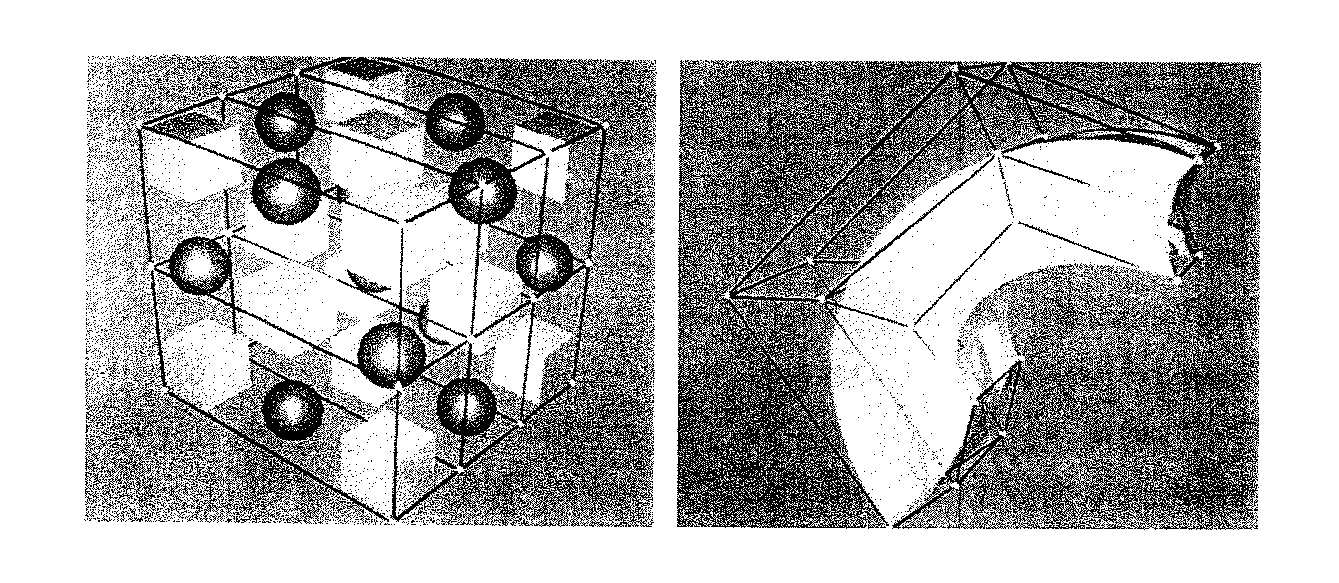
SederbergおよびParryは、立方体または円筒などの標準的な幾何形態のグリッド点の格子に物体を埋め込むことによって、規則的な変形(固体のR3からR2への写像)に対する手法を一般化した(非特許文献1)。グリッドのノードの操作によって、3変数テンソル積ベルンシュタイン多項式の助けを得て、グリッドの内部の空間に対する変形が誘導される。これらの変形は、物体を形成する基礎になるグラフィックス・プリミティブを変換する。SederbergおよびParryは、FFDのよい物理的類似を与えた。「変形が望まれる1つまたは複数の物体が組み込まれた透明で柔軟なプラスティックの平行六面体を検討されたい。物体も柔軟であると考えられ、その結果、物体は、その周囲のプラスティックに似た形で変形する」(非特許文献9)。 Sederberg and Parry generalized the approach to regular deformations (solid R 3 to R 2 mapping) by embedding objects in a grid of standard geometric grid points such as cubes or cylinders ( Non-patent document 1). Manipulation of the nodes of the grid induces deformations to the space inside the grid with the help of the three-variable tensor product Bernstein polynomial. These transformations transform the underlying graphics primitives that form the object. Sederberg and Parry gave a good physical similarity to FFD. “Consider a transparent and flexible plastic parallelepiped that incorporates one or more objects that are desired to be deformed. The object is also considered flexible, so that the object resembles the surrounding plastic. It deforms in shape "(Non-Patent Document 9).
既に指摘したように、FFDの最初のステップは、囲む平行六面体領域の局所座標系S、T、Uの固定である。ある基本的な線形代数の助けを得ると、平行六面体の各点Xを、次のように新しい座標系で表すことができる。 As already pointed out, the first step in FFD is fixing the local coordinate system S, T, U of the surrounding parallelepiped region. With the help of some basic linear algebra, each point X of the parallelepiped can be represented in a new coordinate system as follows:
X=X0+sS+tT+uU
FFDのアイデアは、囲むボリュームの変形が、そのボリュームの内部の変形を誘導することなので、次のステップは、平行六面体の制御点Pijkのグリッドの形成である。S方向でl個、T方向でm個、U方向でn個のグリッド点が、その制御点がグリッド点である3変数テンソル積ベルンシュタイン多項式の助けを得て、変形された囲むボリュームの定式化を可能にする。潜在的な設計最適化の自由パラメータを本質的に作る制御点の変形は、単に、その変位していない格子位置からPijkを移動することによって指定される。任意の点Xの変形された位置Xffdは、まず局所座標系でその(s,t,u)座標を計算し、次にベクトル値を有する3変数ベルンシュタイン多項式
The idea of FFD is that deformation of the surrounding volume induces deformation inside the volume, so the next step is the formation of a grid of parallelepiped control points Pijk . Formula for a deformed enclosing volume with the help of a three-variable tensor product Bernstein polynomial in which there are 1 grid point in the S direction, m grids in the T direction, and n grid points in the U direction, the control points of which are grid points. Make it possible. The deformation of the control point that essentially creates a free parameter for potential design optimization is specified simply by moving P ijk from its undisplaced grid position. The deformed position X ffd of an arbitrary point X is first calculated in the local coordinate system with its (s, t, u) coordinates, and then with a three-variable Bernstein polynomial having vector values
拡張型自由形状変形(EEFD)
Sederberg他によって導入された基本的な自由形状変形の概念を、より高度な柔軟性に関して改善するために、Coquillartは、拡張型自由形状変形(Extended Free Form Deformation:EEFD)と呼ばれる方法を開発した(非特許文献1)。この方法では、標準的な自由形状変形の制御点の平行六面体ボリュームという制限的要件と異なって、任意の制御ボリュームの使用が可能である。この変更のゆえに、物体を変形する手順が、適合されなければならず、数学的基礎が、Bスプラインに切り替えられなければならなかった。これは、主に、下で短く説明する3つのステップに分かれる。
Expandable free form deformation (EEFD)
In order to improve the basic free-form deformation concept introduced by Sederberg et al. With regard to a higher degree of flexibility, Coquillart has developed a method called Extended Free Form Deformation (EEFD) ( Non-patent document 1). This method allows the use of any control volume, unlike the restrictive requirement of a parallel hexahedral volume for standard freeform deformation control points. Because of this change, the procedure for deforming the object had to be adapted and the mathematical basis had to be switched to a B-spline. This is mainly divided into three steps which are briefly described below.
まず、物体全体または物体のうちで変形について対象とされている部分のいずれかを囲む制御点の格子(lattice)を構成しなければならない。第2ステップで、幾何座標を、格子のパラメータ空間に変形しなければならず、これを、「フリージング(freezing)」とも呼ぶ。物体のフリージングによって、スプライン・パラメータ空間での幾何形態のu、v、およびw座標が計算される。これは通常、最も高速の手法である見込みがあるニュートン近似によって行われるが、類似する傾きに基づく方法または進化的最適化(evolutionary optimisation)によって行うこともできる。u、v、およびw座標をうまく計算した後に、制御点を所望の位置に移動し、表面または固体のx、y、およびz座標を更新することによって、変形を適用することができる。したがって、Bスプライン式を、制御点の新しい空間座標を使用して解かなければならない。この方法は、幾何モデルが固体と等しいか、助変数方程式または暗黙の式によって定義される場合にも有効である。
本発明の目的は、改善された最適化技法を提案することである。 The object of the present invention is to propose an improved optimization technique.
この目的は、独立請求項の特徴によって達成される。従属請求項は、さらに、本発明の中心概念を展開するものである。本発明は、本発明による表現として自由形状変形を使用する進化的計算(Evolutionary Computation)を提案する。 This object is achieved by the features of the independent claims. The dependent claims further develop the central concept of the invention. The present invention proposes Evolutionary Computation using free-form deformation as representation according to the present invention.
自由形状変形と進化的計算の組合せは、本発明の1態様である。 The combination of freeform deformation and evolutionary computation is an aspect of the present invention.
自由形状変形での本発明のもう1つの態様によれば、変形が、問題に適合される。 According to another aspect of the invention with free form deformation, the deformation is adapted to the problem.
本発明のもう1つの態様によれば、Tスプラインが、自由形状変形の変換関数としての進化的計算と組み合わせて使用される。 According to another aspect of the invention, T-splines are used in combination with evolutionary computation as a transformation function for freeform deformation.
本発明のさらなる目的、特徴、および長所は、添付図面を参照して実施形態の次の説明に進む時に明白になる。 Further objects, features and advantages of the present invention will become apparent when proceeding to the next description of the embodiments with reference to the accompanying drawings.
進化的計算での(拡張型)自由形状変形
進化的最適化に関して、自由形状変形技法の適用は、特に、最適化されなければならない形態の幾何定義がかなり複雑である場合および/またはコストの高い計算流体力学(Computationally Fluid Dynamics:CFD)計算または有限要素法(Finite Element Method:FEM)計算を実行しなければならない場合に、多数の利益を特徴とする。自由形状変形と、最適化の目標にされているパラメータとの一体化は、形態幾何自体によって定義されるのではなく、格子の制御点によって定義される。その結果、設計者は、グローバル形態変更またはローカル形態変更の度合を選択することができる。
With regard to (expanded) free-form deformation evolutionary optimization in evolutionary computation, the application of free-form deformation techniques, especially when the geometric definition of the form that must be optimized is quite complex and / or expensive It features a number of benefits when it has to perform Computationally Fluid Dynamics (CFD) or Finite Element Method (FEM) calculations. The integration of freeform deformation and the parameters targeted for optimization is not defined by the morphological geometry itself, but by the control points of the grid. As a result, the designer can select the degree of global form change or local form change.
一般に、最適化ループを開始できるようになる前に、初期形態を格子に埋め込まなければならず、幾何形態をフリーズして、パラメータ空間内のu、v、およびw座標を入手しなければならない。これらの座標は、進化的最適化の設計評価ステップの前の遺伝子型−表現型写像(genotype-phenotype mapping)で主要な役割を演ずる。パラメータとしての制御点に基づいて、突然変異を適用することができ、適応度評価のためにシステムを準備することができる。したがって、新しい設計は、新しい制御点と結合されるフリーズされたu、v、w座標に基づくBスプライン式またはNurbs式を介して計算される。その後、設計を評価することができ、適応度の値が、各個々に割り当てられる。最後に、新しいパラメータを選択し、次世代の親を、選択された進化的アルゴリズムに従って決定する。 In general, before the optimization loop can be started, the initial form must be embedded in the grid and the geometry must be frozen to obtain the u, v, and w coordinates in the parameter space. These coordinates play a major role in the genotype-phenotype mapping prior to the evolutionary optimization design evaluation step. Based on the control points as parameters, mutations can be applied and the system can be prepared for fitness assessment. Thus, the new design is calculated via a B-spline or Nurbs formula based on the frozen u, v, w coordinates combined with the new control point. The design can then be evaluated and fitness values are assigned to each individually. Finally, new parameters are selected and the next generation parent is determined according to the selected evolutionary algorithm.
CFD評価またはFEM評価と結合された(拡張型)自由形状変形の効果
CFDまたはFEMと組み合わされた自由形状変形の多数の利益を理解するために、制御点の位置の変更が、格子のある空間領域に強い影響を有することを考慮しなければならない。サイズがたとえばスプラインのタイプ、スプライン次数、制御点の個数、ノットベクトル(knot vector)などによって定義されるこのボリューム全体が変形される、すなわち、このボリューム内で見つかる形態設計だけではなく、それを囲むすべてのものが変形される。CFD計算に関係する結果として、このボリューム内に位置するすべてのグリッド点も変形される。したがって、複雑な形態に関して、計算的にコストの高いメッシュ生成処理を省略することができる。というのは、自由形状変形が適用される時に、グリッドが、変形された形態に直接に適合されるからである。第2に、CFDに関して、時間のかかるCFD計算全体を繰り返すのではなく、既に解に収束している、以前の結果を使用することも可能である。
Effects of (extended) freeform deformation combined with CFD or FEM evaluation To understand the many benefits of freeform deformation combined with CFD or FEM, changing the position of the control points is a space with a grid. Consider having a strong impact on the area. This entire volume whose size is defined by eg spline type, spline order, number of control points, knot vector, etc. is deformed, ie it encloses not only the morphological design found in this volume Everything is transformed. As a result of the CFD calculation, all grid points located within this volume are also deformed. Therefore, a computationally expensive mesh generation process can be omitted for complex forms. This is because when freeform deformation is applied, the grid is directly adapted to the deformed form. Second, for CFD, it is possible to use previous results that have already converged to a solution, rather than repeating the entire time-consuming CFD calculation.
(拡張型)自由形状変形のパラメータ適応性
自由形状変形のこの拡張は、本発明のさらなる開発に特に有利である。すべての種類の最適化において、適用される表現の高い度合の柔軟性が有利である。設計者は、常に、検索空間とパラメータ最小化の間の適当なトレードオフを見つけることを強いられる。一方で、できる限り多くの設計を表現しなければならず、他方で、少数のパラメータを使用して最適化処理を高速化しなければならない。柔軟性に対するよい代替案は、適応的な表現によって提供される。その結果、最適化の開始時に、少数のパラメータを最適化するだけでよく、収束の過程で、パラメータの個数を増やすことができる。
(Extended) Freeform Deformation Parameter Adaptability This expansion of freeform deformation is particularly advantageous for further development of the invention. In all kinds of optimization, a high degree of flexibility of the applied representation is advantageous. Designers are always forced to find a suitable trade-off between search space and parameter minimization. On the one hand, as many designs as possible must be represented, and on the other hand, a small number of parameters must be used to speed up the optimization process. A good alternative to flexibility is provided by adaptive expressions. As a result, it is only necessary to optimize a small number of parameters at the start of optimization, and the number of parameters can be increased in the process of convergence.
自由形状変形は、設計処理で実際の形態を変更せずに、さらなる制御点を追加することによってノットベクトルを拡張する可能性を提供する。この事実は、進化的設計最適化において非常に重要である。非常に少数のパラメータだけを用いて最適化を開始し、必要な時にいつでも、新しい制御点を追加して、実際の最良の設計を失わずに形態に対する影響を拡張することができる。この表現のこれらの非常に前向きの特徴のほかに、制御点挿入に、1つの主要な不利益が付随する。新しい制御点を挿入しなければならない時に、必ず、2次元の場合に制御点の新しい列または行全体、3次元の場合に制御点の平面を制御点グリッドに導入する可能性だけが存在する。したがって、残念ながら、幾何学的理由から直接に望ましい場合に1つの制御点だけを挿入することは不可能であり、結果として、多数の余分な点を考慮に入れなければならない。この影響を最小にするために、Tスプラインという概念を、以下に説明する。Tスプラインとは、制御点の部分的な行または列だけを制御メッシュに挿入することを可能にする特別な種類の点ベースのBスプラインである。 Freeform deformation offers the possibility of extending the knot vector by adding additional control points without changing the actual form in the design process. This fact is very important in evolutionary design optimization. Optimization can be started with only a few parameters and new control points can be added whenever needed to extend the impact on the morphology without losing the actual best design. In addition to these very positive features of this representation, control point insertion is accompanied by one major disadvantage. Whenever a new control point has to be inserted, there is always the possibility of introducing a new column or row of control points in the two-dimensional case into the control point grid in the three-dimensional case. Thus, unfortunately, it is not possible to insert only one control point if it is directly desired for geometric reasons, and as a result a large number of extra points must be taken into account. In order to minimize this effect, the concept of T-splines will be described below. A T-spline is a special type of point-based B-spline that allows only partial rows or columns of control points to be inserted into the control mesh.
Tスプライン
したがって、Tスプラインの概念は、たとえばコンピュータ・グラフィックスに関して、既に既知の表現である。
T-splines Thus, the concept of T-splines is an already known representation, for example with respect to computer graphics.
従来技術から既知のTスプラインの導入
Tスプラインの概念は、グラフィカル設計の処理でのより高い柔軟性を達成するために、Sederberg他によって導入された(非特許文献1、非特許文献10)。Tスプラインは、基礎になるメッシュでの制御点の配置の指定に関する限りない利益を提供する、不均一Bスプライン曲面の一般化である。水平線および垂直線の各交点で定義される制御点の長方形グリッドを必要とするBスプライン曲面と異なって、Tメッシュの線は、グリッドの端で始まり、終わる必要はなく、T字型接続点で終わることができる(たとえば、図4)。その結果、制御点の総数が劇的に減る。この事実は、より柔軟で効率的な曲面設計を可能にするために1つまたは複数の追加制御点を挿入しなければならない場合に、さらに重要になる。Bスプライン曲面では、制御点の完全な新しい行および/または列を設けなければならないが、Tメッシュでは、ほとんどの場合に、少数の新しい点を追加するだけでよい。
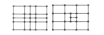
Introduction of T-splines known from the prior art The concept of T-splines was introduced by Sederberg et al. (Non-Patent Document 1, Non-Patent Document 10) in order to achieve greater flexibility in the processing of graphical designs. T-splines are a generalization of non-uniform B-spline surfaces that offer unlimited benefits for specifying control point placement in the underlying mesh. Unlike B-spline surfaces that require a rectangular grid of control points defined at each intersection of horizontal and vertical lines, T-mesh lines do not need to start and end at the edges of the grid, but at T-shaped connection points. Can end (eg, FIG. 4). As a result, the total number of control points is dramatically reduced. This fact becomes even more important when one or more additional control points must be inserted to allow a more flexible and efficient curved surface design. For B-spline surfaces, complete new rows and / or columns of control points must be provided, whereas for T-mesh, only a few new points need be added in most cases.
ノット挿入(knot insettion)の手順について、Sederberg他は、後で詳細に説明するローカル洗練アルゴリズム(local refinement algorithm)を開発し、次いで、「Tスプライン単純化(T-spline Simplification)」と呼ばれる、余分な制御点を除去する概念を開発した。除去アルゴリズムの適用によって、設計形態がBスプラインを介して定義されている場合に必要な制御点の総数を減らすことが可能になる。 For the knot insettion procedure, Sederberg et al. Developed a local refinement algorithm, described in detail later, and then called an extra “T-spline Simplification”. Developed a concept to eliminate various control points. Application of the removal algorithm makes it possible to reduce the total number of control points required when the design form is defined via B-splines.
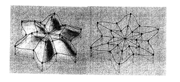
図5に、NURBSモデルのTスプラインへの変換の効果を示す。モデル化された頭の制御点の総数は、4712個から1109個に減り、女性の場合に10305個から3955個に減っている。その結果、設計者は、モデルに対するより効率的な制御を得、単一の制御点の位置の移動が、形態に対するより密接な影響を有する。さらに、Tスプラインの概念は、2次元での曲面モデリングに有効であるだけではなく、他の次元およびTスプラインの任意トポロジ版であるT−NURCC(Non-Uniform Rational Catmull-Clark Surface、非一様有理式カットマル−クラーク局面)に簡単に拡張することができる(非特許文献1、非特許文献8、非特許文献10)。 FIG. 5 shows the effect of conversion of the NURBS model to a T-spline. The total number of modeled head control points is reduced from 4712 to 1109, and from 10305 to 3955 for women. As a result, the designer has more efficient control over the model, and movement of the position of a single control point has a closer impact on the morphology. Furthermore, the concept of T-splines is not only effective for surface modeling in two dimensions, but is also an arbitrary topology version of T-NURCC (Non-Uniform Rational Catmull-Clark Surface, non-uniformity). It can be easily extended to (Rational Cut-Mar-Clark aspect) (Non-Patent Document 1, Non-Patent Document 8, Non-Patent Document 10).
Tスプラインの数学的定義および規則
Tスプラインは、Sederberg他(非特許文献10)によって導入されたいわゆる点ベースBスプライン(point based B-splines、PBスプライン)から導き出すことができる。PBスプラインは、制御点の組と、2次元で制御点ごとのノットベクトルの対によって定義される。結果の面の点を計算するために、次の式を解かなければならない。
Bi(s,t)は、ブレンディング関数であり、次式にように定義される。 B i (s, t) is a blending function and is defined as follows.
Bi(s, t)=N[si0, si1, si2, si3, si4](s)N[ti0, ti1, ti2, ti3, ti4](t)
N[si0, si1, si2, si3, si4](s)およびN[ti0, ti1, ti2, ti3, ti4](t)は、それぞれ、一般形状で次式によって与えられる3次Bスプライン基底関数である。
N [s i0 , s i1 , s i2 , s i3 , s i4 ] (s) and N [t i0 , t i1 , t i2 , t i3 , t i4 ] (t) are respectively general shapes, Is a cubic B-spline basis function given by
uiは、ノットベクトルのノットであり、pは、スプラインの次数を定義する。Biの計算のために、基底関数式を、短いノットベクトルsi=[si0, si1, si2, si3, si4]およびti=[ti0, ti1, ti2, ti3, ti4]を使用して評価しなければならない。このベクトルのそれぞれが、制御点Piに直接に接続されている。重みwiは、自由に選択することができる。すべてのwiが1.0である場合に、PBスプライン式は次のように単純になる。
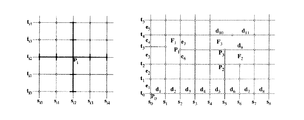
一般的に定義されたPBスプラインと対照的に、Tスプラインは、制御点の位置に対するある順序を定義する、いわゆるTメッシュによって構成される。Tメッシュの例を、図6に示す。 In contrast to the generally defined PB splines, T splines are constituted by so-called T meshes that define a certain order for the position of the control points. An example of a T mesh is shown in FIG.
このメッシュは、制御点Piに密接に接続されるノットベクトルの定義に重要である。Tメッシュが満足しなければならない次の要件が定式化されている。 This mesh is important for the definition of the knot vectors which are closely connected to the control point P i. The following requirements are formulated that the T-mesh must satisfy:
1.「すべての面の1側面に沿ったすべてのノット間隔(knot interval)の合計は、対向する側面のノット間隔の合計と等しくなければならない」。ノット間隔は、2つのノットの間の差と等しく、したがって、たとえば図6ではdiおよびeiである。 1. “The sum of all knot intervals along one side of all sides must be equal to the sum of the knot intervals on opposite sides.” The knot interval is equal to the difference between the two knots, and thus, for example, d i and e i in FIG.
2.2つのT字交差点は、接続の後に新しい面が各対向する側面に等しいノットベクトルの合計を有する場合に限って接続されなければならない(非特許文献8)。 2. Two T-shaped intersections must be connected only after connection, if the new surface has a sum of knot vectors equal to each opposing side surface (Non-Patent Document 8).
ノットベクトルsiおよびtiの定義は、ノット間隔に基づき、Bスプライン曲面の計算に必要な定義と全く異なる。これは、(非特許文献8)でルール1として示されている。 Definition of knot vectors s i and t i is based on knot intervals, quite different from the definitions required for the calculation of the B-spline surface. This is shown as rule 1 in (Non-Patent Document 8).
「パラメータ空間内の光線R(□)=(si2+□,t2)を検討されたい。すると、si3およびsi4は、その光線が交差する最初の2つのs辺のs座標である。s辺とは、定数sの垂直線分を意味する。siおよびtiの他のノットは、同様の形で見つかる」。すべてのノットベクトルが判定されたならば、Tスプラインを計算することができる。
ノット挿入−ローカル洗練アルゴリズム
Tスプラインの主要な利益の1つが、制御点の新しい行または列全体を挿入する必要なしに、Tメッシュ内の任意の位置に新しい制御点を挿入する可能性である。Sederberg他は、成功したノット挿入に関するルールおよびアルゴリズムを含む手順を開発した。挿入処理は、トポロジ・フェーズおよびジオメトリ・フェーズと呼ばれる2フェーズで行われる。トポロジ・フェーズでは、追加して挿入されなければならない制御点を識別し、ジオメトリ・フェーズでは、新しいTメッシュの新しい座標および重みを計算する。
Knot Insertion— One of the main benefits of the local refinement algorithm T-spline is the possibility of inserting new control points anywhere in the T mesh without having to insert a new row or column of control points. Sederberg et al. Developed a procedure that includes rules and algorithms for successful knot insertion. The insertion process is performed in two phases called a topology phase and a geometry phase. The topology phase identifies additional control points that must be inserted, and the geometry phase calculates new coordinates and weights for the new T-mesh.
Sederberg他(非特許文献8)は、挿入処理中に発生する可能性があり、追加制御点を挿入することによって訂正されなければならない3つの可能な違反を示した。 Sederberg et al. (8) have shown three possible violations that can occur during the insertion process and that must be corrected by inserting additional control points.
「違反1:ブレンディング関数(blending function)が、現在のTメッシュについてルール1によって指定されるノットを含まない。 “Violation 1: The blending function does not contain the knot specified by rule 1 for the current T-mesh.
違反2:ブレンディング関数が、現在のTメッシュについてルール1によって指定されていないノットを有する。 Violation 2: The blending function has knots not specified by rule 1 for the current T-mesh.
違反3:制御点が、それに関連するブレンディング関数を有しない。」
まず、すべての制御点を、より多くの制御が望まれる位置に挿入する。グリッド検査を行い、違反が発生している場合に追加の点を挿入する。すべての違反を解決した後に、新しい座標を、線形変換によって計算する。
Violation 3: The control point does not have a blending function associated with it. "
First, all control points are inserted at locations where more control is desired. Perform a grid inspection and insert additional points if violations occur. After resolving all violations, new coordinates are calculated by linear transformation.
本発明による適応表現
Tスプラインの概念と進化的最適化の組合せが、本発明のさらなる態様である。
The combination of the adaptive representation T-spline concept and evolutionary optimization according to the present invention is a further aspect of the present invention.
進化的最適化でのTスプライン
上で既に指摘したように、表現の適応的挙動は、最適化問題に関して非常に重要である。パラメータの個数をできる限り少なく保ち、同時にさまざまな形態設計を保証するように努めなければならない。Tスプラインは、設計最適化のこの要件に関する非常によいトレードオフを提供する。一般に、パラメータは、Tメッシュの制御点に対してセットされる。したがって、非常に少数の制御点から開始し、最適化の過程で、制御点を任意の位置に追加して、分解能を高めることができる。したがって、この表現を適用することによって、Tスプラインの高い柔軟性を使用して、制御点を必要な場所に直接に位置決めして、それまでの最善の設計を保ちながら幾何形態に対する最大の影響を達成することができる。これは、ほとんどの場合に、ごく少数の制御点の追加になるので、パラメータの個数が、できる限り少なく保たれる。これは、非常に良い形で最適化に影響する。
As already pointed out on T-splines in evolutionary optimization, the adaptive behavior of the representation is very important with respect to optimization problems. Efforts must be made to keep the number of parameters as small as possible while at the same time ensuring various form designs. T-splines provide a very good tradeoff for this requirement of design optimization. In general, parameters are set for control points of the T mesh. Therefore, it is possible to start from a very small number of control points and add control points to arbitrary positions in the process of optimization to increase the resolution. Therefore, by applying this representation, the high flexibility of the T-spline is used to position the control points directly where they are needed to maximize the impact on the geometry while maintaining the best design so far. Can be achieved. This almost always adds a very small number of control points, so the number of parameters is kept as small as possible. This affects the optimization in a very good way.
変換のパラメータが変更の自由度を決定するという事実に起因して、パラメータを、選択されたパラメータによって必要な変更を実行できる形でセットしなければならない。どの種類の最適化の場合でも、「必要な変更」は、事前にはわからず、経験に基づいてのみ知られる可能性がある。一般に自由度を高めるために、自由形状変形の場合に制御点の個数を単純に増やすことができる。これは、制御点の影響をよりローカルにし、設計に対するグローバル変更は、さまざまな制御点を同時に変更しなければならないので、実現がより困難になる。さらに、拘束付き変形の場合に、変更の自由と、制御点の個数または行列Mの次元の変更による最適化の次元数の間にトレードオフがある。この関係は、スプラインを使用する線または面の表現でも観察することができる。 Due to the fact that the parameters of the transformation determine the degree of freedom of change, the parameters must be set in such a way that the necessary changes can be performed by the selected parameters. For any kind of optimization, the “necessary changes” are not known in advance and may only be known based on experience. In general, in order to increase the degree of freedom, the number of control points can be simply increased in the case of free-form deformation. This makes control point effects more local and global changes to the design are more difficult to implement because the various control points must be changed simultaneously. Furthermore, in the case of constrained deformation, there is a trade-off between freedom of change and the number of dimensions for optimization by changing the number of control points or the dimensions of the matrix M. This relationship can also be observed in line or surface representations using splines.
上で説明したTスプラインの特性が、その開発の理由である。たとえばNURBS面スプラインによって面を表現することによって、単一の制御点の追加が、表現によって与えられる拘束を満足するだけのために、追加制御点の行または列全体の追加を必要とする。同一のことが、別の変更された設計への設計の変換を定義する自由形状変形方法に適用された時にもあてはまる。 The characteristics of the T-spline described above are the reason for its development. For example, by representing a surface with a NURBS surface spline, the addition of a single control point requires the addition of a whole row or column of additional control points only to satisfy the constraints imposed by the representation. The same applies when applied to a freeform deformation method that defines the transformation of a design into another modified design.
自由形状変形の既存の方法は、制御点のメッシュを定義することを必要とし、これは、設計の間の変換関数を定義する。この自由形状変形の既存方法に対する拡張が、制御点の自動追加または自動除去である。この方法を用いると、設計の最適化中の変換関数の変更を変更できるようになる。所与の変換関数が、十分に高い自由度をもたらさない場合に、制御点を、制御点の既存の組に追加することができる。この追加に起因して、より高い自由度が、変換関数に存在し、所与の品質尺度に関して設計をさらに改善できるより詳細な変形が可能になる。 Existing methods of freeform deformation require defining a mesh of control points, which defines a transformation function between designs. An extension to this existing method of freeform deformation is the automatic addition or removal of control points. Using this method, it is possible to change the transformation function during design optimization. Control points can be added to an existing set of control points if a given transformation function does not provide a sufficiently high degree of freedom. Due to this addition, a higher degree of freedom exists in the transformation function, allowing for more detailed variations that can further improve the design for a given quality measure.
スプライン(たとえば、面スプライン)に新しい制御点を導入する時に、所与の面の近似の場合に新しい制御点の最適位置を決定するさまざまな方法が存在する。新しい制御点の最適位置を見つけるためのローカル近似方法およびグローバル近似方法が存在する。しかし、これらの方法は、ローカル品質尺度が存在する場合に限って適用可能である。このローカル品質尺度が存在しない時には、これらの方法を適用することができない。これは、たとえば、表された機体の空気力学特性に基づく品質尺度にあてはまる。たとえば、タービン・ブレードの最適化の場合に、非常にしばしば、圧力損失が、品質尺度として使用される。この圧力損失は、設計の本体全体に依存し、追加制御点を挿入しなければならなくなる前に判定することができない。 When introducing a new control point into a spline (eg, a surface spline), there are various ways to determine the optimal position of the new control point for a given surface approximation. There are local and global approximation methods for finding the optimal position of a new control point. However, these methods are applicable only when a local quality measure exists. These methods cannot be applied when this local quality measure does not exist. This applies, for example, to a quality measure based on the aerodynamic characteristics of the represented airframe. For example, in the case of turbine blade optimization, very often pressure loss is used as a quality measure. This pressure loss depends on the entire body of the design and cannot be determined before additional control points have to be inserted.
この場合に、変換関数の追加パラメータの導入は、表現の追加の突然変異演算子(mutation operator)によって実現することができる。ランダムな制御点が、変換関数を表すスプラインに追加される。この変更された表現が、進化の既知の処理を受ける。追加制御点が、変換関数の前向きの変動を可能にするという意味で有益である場合に限って、これらが、進化の処理中に選択される。したがって、自由形状変形の所与の方法、制御点の導入の方法、および進化的計算の組合せが、自由形状変形に使用される変換関数を実際の最適化の必要に適合させる洗練された優雅な手法をもたらす。 In this case, the introduction of additional parameters of the transformation function can be realized by an additional mutation operator of the representation. Random control points are added to the spline that represents the transformation function. This altered representation is subjected to a known process of evolution. These are selected during the evolution process only if additional control points are beneficial in the sense of allowing forward variation of the transformation function. Therefore, the combination of a given method of freeform deformation, the method of introducing control points, and evolutionary computations is a refined and elegant way to adapt the transformation function used for freeform deformation to the actual optimization needs. Bring a method.
説明された方法によって変更される変換関数としてスプライン関数を使用する既述の方法が、特殊な必要に対する処理中の最適化の自由を高める洗練された優雅な方法である場合であっても、表現の主な短所はまだ存在する。制御点の導入は、表現の拘束を満足するだけのための複数の他の制御点の導入を必要とする。 Even if the described method of using a spline function as a transformation function modified by the described method is a sophisticated and graceful way to increase the freedom of in-process optimization for special needs The main disadvantages still exist. The introduction of control points requires the introduction of multiple other control points only to satisfy the expression constraints.
既に説明したように、Tスプラインは、面の表現の場合にこの問題を解決する。NurbsスプラインではなくTスプラインを使用すると、その場合の単一の追加制御点の導入が可能になる。 As already explained, T-splines solve this problem in the case of surface representation. The use of T-splines instead of Nurbs splines allows the introduction of a single additional control point in that case.
面モデリングと同一の形で、Tスプラインの使用は、自由形状変形の制御点追加中の問題を解決することができる。拡張型自由形状変形の場合と同一の形で、新しい制御点の導入を、追加の突然変異演算子によって実現することができる。追加の突然変異演算子は、変換のパラメータの代わりに変換の表現を同一の形で変更する。追加制御点の導入に関して最適の位置の選択を可能にする機構は、既に説明したものと同一である。相違と利益は、この方法が、変換関数のローカル拡張を可能にすることである。 In the same way as surface modeling, the use of T-splines can solve the problem of adding freeform deformation control points. The introduction of new control points can be realized with additional mutation operators in the same way as in the case of the extended freeform deformation. Additional mutation operators change the transformation representation in the same way instead of the transformation parameters. The mechanism that allows the selection of the optimum position for the introduction of additional control points is the same as already described. The difference and benefit is that this method allows local extension of the transformation function.
要約すると、説明した方法は、変換関数によって変更される基本設計を使用する設計の既知の表現に基づく。自由形状変形技法の場合に、変換関数は、設計が定義される空間を、新しい変更された設計が定義される第2空間に変換するスプライン関数によって定義される。設計処理中に、スプライン関数のパラメータが、変換関数のパラメータを決定する。進化戦略を使用している間に、スプライン関数のパラメータは、それと同時に、最適化アルゴリズムが働くパラメータを決定する。変換関数を所与の問題および必要な変換に最適に適合させるために、制御点の導入および削除を可能にする突然変異演算子が提案される。進化戦略での標準的な突然変異演算子ではなく、この突然変異演算子は、問題/設計の表現を操作する。 In summary, the described method is based on a known representation of a design that uses a basic design that is modified by a transformation function. In the case of free-form deformation techniques, the transformation function is defined by a spline function that transforms the space in which the design is defined into a second space in which the new modified design is defined. During the design process, the parameters of the spline function determine the parameters of the transformation function. While using the evolution strategy, the parameters of the spline function at the same time determine the parameters on which the optimization algorithm works. In order to best fit the transformation function to a given problem and the required transformation, mutation operators are proposed that allow the introduction and removal of control points. Instead of the standard mutation operator in evolution strategies, this mutation operator manipulates the problem / design representation.
上の方法にあてはまる短所は、基礎になるスプライン記述の使用によって導入される拘束であり、これは、単一のパラメータの導入が多数の点の導入を必要にすることである。この問題に対する解決策は、スプライン曲面の表現に関して説明され、Tスプラインと呼ばれる。本明細書で、変換関数としてのこの特殊なスプライン・タイプの超次元拡張を使用することを提案した。この特殊な変換関数のパラメータは、進化的計算の枠組みの中で使用することができ、表現を直接に扱う新しい突然変異演算子によって実際の最適化の特殊な必要に適合させることができる。 The disadvantage that applies to the above method is the constraint introduced by the use of the underlying spline description, which means that the introduction of a single parameter requires the introduction of multiple points. A solution to this problem is described in terms of spline surface representation and is called a T-spline. We have proposed here to use this special spline-type hyperdimensional extension as a transformation function. The parameters of this special transformation function can be used in the framework of evolutionary computation and can be adapted to the special needs of the actual optimization by new mutation operators that deal directly with expressions.
Claims (13)
前記設計は、変換関数を使用して変更され、前記設計が定義される空間を前記変更された設計が定義される別の空間に変換するスプライン関数によって前記変換関数が定義される自由形状変形が使用されており、
前記スプライン関数のパラメータは、前記変換関数のパラメータを変更し、
前記自由形状変形は、進化的計算の表現として使用される、方法。 A method of optimizing the design,
The design is modified using a transformation function, and a free-form deformation in which the transformation function is defined by a spline function that transforms the space in which the design is defined into another space in which the altered design is defined. Used,
The parameter of the spline function changes the parameter of the conversion function,
The method, wherein the free-form deformation is used as a representation of evolutionary computation.
進化的計算は、遺伝的アルゴリズムである、
請求項1に記載の方法。 Evolutionary computation is an evolutionary strategy, or evolutionary computation is a genetic algorithm,
The method of claim 1.
進化的計算は、遺伝的アルゴリズムである、
請求項6に記載の方法。 Evolutionary computation is an evolutionary strategy, or evolutionary computation is a genetic algorithm,
The method of claim 6.
進化的計算は、遺伝的アルゴリズムである、
請求項8に記載の方法。 Evolutionary computation is an evolutionary strategy, or evolutionary computation is a genetic algorithm,
The method of claim 8.
進化的計算は、遺伝的アルゴリズムである、
請求項10に記載の方法。 Evolutionary computation is an evolutionary strategy, or evolutionary computation is a genetic algorithm,
The method of claim 10.
A computer program for performing the method according to any of claims 1 to 12, when executed on a computing device.
Applications Claiming Priority (2)
| Application Number | Priority Date | Filing Date | Title |
|---|---|---|---|
| EP04030832 | 2004-12-27 | ||
| EP05021063.2A EP1675068B1 (en) | 2004-12-27 | 2005-09-27 | Evolutionary optimisation and free form deformation |
Publications (1)
| Publication Number | Publication Date |
|---|---|
| JP2006185444A true JP2006185444A (en) | 2006-07-13 |
Family
ID=35486248
Family Applications (1)
| Application Number | Title | Priority Date | Filing Date |
|---|---|---|---|
| JP2005369232A Pending JP2006185444A (en) | 2004-12-27 | 2005-12-22 | Evolutionary optimization method and free form deformation method |
Country Status (3)
| Country | Link |
|---|---|
| US (1) | US7609262B2 (en) |
| EP (1) | EP1675068B1 (en) |
| JP (1) | JP2006185444A (en) |
Cited By (1)
| Publication number | Priority date | Publication date | Assignee | Title |
|---|---|---|---|---|
| JP2011133930A (en) * | 2009-12-22 | 2011-07-07 | Fujitsu Ltd | Shape optimization program, method and device |
Families Citing this family (9)
| Publication number | Priority date | Publication date | Assignee | Title |
|---|---|---|---|---|
| DE602006002958D1 (en) * | 2006-03-27 | 2008-11-13 | Honda Res Inst Europe Gmbh | Evolutionary direct manipulation of free-form deformation representations for design optimization |
| US20080162090A1 (en) * | 2006-12-27 | 2008-07-03 | Ernest Clay Perry | System, methods, and computer readable media, for product design using t-spline deformation |
| US20080275677A1 (en) * | 2007-03-19 | 2008-11-06 | Optimal Solutions Software, Llc | System, methods, and computer readable media, for product design using coupled computer aided engineering models |
| JP4659060B2 (en) * | 2008-04-21 | 2011-03-30 | 株式会社日立製作所 | Shape model creation device and shape fitting optimization processing method |
| US8666119B1 (en) * | 2011-11-29 | 2014-03-04 | Lucasfilm Entertainment Company Ltd. | Geometry tracking |
| US9311755B2 (en) * | 2012-11-29 | 2016-04-12 | Microsoft Technology Licensing, Llc. | Self-disclosing control points |
| EP2763058B1 (en) * | 2013-01-30 | 2021-10-20 | Honda Research Institute Europe GmbH | Optimizing the design of physical structures/objects |
| GB201617666D0 (en) * | 2016-10-19 | 2016-11-30 | Rolls Royce Plc | Optimization of an automatically meshable shapes |
| CN108492372B (en) * | 2018-01-15 | 2020-04-03 | 哈尔滨工业大学(威海) | A Shape Editing Method for B-spline Surfaces |
Citations (1)
| Publication number | Priority date | Publication date | Assignee | Title |
|---|---|---|---|---|
| JPH08115353A (en) * | 1994-10-18 | 1996-05-07 | Agency Of Ind Science & Technol | Method for deforming three-dimensional form displayed by computer |
Family Cites Families (3)
| Publication number | Priority date | Publication date | Assignee | Title |
|---|---|---|---|---|
| US5719794A (en) * | 1995-07-19 | 1998-02-17 | United States Of America As Represented By The Secretary Of The Air Force | Process for the design of antennas using genetic algorithms |
| US7987073B2 (en) * | 2003-04-04 | 2011-07-26 | Canon Kabushiki Kaisha | Method and apparatus of optimally designing a structure |
| WO2005001722A2 (en) * | 2003-06-25 | 2005-01-06 | Bae Systems Plc | Design optimisation of computationally intensive design problems |
-
2005
- 2005-09-27 EP EP05021063.2A patent/EP1675068B1/en not_active Expired - Fee Related
- 2005-12-13 US US11/302,686 patent/US7609262B2/en not_active Expired - Fee Related
- 2005-12-22 JP JP2005369232A patent/JP2006185444A/en active Pending
Patent Citations (1)
| Publication number | Priority date | Publication date | Assignee | Title |
|---|---|---|---|---|
| JPH08115353A (en) * | 1994-10-18 | 1996-05-07 | Agency Of Ind Science & Technol | Method for deforming three-dimensional form displayed by computer |
Cited By (1)
| Publication number | Priority date | Publication date | Assignee | Title |
|---|---|---|---|---|
| JP2011133930A (en) * | 2009-12-22 | 2011-07-07 | Fujitsu Ltd | Shape optimization program, method and device |
Also Published As
| Publication number | Publication date |
|---|---|
| EP1675068A1 (en) | 2006-06-28 |
| US7609262B2 (en) | 2009-10-27 |
| EP1675068B1 (en) | 2014-03-12 |
| US20060187219A1 (en) | 2006-08-24 |
Similar Documents
| Publication | Publication Date | Title |
|---|---|---|
| JP4662959B2 (en) | Evolutionary direct manipulation of freeform deformation representation for design optimization (EvolutionaryDirectManipulation) | |
| Jun et al. | A new curve-based approach to polyhedral machining | |
| JP4934789B2 (en) | Interpolation processing method and interpolation processing apparatus | |
| CN111581776B (en) | An isogeometric analysis method based on geometric reconstruction model | |
| CN105302974B (en) | A kind of real-time cutting simulation method of flexible article analyzed based on finite element and time-varying modal | |
| JP4564506B2 (en) | Evolutionary Design Optimization by Extended Direct Manipulation Method of Free Form Deformation (FreeForm Deformation) | |
| JP2023084699A (en) | Computer Aided Generative Design with Feature Thickness Control to Boost Manufacturing and Structural Performance | |
| EP1242978B1 (en) | Mesh generator for and method of generating meshes in an extrusion process | |
| JP3963334B2 (en) | Meshing method and apparatus | |
| US11334690B2 (en) | Method for transforming the computer-aided design model of an object | |
| EP1675068B1 (en) | Evolutionary optimisation and free form deformation | |
| Guo | Surface generation using implicit cubics | |
| Quadros et al. | 3 D discrete skeleton generation by wave propagation on PR-octree for finite element mesh sizing | |
| JPH1196400A (en) | Shape conversion method | |
| JP3770840B2 (en) | Method and system for generating and processing harmonized point networks | |
| KR20160058299A (en) | Apparatus and method for slicing and contour building | |
| JP7645484B2 (en) | Information processing method and information processing device | |
| CN104299265A (en) | Group behavior control technology under fluid environment influence | |
| Elloumi et al. | Towards a building techniques of a BREP model starting from a meshed surface | |
| JP2007172181A (en) | Design data generation apparatus and design data generation program | |
| JP2025037254A (en) | Method for modifying a 3D model by using partial sketches in an AR/VR environment - Patents.com | |
| Liu | Shell-element mesh generation of unconventional aircraft configurations for multidisciplinary structural analysis | |
| Shen et al. | A freeform shape optimization of complex structures represented by arbitrary polygonal or polyhedral meshes | |
| Zhong | Processing of 3D Unstructured Measurement Data for Reverse Engineering | |
| Hamann et al. | Optimal linear spline approximation of digitized models |
Legal Events
| Date | Code | Title | Description |
|---|---|---|---|
| A621 | Written request for application examination |
Free format text: JAPANESE INTERMEDIATE CODE: A621 Effective date: 20071019 |
|
| A131 | Notification of reasons for refusal |
Free format text: JAPANESE INTERMEDIATE CODE: A131 Effective date: 20110412 |
|
| A601 | Written request for extension of time |
Free format text: JAPANESE INTERMEDIATE CODE: A601 Effective date: 20110705 |
|
| A602 | Written permission of extension of time |
Free format text: JAPANESE INTERMEDIATE CODE: A602 Effective date: 20110708 |
|
| A521 | Request for written amendment filed |
Free format text: JAPANESE INTERMEDIATE CODE: A523 Effective date: 20110912 |
|
| A131 | Notification of reasons for refusal |
Free format text: JAPANESE INTERMEDIATE CODE: A131 Effective date: 20111025 |
|
| A521 | Request for written amendment filed |
Free format text: JAPANESE INTERMEDIATE CODE: A523 Effective date: 20120105 |
|
| A02 | Decision of refusal |
Free format text: JAPANESE INTERMEDIATE CODE: A02 Effective date: 20120221 |