JP2006192541A - Cutting method for pure iron material - Google Patents
Cutting method for pure iron material Download PDFInfo
- Publication number
- JP2006192541A JP2006192541A JP2005007910A JP2005007910A JP2006192541A JP 2006192541 A JP2006192541 A JP 2006192541A JP 2005007910 A JP2005007910 A JP 2005007910A JP 2005007910 A JP2005007910 A JP 2005007910A JP 2006192541 A JP2006192541 A JP 2006192541A
- Authority
- JP
- Japan
- Prior art keywords
- cutting
- tool
- pure iron
- iron material
- amount
- Prior art date
- Legal status (The legal status is an assumption and is not a legal conclusion. Google has not performed a legal analysis and makes no representation as to the accuracy of the status listed.)
- Pending
Links
- 238000005520 cutting process Methods 0.000 title claims abstract description 62
- XEEYBQQBJWHFJM-UHFFFAOYSA-N Iron Chemical compound [Fe] XEEYBQQBJWHFJM-UHFFFAOYSA-N 0.000 title claims abstract description 58
- 239000000463 material Substances 0.000 title claims abstract description 52
- 229910052742 iron Inorganic materials 0.000 title claims abstract description 29
- 238000000034 method Methods 0.000 title claims abstract description 15
- OKTJSMMVPCPJKN-UHFFFAOYSA-N Carbon Chemical compound [C] OKTJSMMVPCPJKN-UHFFFAOYSA-N 0.000 claims abstract description 7
- 229910052799 carbon Inorganic materials 0.000 claims abstract description 7
- 239000011195 cermet Substances 0.000 claims abstract description 6
- ATJFFYVFTNAWJD-UHFFFAOYSA-N Tin Chemical compound [Sn] ATJFFYVFTNAWJD-UHFFFAOYSA-N 0.000 claims description 4
- 238000000576 coating method Methods 0.000 claims description 4
- 239000002356 single layer Substances 0.000 claims description 4
- 229910010037 TiAlN Inorganic materials 0.000 claims description 3
- 229910018072 Al 2 O 3 Inorganic materials 0.000 claims description 2
- 229910052718 tin Inorganic materials 0.000 claims description 2
- 238000004519 manufacturing process Methods 0.000 abstract description 4
- 238000003908 quality control method Methods 0.000 abstract description 4
- 229910045601 alloy Inorganic materials 0.000 abstract description 2
- 239000000956 alloy Substances 0.000 abstract description 2
- 230000000694 effects Effects 0.000 abstract description 2
- 239000000126 substance Substances 0.000 abstract 1
- 238000005524 ceramic coating Methods 0.000 description 3
- 230000007423 decrease Effects 0.000 description 3
- 229910000976 Electrical steel Inorganic materials 0.000 description 2
- 229910000831 Steel Inorganic materials 0.000 description 2
- 239000010959 steel Substances 0.000 description 2
- CWYNVVGOOAEACU-UHFFFAOYSA-N Fe2+ Chemical compound [Fe+2] CWYNVVGOOAEACU-UHFFFAOYSA-N 0.000 description 1
- -1 cemented carbide Substances 0.000 description 1
- 239000011248 coating agent Substances 0.000 description 1
- 230000000593 degrading effect Effects 0.000 description 1
- 238000003754 machining Methods 0.000 description 1
- 239000000696 magnetic material Substances 0.000 description 1
- 230000014759 maintenance of location Effects 0.000 description 1
- 238000003466 welding Methods 0.000 description 1
Images

Landscapes
- Turning (AREA)
- Cutting Tools, Boring Holders, And Turrets (AREA)
- Physical Vapour Deposition (AREA)
Abstract
Description
この発明は、純鉄系材料の切削方法に係り、具体的には、炭素含有量が0.01%以下の純鉄系材料を切削加工するときの工具寿命を向上させることが可能な切削方法に関する。 The present invention relates to a cutting method of a pure iron material, and specifically, a cutting method capable of improving the tool life when cutting a pure iron material having a carbon content of 0.01% or less. About.
純鉄系材料は、磁気特性には優れる反面、切削加工時の負荷が高いため、とくに、近年の複雑形状化した部品などでの生産性や品質管理等の面での改善が望まれている。従来、電磁鋼板などの純鉄系材料では、電磁気特性は幾分低下させることになるが、炭素を極僅かに含有させることにより、被削性を改善する場合が多かった。ところが、磁気特性向上への要求がますます高まり、その結果、炭素を殆んど含有しない、磁気特性に優れた純鉄系材料への要望が強くなってきている。このため、この純鉄系材料についても被削性と磁気特性の両方を満足することが求められている。 Pure iron-based materials are excellent in magnetic properties, but have a high load during cutting. Therefore, improvements in productivity, quality control, etc. for parts with complex shapes in recent years are desired. . Conventionally, in pure iron-based materials such as electromagnetic steel sheets, the electromagnetic characteristics are somewhat lowered, but machinability is often improved by containing a very small amount of carbon. However, there has been an increasing demand for improvement in magnetic properties, and as a result, there has been a growing demand for pure iron-based materials that contain almost no carbon and have excellent magnetic properties. For this reason, this pure iron material is also required to satisfy both machinability and magnetic properties.
純鉄系材料、中でも電磁鋼板について、切削性や磁気特性に影響を及ぼす成分を規定すること、または、非金属介在物の形態を制御することなどにより、磁気特性を損なわずに被削性を改善した電磁鋼板が開示されている(例えば、特許文献1、2参照)。
前記純鉄系材料は一種の難削性材料であるため、切削工具としては、通常、超硬合金、サーメットまたはCBN焼結体などの硬質材料を母材としたものが用いられるが、この純鉄系材料を切削加工する場合でも、工具寿命は、製造コストや品質管理などの観点から重要である。工具寿命が短いと、工具交換頻度が高くなり、加工コストも必然的に高くなる。純鉄系材料の切削加工で、磁気特性を損なわずに、実用上満足できる工具寿命を得るためには、特許文献1、2に開示されたような被削材料自体の特性改善だけでは不十分で、切削加工を行う際の加工条件を適正に選択する必要がある。
Since the pure iron-based material is a kind of difficult-to-cut material, the cutting tool is usually made of a hard material such as cemented carbide, cermet or CBN sintered body. Even when cutting ferrous materials, the tool life is important from the viewpoint of manufacturing cost and quality control. When the tool life is short, the frequency of tool change is high, and the processing cost is inevitably high. In order to obtain a practically satisfactory tool life without degrading magnetic properties when cutting pure iron-based materials, it is not sufficient to improve the properties of the work material itself as disclosed in
そこで、この発明の課題は、純鉄系材料で、磁気特性を損なわずに、工具寿命を向上させることが可能な切削加工方法を提供することである。 Accordingly, an object of the present invention is to provide a cutting method capable of improving the tool life with a pure iron-based material without impairing magnetic properties.
前記の課題を解決するために、この発明では以下の構成を採用したのである。 In order to solve the above problems, the present invention employs the following configuration.
即ち、請求項1に係る純鉄系材料の切削方法は、炭素含有量が0.01wt%以下の純鉄系材料を、母材として硬質材料を用いた切削工具により切削する純鉄系材料の切削方法であって、前記切削工具のすくい角が7度から42度の範囲にあり、切削速度が150m/min以上であることを特徴とする。
That is, the pure iron-based material cutting method according to
本発明者らは、純鉄系材料の切削加工時の工具寿命の向上という観点から、工具摩耗量に及ぼす工具形状(すくい角)および切削速度の影響を検討したところ、後述するように、これらの加工条件がいずれも上記の範囲にあるときに、工具摩耗量が半減することを見出したのである。なお、上記切削速度は、より一層の工具摩耗量の低減の観点から、200m/min以上がより好ましい。 The present inventors examined the influence of the tool shape (rake angle) and the cutting speed on the amount of tool wear from the viewpoint of improving the tool life during cutting of pure iron-based materials. The present inventors have found that the amount of tool wear is halved when all the machining conditions are in the above range. The cutting speed is more preferably 200 m / min or more from the viewpoint of further reducing the amount of tool wear.
請求項2に係る純鉄系材料の切削方法は、前記硬質材料が超硬合金またはサーメットであり、この硬質材料の表面に、Al2O3、TiN、TiAlN、TiCN系のコーティングの中、いずれかのコーティングが単層または多層に施されていることを特徴とする。 In the method for cutting pure iron-based material according to claim 2, the hard material is cemented carbide or cermet, and any one of Al 2 O 3 , TiN, TiAlN, and TiCN-based coatings on the surface of the hard material. These coatings are characterized by being applied in a single layer or multiple layers.
上記のようなセラミックスコーティングを、例えば、PVDにより硬質材料を母材とする工具表面に施すことにより、耐摩耗性の向上に加えて、すくい面上への切り屑の付着や滞留を抑制して耐溶着性が向上するため、良好な切れ味がより長く維持され、工具摩耗量が低減する。前記コーティングの厚みは、1〜20μm程度とすることが望ましい。 For example, by applying the ceramic coating as described above to the tool surface using a hard material as a base material by PVD, in addition to improving wear resistance, the adhesion and retention of chips on the rake face can be suppressed. Since the welding resistance is improved, a good sharpness is maintained for a longer time, and the amount of tool wear is reduced. The thickness of the coating is preferably about 1 to 20 μm.
この発明によれば、延性が大きく、一種の難削材である純鉄系材料を切削するにあたり、工具摩耗量低減半減の観点から、主要な切削加工条件である工具のすくい角と切削速度を適正に選択できるため、磁気特性などの他の特性を損なわずに被削性が改善され、工具寿命が向上する。また、超硬合金やサーメットなどの硬質材料を母材とした表面にセラミックスコーティングを施した工具を用いて上記適正切削加工条件で切削を行うことにより、工具摩耗量の低減に寄与できる。このような適正な切削加工条件および切削工具の選択による工具摩耗量の低減により工具寿命が向上することで、工具交換頻度も少なくなり、生産性や製造コストおよび被削材の品質管理の面での改善効果が大きい。 According to the present invention, when cutting pure iron-based material, which has a high ductility and is a kind of difficult-to-cut material, the tool rake angle and cutting speed, which are the main cutting conditions, are reduced from the viewpoint of reducing tool wear by half. Since it can be selected appropriately, machinability is improved without impairing other characteristics such as magnetic characteristics, and the tool life is improved. Moreover, it can contribute to reduction of a tool wear amount by cutting on the said appropriate cutting process conditions using the tool which gave the ceramic coating to the surface which used hard materials, such as a cemented carbide alloy and a cermet, as a base material. The tool life is improved by reducing the amount of tool wear by selecting appropriate cutting conditions and cutting tools, so that the frequency of tool replacement is reduced, and in terms of productivity, manufacturing costs, and quality control of work materials. The improvement effect is great.
以下に、この発明の実施形態を添付の図1から図3に基づいて説明する。 Embodiments of the present invention will be described below with reference to the accompanying FIGS.
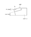
図1は、純鉄系材料の旋削加工に用いる工具形状を模式的に示したもので、工具1は、超硬合金またはサーメットなどの硬質材料の母材に、例えば、PVDにより、Al2O3、TiN、TiAlN、TiCN系のいずれかのセラミックスコーティングが単層または多層に施され、すくい角αが7度〜42度の範囲のいずれかの角度で形成され、ホルダー傾斜角βの工具ホルダー2に装着されている。そして、工具1を装着した工具ホルダー2が旋盤にセットされ、150m/min以上の切削速度で、より好ましくは200m/min以上の切削速度で、炭素含有量が0.01wt%以下の、電磁鋼板などの純鉄系材料が、通常の送り速度、例えば、0.1mm/revで切削される。以下に実施例について説明する。
FIG. 1 schematically shows a tool shape used for turning of a pure iron-based material. The
C≦0.01%、Si≦0.03%、0.2%≦Mn≦0.3%の純鉄系材料の直径80mmの丸棒を、切削速度を200m/minとし、表1に示すように、すくい角αの異なる工具1を工具ホルダー2に装着してそれぞれ旋削加工を行い、工具1のすくい面1aの摩耗幅を測定し、この測定値を切削長で除した値を工具摩耗量Wとした。なお、工具1は、超硬合金の母材にTiNを厚み10μmで単層コーティングしたものを用い、切り込み量を0.2mm、送り速度を0.1mm/revと、ホルダー傾斜角βを15度とした。
Table 1 shows a round bar with a diameter of 80 mm of a pure iron-based material with C ≦ 0.01%, Si ≦ 0.03%, 0.2% ≦ Mn ≦ 0.3%, with a cutting speed of 200 m / min. In this way, the

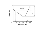
図2は、上記旋削加工による工具摩耗量Wを工具1のすくい角αに対してプロットしたものである。縦軸の工具摩耗量Wは、摩耗量が最大である、すくい角αが50度の場合の工具摩耗量Wmaxを1として、この工具摩耗量Wmaxに対する比率で示している。図2から、工具摩耗量Wmaxと摩耗量が最も少ないすくい角αが32度の場合の工具摩耗量Wminとの差(aで表示)の半分(bで表示)以下の工具摩耗量Wとなるすくい角αは、7度〜42度の範囲にある。この範囲ですくい角αを適切に選択すれば、工具摩耗量を半減できることがわかる。
FIG. 2 is a plot of the tool wear amount W by the turning process described above with respect to the rake angle α of the
実施例1(図2)から、工具摩耗量Wは、すくい角αがおよそ32度のときに最小となることから、実施例1の場合と同じ材質で、すくい角αが32度の工具1を工具ホルダー2に装着し、表2に示すように切削速度を変化させて、実施例1の場合と同じ純鉄系材料の旋削加工を行ない、前述のように工具摩耗量を測定した。なお、切り込み量、送り、ホルダー傾斜角βは実施例1の場合と同じである。
From Example 1 (FIG. 2), the amount of tool wear W is minimized when the rake angle α is approximately 32 degrees. Therefore, the
図3は、上記旋削加工による工具摩耗量Wを切削速度に対してプロットしたものである。縦軸の工具摩耗量Wは、摩耗量が最大である、切削速度が80m/minの場合の工具摩耗量Wmaxを1として、この工具摩耗量Wmaxに対する比率で示している。図2から、工具摩耗量Wmaxと摩耗量が最も少ない切削速度1000m/minの場合の工具摩耗量Wminとの差(aで表示)の半分(bで表示、b=a/2)以下の工具摩耗量Wとなる切削速度は、150m/min以上の範囲にある。この範囲で切削速度を適切に選択すれば、工具摩耗量を半減できることがわかる。なお、図3から、切削速度の上昇に伴い、工具摩耗量Wの降下がなだらかになり始める、およそ200mm/min以上の範囲の切削速度で、工具摩耗量が著しく低減する、即ち、工具摩耗量Wmaxと同Wminの差の1/4(a/4)以下になることがわかる。また、切削速度が1000m/min付近では、工具摩耗量の低下は殆んどみられなく、切削速度が高速化すると、切削面の摩擦抵抗の増加等による工具温度の上昇や仕上げ面の低下の虞があるため、切削速度の上限は2000m/min程度としておくことが望ましい。 FIG. 3 is a plot of the amount of tool wear W by the above-mentioned turning process against the cutting speed. The tool wear amount W on the vertical axis is shown as a ratio to the tool wear amount Wmax, where 1 is the tool wear amount Wmax when the wear amount is the maximum and the cutting speed is 80 m / min. FIG. 2 shows that the tool wear amount Wmax is less than half of the difference (indicated by a) and indicated by b (b = a / 2) between the tool wear amount Wmin and the cutting speed of 1000 m / min with the smallest wear amount. The cutting speed at which the wear amount is W is in the range of 150 m / min or more. It can be seen that if the cutting speed is appropriately selected within this range, the amount of tool wear can be halved. From FIG. 3, as the cutting speed increases, the tool wear amount W starts to gradually decrease, and the tool wear amount is remarkably reduced at a cutting speed in the range of about 200 mm / min or more, that is, the tool wear amount. It can be seen that the difference between Wmax and Wmin is ¼ (a / 4) or less. In addition, when the cutting speed is around 1000 m / min, there is almost no decrease in the amount of tool wear. When the cutting speed is increased, the tool temperature increases due to an increase in the frictional resistance of the cutting surface or the finish surface decreases. Therefore, the upper limit of the cutting speed is preferably about 2000 m / min.
なお、本発明に係る切削方法は、必ずしも、実施例1および実施例2に示したような旋削に限定するものではなく、切削加工全般に適用可能である。 The cutting method according to the present invention is not necessarily limited to turning as shown in the first and second embodiments, and can be applied to general cutting.
この発明は、純鉄系の磁性材料から各種電磁部品を製造する過程での切削工程で利用することができる。 The present invention can be used in a cutting process in the process of manufacturing various electromagnetic components from a pure iron-based magnetic material.
1・・・工具
1a・・・すくい面
2・・・工具ホルダー
DESCRIPTION OF
Claims (2)
The hard material is a cemented carbide or cermet, and any one of Al 2 O 3 , TiN, TiAlN, and TiCN coatings is applied to the surface of the hard material in a single layer or multiple layers. The cutting method of the pure iron-type material of Claim 1 characterized by these.
Priority Applications (1)
| Application Number | Priority Date | Filing Date | Title |
|---|---|---|---|
| JP2005007910A JP2006192541A (en) | 2005-01-14 | 2005-01-14 | Cutting method for pure iron material |
Applications Claiming Priority (1)
| Application Number | Priority Date | Filing Date | Title |
|---|---|---|---|
| JP2005007910A JP2006192541A (en) | 2005-01-14 | 2005-01-14 | Cutting method for pure iron material |
Publications (1)
| Publication Number | Publication Date |
|---|---|
| JP2006192541A true JP2006192541A (en) | 2006-07-27 |
Family
ID=36798993
Family Applications (1)
| Application Number | Title | Priority Date | Filing Date |
|---|---|---|---|
| JP2005007910A Pending JP2006192541A (en) | 2005-01-14 | 2005-01-14 | Cutting method for pure iron material |
Country Status (1)
| Country | Link |
|---|---|
| JP (1) | JP2006192541A (en) |
Citations (3)
| Publication number | Priority date | Publication date | Assignee | Title |
|---|---|---|---|---|
| JPH05331602A (en) * | 1992-05-29 | 1993-12-14 | Kawasaki Steel Corp | Non-oriented electrical steel sheet with excellent machinability |
| JPH10217008A (en) * | 1997-01-31 | 1998-08-18 | Kyocera Corp | Cutting insert |
| JP2005001024A (en) * | 2003-06-10 | 2005-01-06 | Tungaloy Corp | Throw-away tip |
-
2005
- 2005-01-14 JP JP2005007910A patent/JP2006192541A/en active Pending
Patent Citations (3)
| Publication number | Priority date | Publication date | Assignee | Title |
|---|---|---|---|---|
| JPH05331602A (en) * | 1992-05-29 | 1993-12-14 | Kawasaki Steel Corp | Non-oriented electrical steel sheet with excellent machinability |
| JPH10217008A (en) * | 1997-01-31 | 1998-08-18 | Kyocera Corp | Cutting insert |
| JP2005001024A (en) * | 2003-06-10 | 2005-01-06 | Tungaloy Corp | Throw-away tip |
Similar Documents
| Publication | Publication Date | Title |
|---|---|---|
| JP4739321B2 (en) | Replaceable cutting edge | |
| JP2005193376A (en) | Coated tool with long service life | |
| EP2576854B1 (en) | Coated cutting tool | |
| KR20130006666A (en) | Cutting tool | |
| JP3766003B2 (en) | Coated cutting tool | |
| EP3015205A1 (en) | Cutting insert, cutting tool, and production method for cut workpiece | |
| Kumar et al. | Comparative evaluation of performances of TiAlN-, AlCrN-and AlCrN/TiAlN-coated carbide cutting tools and uncoated carbide cutting tools on turning EN24 alloy steel | |
| JP2004345078A (en) | PVD coated cutting tool | |
| US20080050186A1 (en) | Cemented carbide inserts for milling of hard fe-based alloys more than 45 HRC | |
| JP2007260851A (en) | Surface coated cutting tool | |
| CN110730698B (en) | Surface-covered cutting tools | |
| JP4443177B2 (en) | Throwaway tip | |
| KR102353655B1 (en) | clad cutting tool | |
| JP2005199420A (en) | Hard film coated tool | |
| JP2009160692A (en) | Coated tool | |
| CN109576670B (en) | Hard coating film for cutting tool | |
| JP2006055950A (en) | Coated cutting tool | |
| JP3206972B2 (en) | Fine-grain cemented carbide | |
| JP4453902B2 (en) | Hard coating and hard coating tool | |
| KR20060042066A (en) | Cutting tool for metal machining | |
| JP4878808B2 (en) | Replaceable cutting edge | |
| CN113260475A (en) | Surface coated cutting tool | |
| JP2007136611A (en) | Amorphous carbon coated cutting tool and manufacturing method for it | |
| WO2006109457A1 (en) | Edge replacement cutter tip | |
| JP5094293B2 (en) | Cutting tools |
Legal Events
| Date | Code | Title | Description |
|---|---|---|---|
| A621 | Written request for application examination |
Effective date: 20070928 Free format text: JAPANESE INTERMEDIATE CODE: A621 |
|
| A131 | Notification of reasons for refusal |
Free format text: JAPANESE INTERMEDIATE CODE: A131 Effective date: 20100216 |
|
| A977 | Report on retrieval |
Effective date: 20100218 Free format text: JAPANESE INTERMEDIATE CODE: A971007 |
|
| A521 | Written amendment |
Effective date: 20100413 Free format text: JAPANESE INTERMEDIATE CODE: A523 |
|
| A131 | Notification of reasons for refusal |
Free format text: JAPANESE INTERMEDIATE CODE: A131 Effective date: 20100622 |
|
| A02 | Decision of refusal |
Free format text: JAPANESE INTERMEDIATE CODE: A02 Effective date: 20101019 |