JP2006192545A - Surface-coated cutting tool and manufacturing method thereof - Google Patents
Surface-coated cutting tool and manufacturing method thereof Download PDFInfo
- Publication number
- JP2006192545A JP2006192545A JP2005008085A JP2005008085A JP2006192545A JP 2006192545 A JP2006192545 A JP 2006192545A JP 2005008085 A JP2005008085 A JP 2005008085A JP 2005008085 A JP2005008085 A JP 2005008085A JP 2006192545 A JP2006192545 A JP 2006192545A
- Authority
- JP
- Japan
- Prior art keywords
- coating
- film
- cutting tool
- coated cutting
- aluminum oxide
- Prior art date
- Legal status (The legal status is an assumption and is not a legal conclusion. Google has not performed a legal analysis and makes no representation as to the accuracy of the status listed.)
- Withdrawn
Links
- 238000005520 cutting process Methods 0.000 title claims abstract description 68
- 238000004519 manufacturing process Methods 0.000 title claims abstract description 15
- 238000000576 coating method Methods 0.000 claims abstract description 157
- 239000011248 coating agent Substances 0.000 claims abstract description 152
- TWNQGVIAIRXVLR-UHFFFAOYSA-N oxo(oxoalumanyloxy)alumane Chemical compound O=[Al]O[Al]=O TWNQGVIAIRXVLR-UHFFFAOYSA-N 0.000 claims abstract description 63
- 238000000034 method Methods 0.000 claims abstract description 53
- 238000005229 chemical vapour deposition Methods 0.000 claims abstract description 44
- 238000005240 physical vapour deposition Methods 0.000 claims abstract description 32
- 239000000758 substrate Substances 0.000 claims abstract description 20
- 150000001875 compounds Chemical class 0.000 claims abstract description 14
- 230000003647 oxidation Effects 0.000 claims abstract description 13
- 238000007254 oxidation reaction Methods 0.000 claims abstract description 13
- 229910052782 aluminium Inorganic materials 0.000 claims abstract description 9
- 229910052710 silicon Inorganic materials 0.000 claims abstract description 9
- 230000000737 periodic effect Effects 0.000 claims abstract description 5
- 239000000463 material Substances 0.000 claims description 29
- 239000000919 ceramic Substances 0.000 claims description 19
- IJGRMHOSHXDMSA-UHFFFAOYSA-N Atomic nitrogen Chemical compound N#N IJGRMHOSHXDMSA-UHFFFAOYSA-N 0.000 claims description 16
- 229910052735 hafnium Inorganic materials 0.000 claims description 13
- 229910052726 zirconium Inorganic materials 0.000 claims description 13
- 239000002245 particle Substances 0.000 claims description 11
- QVGXLLKOCUKJST-UHFFFAOYSA-N atomic oxygen Chemical compound [O] QVGXLLKOCUKJST-UHFFFAOYSA-N 0.000 claims description 9
- 229910052760 oxygen Inorganic materials 0.000 claims description 9
- 239000001301 oxygen Substances 0.000 claims description 9
- OKTJSMMVPCPJKN-UHFFFAOYSA-N Carbon Chemical compound [C] OKTJSMMVPCPJKN-UHFFFAOYSA-N 0.000 claims description 8
- 229910052796 boron Inorganic materials 0.000 claims description 8
- 229910052799 carbon Inorganic materials 0.000 claims description 8
- 229910052757 nitrogen Inorganic materials 0.000 claims description 8
- ZOXJGFHDIHLPTG-UHFFFAOYSA-N Boron Chemical compound [B] ZOXJGFHDIHLPTG-UHFFFAOYSA-N 0.000 claims description 7
- 229910052804 chromium Inorganic materials 0.000 claims description 6
- 229910052719 titanium Inorganic materials 0.000 claims description 6
- 239000011195 cermet Substances 0.000 claims description 5
- 239000002131 composite material Substances 0.000 claims description 5
- 229910052720 vanadium Inorganic materials 0.000 claims description 4
- 229910052582 BN Inorganic materials 0.000 claims description 3
- PZNSFCLAULLKQX-UHFFFAOYSA-N Boron nitride Chemical compound N#B PZNSFCLAULLKQX-UHFFFAOYSA-N 0.000 claims description 3
- 229910000997 High-speed steel Inorganic materials 0.000 claims description 3
- 229910003460 diamond Inorganic materials 0.000 claims description 3
- 239000010432 diamond Substances 0.000 claims description 3
- 229910045601 alloy Inorganic materials 0.000 claims 1
- 239000000956 alloy Substances 0.000 claims 1
- 230000032798 delamination Effects 0.000 abstract description 5
- 239000010410 layer Substances 0.000 description 19
- PNEYBMLMFCGWSK-UHFFFAOYSA-N aluminium oxide Inorganic materials [O-2].[O-2].[O-2].[Al+3].[Al+3] PNEYBMLMFCGWSK-UHFFFAOYSA-N 0.000 description 16
- 238000005422 blasting Methods 0.000 description 11
- 230000000052 comparative effect Effects 0.000 description 9
- 230000000694 effects Effects 0.000 description 9
- 230000007423 decrease Effects 0.000 description 6
- 229910000831 Steel Inorganic materials 0.000 description 5
- 229910010037 TiAlN Inorganic materials 0.000 description 5
- 239000013078 crystal Substances 0.000 description 5
- 238000002635 electroconvulsive therapy Methods 0.000 description 5
- 239000002356 single layer Substances 0.000 description 5
- 239000010959 steel Substances 0.000 description 5
- 239000010936 titanium Substances 0.000 description 5
- XKRFYHLGVUSROY-UHFFFAOYSA-N Argon Chemical compound [Ar] XKRFYHLGVUSROY-UHFFFAOYSA-N 0.000 description 4
- 238000007733 ion plating Methods 0.000 description 4
- 239000000203 mixture Substances 0.000 description 4
- 229910018072 Al 2 O 3 Inorganic materials 0.000 description 3
- ATJFFYVFTNAWJD-UHFFFAOYSA-N Tin Chemical compound [Sn] ATJFFYVFTNAWJD-UHFFFAOYSA-N 0.000 description 3
- 238000005299 abrasion Methods 0.000 description 3
- 229910052751 metal Inorganic materials 0.000 description 3
- 239000002184 metal Substances 0.000 description 3
- XEEYBQQBJWHFJM-UHFFFAOYSA-N Iron Chemical compound [Fe] XEEYBQQBJWHFJM-UHFFFAOYSA-N 0.000 description 2
- 229910008482 TiSiN Inorganic materials 0.000 description 2
- 230000002411 adverse Effects 0.000 description 2
- 229910052786 argon Inorganic materials 0.000 description 2
- 230000006835 compression Effects 0.000 description 2
- 238000007906 compression Methods 0.000 description 2
- 239000007789 gas Substances 0.000 description 2
- 229910000765 intermetallic Inorganic materials 0.000 description 2
- QRXWMOHMRWLFEY-UHFFFAOYSA-N isoniazide Chemical compound NNC(=O)C1=CC=NC=C1 QRXWMOHMRWLFEY-UHFFFAOYSA-N 0.000 description 2
- VNWKTOKETHGBQD-UHFFFAOYSA-N methane Chemical compound C VNWKTOKETHGBQD-UHFFFAOYSA-N 0.000 description 2
- 238000003801 milling Methods 0.000 description 2
- 229910052758 niobium Inorganic materials 0.000 description 2
- HBMJWWWQQXIZIP-UHFFFAOYSA-N silicon carbide Chemical compound [Si+]#[C-] HBMJWWWQQXIZIP-UHFFFAOYSA-N 0.000 description 2
- 229910010271 silicon carbide Inorganic materials 0.000 description 2
- 238000004544 sputter deposition Methods 0.000 description 2
- 239000000126 substance Substances 0.000 description 2
- 238000006467 substitution reaction Methods 0.000 description 2
- 230000003746 surface roughness Effects 0.000 description 2
- 229910052715 tantalum Inorganic materials 0.000 description 2
- 238000003466 welding Methods 0.000 description 2
- 229910017109 AlON Inorganic materials 0.000 description 1
- UGFAIRIUMAVXCW-UHFFFAOYSA-N Carbon monoxide Chemical compound [O+]#[C-] UGFAIRIUMAVXCW-UHFFFAOYSA-N 0.000 description 1
- 229910052581 Si3N4 Inorganic materials 0.000 description 1
- 229910004298 SiO 2 Inorganic materials 0.000 description 1
- 229910010060 TiBN Inorganic materials 0.000 description 1
- 238000002441 X-ray diffraction Methods 0.000 description 1
- 229910052769 Ytterbium Inorganic materials 0.000 description 1
- GEIAQOFPUVMAGM-UHFFFAOYSA-N ZrO Inorganic materials [Zr]=O GEIAQOFPUVMAGM-UHFFFAOYSA-N 0.000 description 1
- 230000002159 abnormal effect Effects 0.000 description 1
- 238000000137 annealing Methods 0.000 description 1
- 229910002091 carbon monoxide Inorganic materials 0.000 description 1
- 229910010293 ceramic material Inorganic materials 0.000 description 1
- 239000011247 coating layer Substances 0.000 description 1
- 239000000470 constituent Substances 0.000 description 1
- PMHQVHHXPFUNSP-UHFFFAOYSA-M copper(1+);methylsulfanylmethane;bromide Chemical compound Br[Cu].CSC PMHQVHHXPFUNSP-UHFFFAOYSA-M 0.000 description 1
- 230000006378 damage Effects 0.000 description 1
- 238000000151 deposition Methods 0.000 description 1
- 238000010586 diagram Methods 0.000 description 1
- 238000005516 engineering process Methods 0.000 description 1
- -1 etc.) Inorganic materials 0.000 description 1
- 230000008020 evaporation Effects 0.000 description 1
- 238000001704 evaporation Methods 0.000 description 1
- 239000011521 glass Substances 0.000 description 1
- 238000009413 insulation Methods 0.000 description 1
- 238000001755 magnetron sputter deposition Methods 0.000 description 1
- 238000000691 measurement method Methods 0.000 description 1
- 238000001883 metal evaporation Methods 0.000 description 1
- 229910021645 metal ion Inorganic materials 0.000 description 1
- 238000012986 modification Methods 0.000 description 1
- 230000004048 modification Effects 0.000 description 1
- 229910003465 moissanite Inorganic materials 0.000 description 1
- 229910052750 molybdenum Inorganic materials 0.000 description 1
- 150000004767 nitrides Chemical class 0.000 description 1
- 239000000843 powder Substances 0.000 description 1
- 239000012495 reaction gas Substances 0.000 description 1
- HQVNEWCFYHHQES-UHFFFAOYSA-N silicon nitride Chemical compound N12[Si]34N5[Si]62N3[Si]51N64 HQVNEWCFYHHQES-UHFFFAOYSA-N 0.000 description 1
- MTPVUVINMAGMJL-UHFFFAOYSA-N trimethyl(1,1,2,2,2-pentafluoroethyl)silane Chemical compound C[Si](C)(C)C(F)(F)C(F)(F)F MTPVUVINMAGMJL-UHFFFAOYSA-N 0.000 description 1
- 229910052721 tungsten Inorganic materials 0.000 description 1
- 238000007740 vapor deposition Methods 0.000 description 1
- 229910052727 yttrium Inorganic materials 0.000 description 1
Images
Landscapes
- Cutting Tools, Boring Holders, And Turrets (AREA)
- Physical Vapour Deposition (AREA)
- Chemical Vapour Deposition (AREA)
Abstract
【課題】 高温時の耐酸化性に優れるとともに、靭性にも優れかつ被膜の層間剥離を生じることがない被膜を有する表面被覆切削工具およびその製造方法を提供すること。
【解決手段】 被膜は、化学蒸着法により形成される第1被膜と物理蒸着法により形成される第2被膜および第3被膜とを含み、第1被膜は、基材1と第2被膜との間に位置するものであって、α型酸化アルミニウムを少なくとも一層含むものであり、かつ圧縮残留応力を有し、第2被膜は、周期律表のIVa族元素、Va族元素、VIa族元素、Al、およびSiからなる群から選ばれる少なくとも1種の元素の化合物よりなり、かつ圧縮残留応力を有し、第3被膜は、第1被膜と第2被膜との間に位置するものであって、α型酸化アルミニウム、γ型酸化アルミニウムまたは非晶質酸化アルミニウムによって構成されるものであることを特徴とする表面被覆切削工具が提供される。
【選択図】 図1PROBLEM TO BE SOLVED: To provide a surface-coated cutting tool having a coating which is excellent in oxidation resistance at high temperature, has excellent toughness and does not cause delamination of the coating, and a method for producing the same.
The film includes a first film formed by a chemical vapor deposition method, a second film and a third film formed by a physical vapor deposition method, and the first film is formed of a substrate 1 and a second film. The second coating is located between the IVa group element, the Va group element, the VIa group element of the Periodic Table, It is composed of a compound of at least one element selected from the group consisting of Al and Si, has a compressive residual stress, and the third coating is located between the first coating and the second coating. There is provided a surface-coated cutting tool characterized by comprising α-type aluminum oxide, γ-type aluminum oxide or amorphous aluminum oxide.
[Selection] Figure 1
Description
本発明は、基材上に被膜を形成してなる表面被覆切削工具およびその製造方法に関する。 The present invention relates to a surface-coated cutting tool formed by forming a film on a substrate and a method for producing the same.
従来より、切削工具の靭性や耐摩耗性を向上させるために基材の表面に各種の被膜を形成した表面被覆切削工具が用いられてきた。昨今、切削加工技術は高速切削に対する要求が高く、これに伴い切削工具における刃先温度もより高温に曝されるケースが増加している。このため、切削工具の基材上に形成される被膜に対しても、高温時における耐酸化性の向上が要求されている。 Conventionally, surface-coated cutting tools in which various coatings are formed on the surface of a substrate have been used in order to improve the toughness and wear resistance of the cutting tool. In recent years, there is a high demand for high-speed cutting in the cutting technology, and along with this, the number of cases where the cutting edge temperature of the cutting tool is exposed to a higher temperature is increasing. For this reason, improvement of the oxidation resistance at the time of high temperature is requested | required also with respect to the film formed on the base material of a cutting tool.
このような要求を満たす被膜としては、たとえばAlやCrとともにSiを含んだ窒化物や炭窒化物からなる被膜(特許文献1、特許文献2)や酸化アルミニウムからなる被膜が提案されている。中でも、酸化アルミニウムからなる被膜は高い耐摩耗性が示されるため最も注目されている被膜の1つである。 As a film satisfying such a requirement, for example, a film made of a nitride or carbonitride containing Si together with Al or Cr (Patent Document 1, Patent Document 2) or a film made of aluminum oxide has been proposed. Among these, a film made of aluminum oxide is one of the most noticeable films because of its high wear resistance.
たとえば、特定元素の化合物からなる第1被膜上に酸化アルミニウムからなる第2被膜を物理蒸着法(PVD法)により形成した構成のものが提案されている(特許文献3)。この提案は、従来、最外層としての酸化アルミニウム被膜が化学蒸着法(CVD法)により形成されていたことに起因する問題、すなわち酸化アルミニウム被膜に引張応力が残留するために靭性が劣るという問題を解決するためになされたものである。しかし、第1被膜上にα型のような結晶性の高い酸化アルミニウム被膜を形成させるためには、たとえこの提案のようにPVD法を採用するにしてもかなりの高温が適用されることになり、第1被膜が有する圧縮応力はアニールされて解放されてしまうことから、結果的に高い靭性を得ることはできなかった。 For example, a configuration in which a second film made of aluminum oxide is formed on a first film made of a compound of a specific element by a physical vapor deposition method (PVD method) has been proposed (Patent Document 3). This proposal has a problem that the aluminum oxide film as the outermost layer is conventionally formed by a chemical vapor deposition method (CVD method), that is, the problem that the toughness is inferior because tensile stress remains in the aluminum oxide film. It was made to solve. However, in order to form an aluminum oxide film with high crystallinity such as α type on the first film, a considerably high temperature is applied even if the PVD method is adopted as in this proposal. The compressive stress of the first coating is annealed and released, and as a result, high toughness cannot be obtained.
これに対して、CVD法により形成した酸化アルミニウムからなる被膜上に、TiAlNからなる被膜をPVD法により形成した構成のものが提案されている(特許文献4、特許文献5)。しかし、この提案においては、酸化アルミニウム被膜が引張応力を有したものとなることから結果的に高い靭性を得ることができなかった。しかも、CVD法による酸化アルミニウムからなる被膜上にTiAlNからなる被膜を形成する場合、両被膜間で密着性に劣る場合があり、TiAlNからなる被膜が剥離することがあった。このような剥離の問題を防止する提案は未だなされておらず、上記特許文献1および2においても、そのような剥離を防止するためにSiを含んだ被膜と酸化アルミニウムからなる被膜とを併用することについては全く言及されていない。
On the other hand, the thing of the structure which formed the film which consists of TiAlN by the PVD method on the film which consists of aluminum oxide formed by CVD method is proposed (
また、下記特許文献6には、CVDで作製した硬質層被覆切削工具にショットブラストを行い、さらにPVD法で硬質層を被覆したことを特徴とする被覆切削工具が開示されている。ここで、特許文献6の切削工具において、ショットブラスト処理の目的は、引っ張り応力の解放とあり、ショットブラスト処理により、膜中へ亀裂を導入し、膜と基材との熱膨張係数差を解消することにより、結果として引っ張り応力を解放することを目的とするものと考えられる。 Patent Document 6 below discloses a coated cutting tool characterized by performing shot blasting on a hard layer coated cutting tool produced by CVD and further coating the hard layer by a PVD method. Here, in the cutting tool of Patent Document 6, the purpose of shot blasting is to release tensile stress, and cracks are introduced into the film by shot blasting to eliminate the difference in thermal expansion coefficient between the film and the substrate. As a result, it is considered that the purpose is to release the tensile stress.
しかし、当該発明において、ショットブラストしたCVD工具の耐欠損性が不十分である旨の示唆があり、また、圧縮応力の付与については全く目的とするところではない。さらに、特許文献6においては、鋼球を用いたショットブラストを行っているが、鋼球を用いた場合、CVD被膜に鉄粉が付着し、当該CVD被膜にPVDによる被覆を行っても、CVD層とPVD層との界面において膜の剥離が生じやすいという問題があった。
本発明は、上述の問題を解決するためになされたものであり、その目的とするところは、高温時の耐酸化性に優れるとともに、靭性にも優れかつ被膜の層間剥離を生じることがない被膜を有する表面被覆切削工具およびその製造方法を提供することにある。 The present invention has been made in order to solve the above-mentioned problems, and the object of the present invention is a film that has excellent oxidation resistance at high temperatures, excellent toughness, and does not cause delamination of the film. It is an object to provide a surface-coated cutting tool having the following and a manufacturing method thereof.
本発明者は、上記課題を解決するために鋭意検討した結果、本発明を完成させるに至ったものである。 As a result of intensive studies to solve the above problems, the present inventor has completed the present invention.
本発明の1つ局面によれば、基材と、該基材上に形成された被膜とを備える表面被覆切削工具であって、記被膜は、化学蒸着法により形成される第1被膜と物理蒸着法により形成される第2被膜および第3被膜とを含み、第1被膜は、基材と第2被膜との間に位置するものであって、α型酸化アルミニウムを少なくとも一層含むものであり、かつセラミック粒子を用いて機械的衝撃を与える処理によって付与された圧縮残留応力を有し、第2被膜は、周期律表のIVa族元素、Va族元素、VIa族元素、Al、およびSiからなる群から選ばれる少なくとも1種の元素と、炭素、窒素、酸素、および硼素からなる群から選ばれる少なくとも1種の元素とからなる化合物よりなる少なくとも一層によって構成されるものであり、かつ圧縮残留応力を有し、第3被膜は、第1被膜と第2被膜との間に位置するものであって、α型酸化アルミニウム、γ型酸化アルミニウムまたは非晶質酸化アルミニウムによって構成されるものであることを特徴とする表面被覆切削工具が提供される。 According to one aspect of the present invention, there is provided a surface-coated cutting tool comprising a base material and a coating film formed on the base material, wherein the coating film is physically formed with a first coating film formed by a chemical vapor deposition method. Including a second film and a third film formed by a vapor deposition method, wherein the first film is located between the substrate and the second film, and includes at least one α-type aluminum oxide. And having a compressive residual stress imparted by a mechanical impact treatment using ceramic particles, and the second coating is composed of IVa group element, Va group element, VIa group element, Al, and Si of the periodic table And at least one layer composed of a compound consisting of at least one element selected from the group consisting of and at least one element selected from the group consisting of carbon, nitrogen, oxygen, and boron, and compression residual The third coating is located between the first coating and the second coating, and is composed of α-type aluminum oxide, γ-type aluminum oxide, or amorphous aluminum oxide. A surface-coated cutting tool is provided.
好ましくは、第2被膜のうち少なくとも一層は、Siを含む。 Preferably, at least one layer of the second coating contains Si.
好ましくは、第3被膜は、第1被膜の直上に形成されている。 Preferably, the third coating is formed directly on the first coating.
好ましくは、第2被膜は前記第3被膜の直上に形成されている。 Preferably, the second film is formed immediately above the third film.
好ましくは、第1被膜を構成するα型酸化アルミニウムおよび/または第3被膜を構成するα型酸化アルミニウム、γ型酸化アルミニウムまたは非晶質酸化アルミニウムは、Zrおよび/またはHfの酸化物との複合酸化物である。 Preferably, the α-type aluminum oxide constituting the first coating and / or the α-type aluminum oxide, γ-type aluminum oxide or amorphous aluminum oxide constituting the third coating are combined with an oxide of Zr and / or Hf. It is an oxide.
好ましくは、第1被膜中の平均圧縮残留応力σ1と、第2被膜の平均圧縮残留応力σ2とは、σ1<σ2の関係を有する。 Preferably, the average compressive residual stress σ1 in the first coating and the average compressive residual stress σ2 of the second coating have a relationship of σ1 <σ2.
好ましくは、第1被膜の平均圧縮残留応力σ1は、1〜6GPaの範囲内であり、第2被膜の平均圧縮残留応力σ2は、1〜10GPaの範囲内である。 Preferably, the average compressive residual stress σ1 of the first coating is in the range of 1 to 6 GPa, and the average compressive residual stress σ2 of the second coating is in the range of 1 to 10 GPa.
好ましくは、被膜は、さらに第4被膜を含み、第4被膜は、第2被膜上に形成され、かつTi、Cr、Si、V、Al、ZrおよびHfからなる群から選ばれる少なくとも1種の元素と、炭素、窒素、酸素および硼素からなる群から選ばれる少なくとも1種の元素とからなる化合物によって構成される。 Preferably, the coating further includes a fourth coating, and the fourth coating is formed on the second coating and is at least one selected from the group consisting of Ti, Cr, Si, V, Al, Zr and Hf. It is comprised by the compound which consists of an element and at least 1 sort (s) of element chosen from the group which consists of carbon, nitrogen, oxygen, and boron.
好ましくは、基材は、超硬合金、サーメット、高速度鋼、セラミックス、立方晶型窒化硼素焼結体、またはダイヤモンド焼結体のいずれかにより構成される。 Preferably, the substrate is composed of any one of cemented carbide, cermet, high speed steel, ceramics, cubic boron nitride sintered body, or diamond sintered body.
本発明の別の局面によれば、上記いずれかに記載の表面被覆切削工具の製造方法であって、第1被膜を化学蒸着法により形成する第1ステップと、第3被膜を物理蒸着法により形成する第2ステップと、第2被膜を物理蒸着法により形成する第3ステップと、を含み、第1ステップにより形成された第1被膜に、第2ステップの前に、セラミック粒子を用いて機械的衝撃を与える処理を行うことを特徴とする表面被覆切削工具の製造方法が提供される。 According to another aspect of the present invention, there is provided a method for manufacturing a surface-coated cutting tool according to any one of the above, wherein a first step of forming a first coating by a chemical vapor deposition method and a third coating by a physical vapor deposition method. A second step of forming and a third step of forming a second coating by physical vapor deposition, wherein the first coating formed by the first step is machined using ceramic particles prior to the second step. Provided is a method for manufacturing a surface-coated cutting tool, characterized by performing a process of imparting a mechanical impact.
好ましくは、機械的衝撃を与える処理は、湿式で行われる。 Preferably, the mechanical shock treatment is performed by a wet method.
本発明の表面被覆切削工具は、上述の通りの構成を有することにより、高温時の耐酸化性に優れるとともに、靭性にも優れかつ被膜の層間剥離を生じることがない被膜を有するものである。 The surface-coated cutting tool of the present invention has a coating as described above, which has excellent oxidation resistance at high temperatures, excellent toughness, and does not cause delamination of the coating.
以下、本発明についてさらに詳細に説明する。なお、以下の実施の形態の説明において図面を用いて説明する場合は、当該図面において同一の参照符号を付したものは、同一部分または相当部分を示す。また、各図面はあくまでも説明用の模式的なものであって、各部位を示すサイズの比率は実際の比率と異なる場合を含んでいる。 Hereinafter, the present invention will be described in more detail. Note that in the following description of the embodiments, with reference to the drawings, the same reference numerals in the drawings denote the same or corresponding parts. Each drawing is a schematic diagram for explanation only, and the ratio of the size indicating each part includes a case where it is different from the actual ratio.
<表面被覆切削工具>
本発明の表面被覆切削工具は、基材と、該基材上に形成された被膜とを備えるものである。このような基本的構成を有する本発明の表面被覆切削工具は、ドリル、エンドミル、フライス加工用または旋削加工用刃先交換型チップ、メタルソー、歯切工具、リーマ、タップ、またはクランクシャフトのピンミーリング加工用チップとして極めて有用である。
<Surface coated cutting tool>
The surface-coated cutting tool of the present invention comprises a substrate and a film formed on the substrate. The surface-coated cutting tool of the present invention having such a basic configuration is a drill, end mill, milling or turning cutting edge replaceable tip, metal saw, gear cutting tool, reamer, tap, or crankshaft pin milling It is extremely useful as a chip for use.
<基材>
本発明の表面被覆切削工具の基材としては、このような切削工具の基材として知られる従来公知のものを特に限定なく使用することができる。たとえば、超硬合金(たとえばWC基超硬合金、WCの他、Coを含み、あるいはさらにTi、Ta、Nb等の炭窒化物を添加したものも含む)、サーメット(TiC、TiN、TiCN等を主成分とするもの)、高速度鋼、セラミックス(炭化チタン、炭化硅素、窒化硅素、窒化アルミニウム、酸化アルミニウムおよびこれらの混合体など)、立方晶型窒化硼素焼結体、ダイヤモンド焼結体等をこのような基材の例として挙げることができる。このような基材として超硬合金を使用する場合、そのような超硬合金は、組織中に遊離炭素やη相と呼ばれる異常相を含んでいても本発明の効果は示される。
<Base material>
As the base material of the surface-coated cutting tool of the present invention, a conventionally known material known as such a cutting tool base material can be used without particular limitation. For example, cemented carbide (for example, WC-based cemented carbide, including WC, including Co, or further including carbonitride such as Ti, Ta, Nb), cermet (TiC, TiN, TiCN, etc.) Main component), high-speed steel, ceramics (such as titanium carbide, silicon carbide, silicon nitride, aluminum nitride, aluminum oxide and mixtures thereof), cubic boron nitride sintered bodies, diamond sintered bodies, etc. Examples of such a substrate can be given. When a cemented carbide is used as such a base material, the effect of the present invention is exhibited even if such a cemented carbide contains an abnormal phase called free carbon or η phase in the structure.
なお、これらの基材は、その表面が改質されたものであっても差し支えない。たとえば、超硬合金の場合はその表面に脱β層が形成されていたり、サーメットの場合には表面硬化層が形成されていても良く、このように表面が改質されていても本発明の効果は示される。 In addition, these base materials may have a modified surface. For example, in the case of cemented carbide, a de-β layer may be formed on the surface, or in the case of cermet, a surface hardened layer may be formed, and even if the surface is modified in this way, The effect is shown.
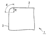
ここで、本発明の表面被覆切削工具は、図1に示すように、基材1の上に、被覆膜が形成されるものであり、工具表面において、すくい面2、逃げ面3、および刃先稜線部4を含むものである。
Here, as shown in FIG. 1, the surface-coated cutting tool of the present invention is such that a coating film is formed on a substrate 1, and on the tool surface, a
<被膜>
本発明の表面被覆切削工具の上記基材上に形成される被膜は、少なくとも後述の第1被膜と第2被膜と第3被膜とを含むものである。該第1被膜は、上記基材と後述の第2被膜との間に位置するようにして形成される。また、第3被膜は、第1被膜と第2被膜との間に位置するようにして形成される。
<Coating>
The film formed on the substrate of the surface-coated cutting tool of the present invention includes at least a first film, a second film, and a third film, which will be described later. The first film is formed so as to be positioned between the base material and a second film described later. The third coating is formed so as to be positioned between the first coating and the second coating.
また、このような被膜は、これらの第1被膜〜第2被膜以外に、第4被膜や他の被膜を含むことができる。第4被膜は、上記第2被膜上に形成される。 Moreover, such a film can contain a 4th film and another film other than these 1st film-2nd film. The fourth film is formed on the second film.
なお、このような被膜の合計厚みは、1μm以上30μm以下とすることが好ましく、より好ましくはその上限が25μm以下、さらに好ましくは20μm以下、その下限が2μm以上、さらに好ましくは3μm以上である。その厚みが1μm未満の場合、耐摩耗性や耐酸化性等の特性が十分に示されない場合があり、30μmを超えると耐欠損性が低下するため好ましくない。以下、これらの被膜についてさらに詳細に説明する。 In addition, it is preferable that the total thickness of such a film shall be 1 micrometer or more and 30 micrometers or less, More preferably, the upper limit is 25 micrometers or less, More preferably, it is 20 micrometers or less, The minimum is 2 micrometers or more, More preferably, it is 3 micrometers or more. When the thickness is less than 1 μm, characteristics such as wear resistance and oxidation resistance may not be sufficiently exhibited, and when it exceeds 30 μm, the chipping resistance decreases, which is not preferable. Hereinafter, these coating films will be described in more detail.
<第1被膜>
本発明の第1被膜は、化学蒸着法(CVD法)により単層または多層として形成され、基材と第2被膜との間に位置するものであって、α型酸化アルミニウム(α−Al2O3)を少なくとも一層含むによって構成されるものであり、かつ後述するセラミックを用いた機械的衝撃を与える衝撃によって付与された圧縮残留応力を有するものである。本明細書において、α型酸化アルミニウムをα型アルミナという場合もある。
<First coating>
The first coating of the present invention is formed as a single layer or a multilayer by a chemical vapor deposition method (CVD method), and is positioned between the substrate and the second coating, and is formed of α-type aluminum oxide (α-Al 2 It comprises at least one layer of O 3 ) and has a compressive residual stress imparted by an impact that gives a mechanical impact using a ceramic described later. In the present specification, α-type aluminum oxide is sometimes referred to as α-type alumina.
このような第1被膜は、高温時の耐酸化性に優れるとともに、高硬度を有する上、αアルミナをCVDで成膜する際には800℃以上の高温が必要であり、基材との間で強い密着力を有するため極めて優れた耐摩耗性を有するものである。しかも、κ型アルミナよりも粒界強度に優れるα型アルミナをCVD法により成膜しているので、α型アルミナの優れた粒界強度を活かしてα型アルミナ中への亀裂の導入を抑制し、さらにα型アルミナ中に後述の機械的衝撃処理により大きな圧縮応力が導入されているため優れた靭性を有し、特に、α型アルミナが残留圧縮応力を有するので耐欠損性が飛躍的に向上される。また、圧縮応力を導入する際、後述のとおりセラミック粒子を用いた機械的衝撃を施しているので、被膜表面を平滑にすることができるものであり、CVD法により成膜した表面が金属等によって汚染され、第3被膜との密着力に悪影響を与えることを防止している。 Such a first coating is excellent in oxidation resistance at high temperatures, has high hardness, and requires a high temperature of 800 ° C. or higher when depositing α-alumina by CVD. It has very good wear resistance because of its strong adhesion. In addition, α-type alumina, which has better grain boundary strength than κ-type alumina, is formed by the CVD method, so the introduction of cracks in α-type alumina is suppressed by utilizing the superior grain boundary strength of α-type alumina. Furthermore, it has excellent toughness because large compressive stress is introduced into the α-type alumina by the mechanical impact treatment described later. Especially, since the α-type alumina has residual compressive stress, the fracture resistance is dramatically improved. Is done. In addition, when compressive stress is introduced, since the mechanical impact using ceramic particles is applied as described later, the coating surface can be smoothed, and the surface formed by the CVD method is made of metal or the like. It is prevented from being contaminated and adversely affecting the adhesion with the third coating.
なお、α型アルミナへの亀裂の導入が少ないことは、機械的衝撃処理がかかりにくい部位(穴付きチップの場合は穴の中)でのα型アルミナ膜中およびその下層のCVD膜中に存在する亀裂本数と、機械的衝撃処理が施された部位においてα型アルミナ膜中およびその下層のCVD膜中に存在する亀裂本数を比較することによって確認できる。 Note that the introduction of cracks into α-type alumina is low in the α-type alumina film at the site where mechanical shock treatment is difficult (in the case of a holed chip, in the hole) and in the underlying CVD film. This can be confirmed by comparing the number of cracks to be generated and the number of cracks present in the α-type alumina film and the CVD film below it at the site subjected to the mechanical shock treatment.
本発明は、このように最外層ではなく内層となる第1被膜として、α型酸化アルミニウムからなる被膜を化学蒸着法により形成し、かつセラミックを用いた機械的衝撃を与える処理を行うことを特徴の1つとしている。これにより、該被膜が単にCVD法により形成される場合と比べて、α型アルミナ中に引っ張り応力の解放ではなく、圧縮応力を導入することができ、かつ、第3被膜との密着性を向上させることができる。さらに、靭性の向上に資する被膜の上にこのα型酸化アルミニウム被膜を形成するといった従来例のような構成ではないため、靭性の向上に資する被膜の圧縮応力がアニールされて靭性が低下するという問題を解消することができる。 The present invention is characterized in that a coating made of α-type aluminum oxide is formed by a chemical vapor deposition method as the first coating that is not the outermost layer but the inner layer, and a mechanical shock treatment using ceramic is performed. One of them. As a result, as compared with the case where the coating is simply formed by the CVD method, it is possible to introduce a compressive stress in the α-type alumina instead of releasing the tensile stress, and to improve the adhesion with the third coating. Can be made. Furthermore, since the α-type aluminum oxide coating is not formed on the coating that contributes to the improvement of toughness, the compressive stress of the coating that contributes to the improvement of toughness is annealed and the toughness decreases. Can be eliminated.
なお、このような圧縮残留応力を有するα型酸化アルミニウム層は工具の全面である必要はなく、切刃として作用するにげ面、すくい面および刃先稜線部の少なくとも一部に存在すれば効果が期待できる。 Note that the α-type aluminum oxide layer having such compressive residual stress does not need to be the entire surface of the tool, and it is effective if it exists on at least a part of the ridge surface, the rake surface, and the edge of the cutting edge that acts as a cutting edge. I can expect.
このような第1被膜を形成する化学蒸着法としては、従来公知の化学蒸着法であればいずれのものも採用することができ、たとえば、HT−CVD法、MT−CVD法、MO−CVD法等を挙げることができる。これらの中でも、特にHT−CVD法、MT−CVD法を採用することが好ましい。 As the chemical vapor deposition method for forming such a first film, any conventionally known chemical vapor deposition method can be employed. For example, HT-CVD method, MT-CVD method, MO-CVD method can be adopted. Etc. Among these, it is particularly preferable to employ the HT-CVD method and the MT-CVD method.
また、上記圧縮残留応力とは「−」(マイナス)の数値(単位:本発明では「GPa」を使う)で表される応力をいう。なお、数値を使わずに圧縮残留応力の大小を表現する場合は、上記数値の絶対値が大きくなる程、圧縮残留応力が大きいと表現し、また上記数値の絶対値が小さくなる程、圧縮残留応力が小さいと表現するものとする。一般に、圧縮残留応力が大きくなる程高い靭性を示す。また、引張残留応力とは、「+」(プラス)の数値(単位:本発明では「GPa」を使う)で表される応力をいう。 The compressive residual stress is a stress represented by a numerical value “−” (minus) (unit: “GPa” is used in the present invention). In addition, when expressing the magnitude of compressive residual stress without using numerical values, it expresses that the compressive residual stress increases as the absolute value of the numerical value increases, and the compressive residual stress decreases as the absolute value of the numerical value decreases. It shall be expressed that the stress is small. Generally, the higher the compressive residual stress, the higher the toughness. Further, the tensile residual stress refers to a stress represented by a numerical value “+” (plus) (unit: “GPa” is used in the present invention).
なお、このような残留応力は、X線応力測定装置を用いたsin2ψ法により測定することができ、工具のすくい面または逃げ面の平坦部に位置する任意の点3点(これらの各点は当該部位の応力を代表できるように互いに0.5mm以上の距離を離して選択することが好ましい)以上の応力を該sin2ψ法により測定し、その平均値を求めることにより測定することができる。 Such residual stress can be measured by the sin 2 ψ method using an X-ray stress measuring device, and can be measured at any three points (each of these points located on the rake face or flank flat portion of the tool). (The point is preferably selected at a distance of 0.5 mm or more from each other so that the stress of the part can be represented.) The above stress is measured by the sin 2 ψ method, and the average value is obtained. Can do.
このようなX線を用いたsin2ψ法は、多結晶材料の残留応力の測定方法として広く用いられているものであり、たとえば「X線応力測定法」(日本材料学会、1981年株式会社養賢堂発行)の54〜66頁に詳細に説明されている方法を用いれば良い。 The sin 2 ψ method using X-rays is widely used as a method for measuring the residual stress of a polycrystalline material. For example, “X-ray stress measurement method” (Japan Society of Materials Science, 1981 Corporation) The method described in detail on pages 54 to 66 of Yokendo) may be used.
このような第1被膜の残留応力、特にα型アルミナの残留応力は、上記の通り、−6GPa以上−0.1GPa以下、さらに好ましくはその上限が−0.2GPa以下、さらに好ましくは−0.3GPa以下、その下限が−5GPa以上、さらに好ましくは−4GPa以上の範囲の応力とすることが好適である。−0.1GPaを超える残留応力を有する場合には、靭性が劣る(耐欠損性が劣る)ことになる。一方、残留応力が−6GPa未満になると大きな圧縮応力を有することから被膜の自己破壊を生じる場合がある。 As described above, the residual stress of the first coating, particularly the residual stress of α-type alumina, is −6 GPa or more and −0.1 GPa or less, more preferably the upper limit is −0.2 GPa or less, and further preferably −0. It is preferable that the stress is 3 GPa or less and the lower limit is −5 GPa or more, more preferably −4 GPa or more. When the residual stress exceeds −0.1 GPa, the toughness is inferior (breakage resistance is inferior). On the other hand, if the residual stress is less than −6 GPa, the film may have a large compressive stress, which may cause self-destruction of the coating.
また、このような第1被膜は、α型酸化アルミニウムによって構成されるものであるが、このα型酸化アルミニウムと、ZrまたはHfの少なくともいずれかの酸化物との複合酸化物によって構成されるものとすることもできる。ZrまたはHfを含有することにより、酸化アルミニウムの微細化による高硬度化や断熱性の向上という特性を付与することができる。 Further, such a first coating is composed of α-type aluminum oxide, and is composed of a composite oxide of this α-type aluminum oxide and at least one of Zr and Hf oxides. It can also be. By containing Zr or Hf, it is possible to impart properties such as higher hardness and improved heat insulation by miniaturization of aluminum oxide.
なお、本発明のα型酸化アルミニウム層には、ZrおよびHf以外の金属(たとえば、B、Si、Ti、Cr、Y、Ybなど)を20原子%以下含有する場合も含む。 Note that the α-type aluminum oxide layer of the present invention includes a case in which a metal other than Zr and Hf (for example, B, Si, Ti, Cr, Y, Yb, etc.) is contained in an amount of 20 atomic% or less.
ここで、α型酸化アルミニウムと、ZrまたはHfの少なくともいずれかの酸化物との複合酸化物とは、ZrまたはHfの少なくともいずれか一方または両方が上記α型酸化アルミニウムの結晶格子の正規の位置に置換型として入る場合、該結晶格子間に侵入型として入る場合、金属間化合物を形成する場合、非晶質として存在する場合等、いずれの場合の酸化物も含むものである。 Here, the composite oxide of α-type aluminum oxide and at least one of Zr and Hf is a normal position of the crystal lattice of α-type aluminum oxide in which at least one or both of Zr and Hf is In this case, oxides in any case are included, for example, when they enter as a substitution type, when they enter as an interstitial type between the crystal lattices, when an intermetallic compound is formed, or when they exist as amorphous.
このような第1被膜は、0.5μm以上25μm以下の厚み(多層で形成される場合はその全体の厚み)を有することが好ましく、より好ましくはその上限が20μm以下、さらに好ましくは15μm以下、その下限が1μm以上、さらに好ましくは2μm以上である。その厚みが0.5μm未満の場合、十分な圧縮応力が付与できなくなるとともに十分な耐摩耗性を示さなくなる場合があり、25μmを超えると耐欠損性が低下するため好ましくない。 Such a first coating preferably has a thickness of 0.5 μm or more and 25 μm or less (when formed in a multilayer, the total thickness thereof), more preferably the upper limit thereof is 20 μm or less, more preferably 15 μm or less, The lower limit is 1 μm or more, more preferably 2 μm or more. If the thickness is less than 0.5 μm, sufficient compressive stress cannot be applied and sufficient wear resistance may not be exhibited. If it exceeds 25 μm, the chipping resistance decreases, which is not preferable.
<第2被膜>
本発明の第2被膜は、物理蒸着法(PVD法)により単層または多層として形成され、周期律表のIVa族元素(Ti、Zr、Hf等)、Va族元素(V、Nb、Ta等)、VIa族元素(Cr、Mo、W等)、Al、およびSiからなる群から選ばれる少なくとも1種の元素と、炭素、窒素、酸素、および硼素からなる群から選ばれる少なくとも1種の元素とからなる化合物(ただしα型酸化アルミニウムは除く)の少なくとも一層によって構成されるものであり、かつ圧縮残留応力を有するものである。このような第2被膜は、高硬度で耐摩耗性に優れるとともに、極めて優れた靭性を示すものである。なお、このように物理蒸着法により形成された第2被膜は、圧縮残留応力を有し、膜厚方向に導入された亀裂を有さない被膜となる。
<Second coating>
The second coating of the present invention is formed as a single layer or a multilayer by physical vapor deposition (PVD method), and includes a group IVa element (Ti, Zr, Hf, etc.) and a group Va element (V, Nb, Ta, etc.) in the periodic table. ), Group VIa elements (Cr, Mo, W, etc.), Al, and Si, and at least one element selected from the group consisting of carbon, nitrogen, oxygen, and boron And a compound having a compressive residual stress (excluding α-type aluminum oxide). Such a second coating has high hardness and excellent wear resistance, and exhibits extremely excellent toughness. In addition, the 2nd film formed by physical vapor deposition in this way becomes a film which has a compression residual stress and does not have a crack introduced in the film thickness direction.
このような第2被膜を物理蒸着法により形成するのは、第一に被膜に圧縮残留応力を付与するためである。このような物理蒸着法は、従来公知の物理蒸着法であればいずれのものも採用することができ、たとえばイオンプレーティング法、スパッタリング法等を挙げることができる。これらの中でも、特にカソードアークイオンプレーティング法、バランスドまたはアンバランスドマグネトロンスパッタリング法、または、これらを組み合わせた方法を採用することが好ましい。また、このような第2被膜は、上記の第1被膜上に形成されるものであって、特に第1被膜の直上に形成されていることが好ましい。 The reason why such a second film is formed by physical vapor deposition is to first apply compressive residual stress to the film. As such a physical vapor deposition method, any conventionally known physical vapor deposition method can be adopted, and examples thereof include an ion plating method and a sputtering method. Among these, it is particularly preferable to employ a cathode arc ion plating method, a balanced or unbalanced magnetron sputtering method, or a method combining these. Moreover, such a 2nd film is formed on said 1st film, Comprising: It is preferable to be formed especially just on a 1st film.
そして、この第2被膜は、周期律表のIVa族元素、Va族元素、VIa族元素、Al、およびSiからなる群から選ばれる少なくとも1種の元素と、炭素、窒素、酸素、および硼素からなる群から選ばれる少なくとも1種の元素とからなる化合物によって構成される。このような化合物としては、たとえば、TiAlN、TiAlSiN、TiAlCrSiN、AlCrN、AlCrSiN、TiZrN、TiAlMoN、TiAlNbN、TiSiN、AlCrTaV、AlTiVN、TiB2TiGrHfN、CrSiWN、TiAlCN、TiSiCN、AlZrON、AlCrCN、AlHfN、CrSiBON、TiAlWN、AlCrMoCN、TiAlBN、TiAlCrSiBCNO等を挙げることができる。また、この第2被膜はこれらの化合物を5nm以上5μmの厚みで積層する場合を含む。 The second film comprises at least one element selected from the group consisting of group IVa elements, group Va elements, group VIa elements, Al and Si in the periodic table, and carbon, nitrogen, oxygen, and boron. It is comprised by the compound which consists of at least 1 sort (s) of element chosen from the group which consists of. Examples of such compounds include TiAlN, TiAlSiN, TiAlCrSiN, AlCrN, AlCrSiN, TiZrN, TiAlMoN, TiAlNbN, TiSiN, AlCrTaV, AlTiVN, TiB 2 TiGrHfN, CrSiWN, TiAlCN, TiSiCN, AlZrON, AlCrN, AlZrON, AlCrN, AlCrMoCN, TiAlBN, TiAlCrSiBCNO, and the like. In addition, the second coating includes a case where these compounds are laminated with a thickness of 5 nm or more and 5 μm.
また、この第2被膜のうち少なくとも一層は、より好ましくはSiを含むことが好適である。このような化合物としては、たとえば、TiAlSiN、AlCrSiN、TiAlCrSiN、TiSiN、CrSiBON、TiAlSiBN、AlCrSiCN等を挙げることができる。 In addition, at least one layer of the second coating preferably contains Si. Examples of such compounds include TiAlSiN, AlCrSiN, TiAlCrSiN, TiSiN, CrSiBON, TiAlSiBN, and AlCrSiCN.
このように該化合物の構成元素としてSiを含むことにより、第3被膜に対する密着性がさらに向上したとともに、高温時の耐酸化性も飛躍的に向上したものとなる。このように高温時の耐酸化性の向上は、高速切削時に必要とされ、特に本発明のようにα型酸化アルミニウム、γ型酸化アルミニウムまたは非晶質酸化アルミニウムからなる第3被膜の上に形成される場合において有用となる。なぜなら、このような第3被膜は、低熱伝導性の被膜であることから、第2被膜に発生した熱は基材側に放熱され難く、以って第2被膜の温度上昇が顕著となり高温時の耐酸化性が特に要求されるからである。 Thus, by including Si as a constituent element of the compound, the adhesion to the third coating is further improved, and the oxidation resistance at high temperature is also greatly improved. Thus, the improvement in oxidation resistance at high temperatures is required at the time of high-speed cutting, and in particular, it is formed on the third film made of α-type aluminum oxide, γ-type aluminum oxide or amorphous aluminum oxide as in the present invention. This is useful when Because such a third coating is a low thermal conductivity coating, the heat generated in the second coating is difficult to dissipate to the base material side, so that the temperature rise of the second coating becomes remarkable and at high temperatures. This is because the oxidation resistance is particularly required.
さらに本発明の第2被膜は、圧縮残留応力を有することから、高い靭性を示すものとなる。ここで、残留応力とは、上記の第1被膜について既に説明した通りの内部応力であって、好ましくは−10GPa以上−1GPa以下、さらに好ましくはその上限が−1.5GPa以下、さらに好ましくは−2GPa以下、その下限が−8GPa以上、さらに好ましくは−7GPa以上の範囲の応力とすることが好適である。−1GPaを超える残留応力を有する場合には、靭性が劣る(耐欠損性が劣る)ことになり、一方、残留応力が−10GPa未満になると圧縮応力が大きくなり過ぎて被膜の自己破壊による剥離を生じる場合がある。なお、このような圧縮残留応力は、第1被膜で説明したsin2ψ法を用いた同様の方法により測定することができる。また、第2被膜が多層で形成される場合には、最大の圧縮応力(その絶対値が最大となる圧縮応力)を有する層の応力を第2被膜の圧縮残留応力とするものとする。 Furthermore, since the 2nd film of this invention has a compressive residual stress, it will show high toughness. Here, the residual stress is an internal stress as already described with respect to the first coating, and is preferably −10 GPa or more and −1 GPa or less, more preferably the upper limit is −1.5 GPa or less, more preferably − It is suitable that the stress is 2 GPa or less and the lower limit is −8 GPa or more, more preferably −7 GPa or more. When the residual stress exceeds -1 GPa, the toughness is inferior (breakage resistance is poor). On the other hand, when the residual stress is less than -10 GPa, the compressive stress becomes too large and the coating is peeled off due to self-destruction. May occur. Such compressive residual stress can be measured by the same method using the sin 2 ψ method described in the first film. When the second coating is formed of multiple layers, the stress of the layer having the maximum compressive stress (the compressive stress having the maximum absolute value) is set as the compressive residual stress of the second coating.
このような第2被膜は、0.3μm以上10μm以下の厚み(多層で形成される場合はその全体の厚み)を有することが好ましく、より好ましくはその上限が7μm以下、さらに好ましくは5μm以下、その下限が0.5μm以上、さらに好ましくは1μm以上である。その厚みが0.3μm未満の場合、十分な耐摩耗性が示されなくなるとともに十分な靭性を示さなくなる場合があり、10μmを超えると耐欠損性が低下するため好ましくない。 Such a second coating preferably has a thickness of 0.3 μm or more and 10 μm or less (when formed in a multilayer, the total thickness thereof), more preferably the upper limit thereof is 7 μm or less, more preferably 5 μm or less, The lower limit is 0.5 μm or more, more preferably 1 μm or more. If the thickness is less than 0.3 μm, sufficient wear resistance may not be exhibited and sufficient toughness may not be exhibited. If the thickness exceeds 10 μm, the fracture resistance decreases, which is not preferable.
<第3被膜>
本発明の第3被膜は、単層または多層であって、上記第1被膜と上記第2被膜との間に位置し、物理的蒸着法により形成されるものであって、第1被膜と第2被膜の両者に対して優れた密着力を有することにより、被膜の層間剥離を防止する作用を示すものである。当該物理的蒸着法としては、第2被膜において説明したものと同様のものを用いることができる。
<Third coating>
The third coating of the present invention is a single layer or a multilayer, is located between the first coating and the second coating, and is formed by a physical vapor deposition method. By having excellent adhesion to both of the two coatings, it exhibits the action of preventing delamination of the coatings. As the physical vapor deposition method, the same method as described in the second coating can be used.
当該第3被膜は、セラミック粒子を用いた機械的衝撃処理を施された第1被膜の上に形成されているので、第1被膜との密着性に優れ、耐剥離性が向上する。当該機械的衝撃処理では、従来の鋼球などを用いたブラスト処理に伴う鉄粉の付着等が発生しないため、メディアによって被膜表面が汚染されることがなく、平滑な被膜表面を有するためである。さらに、第1被膜と同一の組成(酸化型アルミナ)を有するので、第1被膜との密着性はさらに向上し、耐剥離性がますます良好となる。 Since the third coating is formed on the first coating that has been subjected to the mechanical shock treatment using ceramic particles, the third coating is excellent in adhesion to the first coating and the peel resistance is improved. This is because the mechanical impact treatment does not cause adhesion of iron powder associated with blasting using a conventional steel ball or the like, and thus the coating surface is not contaminated by the media and has a smooth coating surface. . Furthermore, since it has the same composition (oxidized alumina) as the first coating, the adhesion with the first coating is further improved, and the peel resistance is further improved.
このような第3被膜は、上記第1被膜と上記第2被膜との間に位置するものであって、α型酸化アルミニウム、γ型酸化アルミニウムまたは非晶質酸化アルミニウムによって構成される。特に、第1被膜直上に形成されることが好ましい。また、第3被膜が多層の場合は、結晶系の異なる酸化アルミニウムが交互に積層される場合や、連続して積層されている場合、また、ランダムに積層されている場合を含む。α型、γ型または非晶質酸化アルミニウムのいずれかが単層で形成されていてもよい。 Such a third coating is located between the first coating and the second coating, and is composed of α-type aluminum oxide, γ-type aluminum oxide, or amorphous aluminum oxide. In particular, it is preferably formed immediately above the first film. In addition, the case where the third coating is a multilayer includes the case where aluminum oxides having different crystal systems are alternately laminated, the case where they are continuously laminated, and the case where they are laminated randomly. Either α-type, γ-type, or amorphous aluminum oxide may be formed as a single layer.
また、第3被膜は、物理的蒸着法により形成されているので、残留圧縮応力を有するものであり、結果として高い靭性および高い耐欠損性を示すものとなる。ここで、圧縮残留応力とは、上記の第1被膜について既に説明した通りの内部応力であるが、α型酸化アルミニウムを形成した場合は、被覆温度が700〜800℃と高温になるため、圧縮残留応力は1GPa以下の小さい値となりやすく、γ型や非晶質酸化アルミニウムは、X線の回折ピークが明瞭に現われにくく、sin2ψ法では残留応力を定量化することは難しい。ただし、膜断面を鏡面研磨し、被膜の膜厚方向に亀裂が導入されていないことが確認できれば、被膜中には圧縮残留応力または小さな引張残留応力が導入されていると考えることができる。 Moreover, since the 3rd film is formed by the physical vapor deposition method, it has a residual compressive stress and, as a result, shows a high toughness and a high fracture resistance. Here, the compressive residual stress is the internal stress as already described for the first coating, but when α-type aluminum oxide is formed, the coating temperature is as high as 700 to 800 ° C. Residual stress tends to be a small value of 1 GPa or less, and γ-type and amorphous aluminum oxide do not easily show an X-ray diffraction peak, and it is difficult to quantify the residual stress by the sin 2 ψ method. However, if the cross section of the film is mirror-polished and it is confirmed that no crack is introduced in the film thickness direction of the film, it can be considered that compressive residual stress or small tensile residual stress is introduced into the film.
このような第3被膜は、0.01μm以上3μm以下の厚み(多層で形成される場合はその全体の厚み)を有することが好ましく、より好ましくはその上限が2.5μm以下、さらに好ましくは2μm以下、その下限が0.03μm以上、さらに好ましくは0.05μm以上である。その厚みが0.01μm未満の場合、上記密着性を向上させる効果が十分に示されない場合があり、3μmを超えても効果に大差なく経済的に不利となる。 Such a third coating preferably has a thickness of 0.01 μm or more and 3 μm or less (when it is formed of multiple layers, its total thickness), more preferably its upper limit is 2.5 μm or less, and even more preferably 2 μm. Hereinafter, the lower limit is 0.03 μm or more, and more preferably 0.05 μm or more. If the thickness is less than 0.01 μm, the effect of improving the adhesion may not be sufficiently exhibited, and if it exceeds 3 μm, the effect is economically disadvantageous with no significant difference.
また、このような第3被膜は、α型酸化アルミニウム、γ型酸化アルミニウムまたは非晶質酸化アルミニウムによって構成されるものであるが、このα型酸化アルミニウム、γ型酸化アルミニウムまたは非晶質酸化アルミニウムと、ZrまたはHfの少なくともいずれかの酸化物との複合酸化物によって構成されるものとすることもできる。ZrまたはHfを含有することにより、酸化アルミニウムの微細化による高硬度化や断熱性の向上が期待できる。 Such a third coating is composed of α-type aluminum oxide, γ-type aluminum oxide, or amorphous aluminum oxide, and this α-type aluminum oxide, γ-type aluminum oxide, or amorphous aluminum oxide. And a composite oxide of at least one of Zr and Hf oxides. Inclusion of Zr or Hf can be expected to increase the hardness and improve the heat insulating property by making aluminum oxide finer.
ここで、α型酸化アルミニウム、γ型酸化アルミニウムまたは非晶質酸化アルミニウムと、ZrまたはHfの少なくともいずれかの酸化物との複合酸化物とは、ZrまたはHfの少なくともいずれか一方または両方が上記α型酸化アルミニウムまたはγ型酸化アルミニウムの結晶格子の正規の位置に置換型として入る場合、該結晶格子間に侵入型として入る場合、金属間化合物を形成する場合、非晶質として存在する場合等、いずれの場合の酸化物も含むものである。 Here, the composite oxide of α-type aluminum oxide, γ-type aluminum oxide, or amorphous aluminum oxide and at least one of Zr and Hf is an oxide of at least one of Zr and Hf, or both When entering a normal position of the crystal lattice of α-type aluminum oxide or γ-type aluminum oxide as a substitution type, entering as an interstitial type between the crystal lattices, forming an intermetallic compound, existing as an amorphous state, etc. In any case, the oxide is included.
ここで、上記第1被膜の圧縮残留応力をσ1、第2被膜の圧縮残留応力をσ2とする場合、σ1<σ2の関係を有するように規定することが特に好ましく、このσ1<σ2という関係の下、第1被膜において−6GPa以上−0.1GPa以下の残留応力を有し、第2被膜において−10GPa以上−1GPa以下の残留応力を有し、第3被膜が圧縮残留応力を有するかまたは膜厚方向に亀裂を有さないことが特に好適である。このように規定することにより、特に第1被膜と第2被膜と第3被膜との密着性に優れたものとなる。 Here, when the compressive residual stress of the first coating film is σ1 and the compressive residual stress of the second coating film is σ2, it is particularly preferable that the relationship is σ1 <σ2, and the relationship of σ1 <σ2 is satisfied. The first film has a residual stress of −6 GPa or more and −0.1 GPa or less, the second film has a residual stress of −10 GPa or more and −1 GPa or less, and the third film has a compressive residual stress or a film It is particularly preferred that there is no crack in the thickness direction. By prescribing in this way, the adhesion between the first film, the second film, and the third film is particularly excellent.
<第4被膜>
本発明の第4被膜は、所望により、上記第2被膜上に形成されるものであって、仕上げ面粗さの向上、耐溶着性の向上、耐剥離性の向上、外観品質の向上、使用済コーナーの識別性の容易化、第2被膜に対する保護性の向上(たとえば、耐酸化性の向上等)などの作用を示すものである。
<4th coat>
The fourth coating of the present invention is formed on the second coating as desired, and is improved in finished surface roughness, improved welding resistance, improved peel resistance, improved appearance quality, and use. It shows effects such as easy identification of finished corners and improved protection against the second coating (for example, improved oxidation resistance).
このような第4被膜は、Ti、Cr、Si、V、Al、ZrおよびHfからなる群から選ばれる少なくとも1種の元素と、炭素、窒素、酸素、および硼素からなる群から選ばれる少なくとも1種の元素とからなる化合物によって単層または多層として構成される。 Such a fourth film is at least one element selected from the group consisting of Ti, Cr, Si, V, Al, Zr and Hf, and at least one selected from the group consisting of carbon, nitrogen, oxygen and boron. A single layer or a multilayer is constituted by a compound composed of a seed element.
このような第4被膜として好適な化合物としては、たとえばAlN、ZrN、CrN、AlZrN、AlON、AlHfN、AlCN、ZrCN、TiN、TiCN、TiSiCN、TiBN、Al2O3(γ型もしくはアモルファス)などを挙げることができる。 Examples of compounds suitable as the fourth coating include AlN, ZrN, CrN, AlZrN, AlON, AlHfN, AlCN, ZrCN, TiN, TiCN, TiSiCN, TiBN, and Al 2 O 3 (γ type or amorphous). Can be mentioned.
このような第4被膜は、0.1μm以上3μm以下の厚み(多層で形成される場合はその全体の厚み)を有することが好ましく、より好ましくはその上限が2μm以下、さらに好ましくは1.5μm以下、その下限が0.2μm以上、さらに好ましくは0.3μm以上である。その厚みが0.1μm未満の場合、仕上げ面粗さの向上、耐溶着性の向上、耐剥離性の向上、外観品質の向上、使用済コーナーの識別性の容易化、第2被膜に対する保護性の向上(たとえば、耐酸化性の向上等)などの作用効果が十分に示されない場合があり、3μmを超えても効果に大差なく経済的に不利となる。 Such a fourth coating preferably has a thickness of 0.1 μm or more and 3 μm or less (when it is formed of multiple layers, its total thickness), more preferably its upper limit is 2 μm or less, and even more preferably 1.5 μm. Hereinafter, the lower limit is 0.2 μm or more, and more preferably 0.3 μm or more. When the thickness is less than 0.1 μm, the finish surface roughness is improved, the welding resistance is improved, the peel resistance is improved, the appearance quality is improved, the used corners are easily distinguished, and the second film is protected. In some cases, the effect of improvement (for example, improvement in oxidation resistance) may not be sufficiently exhibited, and even if it exceeds 3 μm, there is no great difference in effect and it is economically disadvantageous.
このような第4被膜は、第2被膜および第3被膜と同様に物理蒸着法により形成することが好ましい。製造効率が向上する上、層間の密着力も向上するからである。 Such a fourth film is preferably formed by physical vapor deposition in the same manner as the second film and the third film. This is because the manufacturing efficiency is improved and the adhesion between the layers is also improved.
<製造方法>
本発明の表面被覆切削工具の製造方法は、上記第1被膜を化学蒸着法(CVD)で形成する第1ステップと、上記第3被膜を物理蒸着法により形成する第2ステップと、上記第2被膜を物理蒸着法により形成する第3ステップと、を含むことができる。ここで、第1ステップの後、第2ステップの前に、セラミックを用いた機械的衝撃処理により形成するステップを行うことを特徴とする。なお、化学蒸着法および物理蒸着法としては、上記で説明した方法が採用される。
<Manufacturing method>
The method for manufacturing a surface-coated cutting tool according to the present invention includes a first step of forming the first coating by chemical vapor deposition (CVD), a second step of forming the third coating by physical vapor deposition, and the second step. A third step of forming the film by physical vapor deposition. Here, after the first step, before the second step, a step of forming by mechanical impact treatment using ceramic is performed. In addition, the method demonstrated above is employ | adopted as a chemical vapor deposition method and a physical vapor deposition method.
なお、機械的衝撃処理とは、ノズルからの噴出や羽根車による投射などで運動エネルギーを与えられた粒子を対象物に打ち付ける処理やセラミックなどの硬質粒子を保持したブラシなどで対象物を叩く処理をいう。たとえば、ブラスト処理やピーニング処理、ブラシホーニング処理などを利用することができ、特に、ウェットブラストが好ましい。通常CVDで形成した被膜は引っ張り応力を有するものとなるが、当該処理により残留圧縮応力を導入することができる。特に、本発明においては、当該処理の際、メディアとしてセラミックを用いることに特徴を有する。セラミックを用いることにより、当該処理の際に被膜表面を汚染することがなく、当該被膜に接触する層との密着性に悪影響を及ぼすことがないためである。セラミック材料としては、Al2O3、SiC、ZrO2、TiC、SiO2、ガラスなどの材料を用いることができる。特に、球形のセラミック粒子が好ましい。ブラスト処理によるCVD膜の破壊を抑制しやすいためである。また、当該処理の条件としては、投射圧0.01〜0.5MPaの範囲内、投射距離0.5〜200mmの範囲内、微粉濃度5〜40vol%の範囲内、粒径10〜250μmの範囲内に設定することが好ましい。 The mechanical impact treatment is a treatment in which particles given kinetic energy, such as ejection from a nozzle or projection by an impeller, are hit against an object, or a target is hit with a brush holding hard particles such as ceramic. Say. For example, blasting, peening, brush honing, etc. can be used, and wet blasting is particularly preferable. Normally, a film formed by CVD has tensile stress, but residual compressive stress can be introduced by the treatment. In particular, the present invention is characterized in that ceramic is used as a medium in the treatment. This is because the use of ceramic does not contaminate the coating surface during the treatment and does not adversely affect the adhesion with the layer in contact with the coating. As the ceramic material, materials such as Al 2 O 3 , SiC, ZrO 2 , TiC, SiO 2 and glass can be used. In particular, spherical ceramic particles are preferred. This is because it is easy to suppress the destruction of the CVD film due to the blast treatment. Moreover, as the conditions of the said process, within the range of the projection pressure 0.01-0.5 MPa, the range of the projection distance 0.5-200 mm, the range of fine powder concentration 5-40 vol%, the range of particle size 10-250 micrometers It is preferable to set within.
中でも、湿式ブラストとすることで、ブラスト時にCVD膜表面に発生する高熱を冷却することが可能となり、CVD膜に導入された圧縮残留応力が熱でアニールされることなく、大きな圧縮残留応力を導入することが可能となる。 Above all, wet blasting makes it possible to cool the high heat generated on the surface of the CVD film during blasting and introduces large compressive residual stress without annealing the compressive residual stress introduced into the CVD film. It becomes possible to do.
また、本発明の表面被覆切削工具の製造方法は、上記のように第1被膜、第2被膜および第3被膜以外に、第4被膜が形成される場合には、当該第4被膜も物理蒸着法により形成することが好ましい。 In addition, when the fourth coating is formed in addition to the first coating, the second coating, and the third coating as described above, the method for manufacturing the surface-coated cutting tool according to the present invention also performs physical vapor deposition on the fourth coating. It is preferable to form by a method.
このように本発明の表面被覆切削工具の被膜においては、第1被膜については化学蒸着法(CVD)とセラミックを用いた機械的衝撃処理とを、そして、第2被膜および第3被膜、必要な場合には第4被膜について物理蒸着法により形成することが好ましい。これにより、各層間の優れた密着力と高い製造効率を得ることができるからである。 Thus, in the coating of the surface-coated cutting tool of the present invention, the first coating is subjected to chemical vapor deposition (CVD) and mechanical impact treatment using ceramic, and the second and third coatings are necessary. In some cases, the fourth coating is preferably formed by physical vapor deposition. This is because it is possible to obtain excellent adhesion between the layers and high production efficiency.
以下、実施例を挙げて本発明をより詳細に説明するが、本発明はこれらに限定されるものではない。なお、以下の各被膜の化学組成はXPS(X線光電子分光分析装置)によって確認し、圧縮残留応力は上記に説明したsin2ψ法により平均値を求めることによって算出した。また、以下では被膜を物理蒸着法であるカソードアークイオンプレーティング法により形成しているが、例えばバランスドまたはアンバランスドスパッタリング法や公知の他の物理蒸着法によっても成膜することは可能である。 EXAMPLES Hereinafter, although an Example is given and this invention is demonstrated in detail, this invention is not limited to these. The chemical composition of each film below was confirmed by XPS (X-ray photoelectron spectrometer), and the compressive residual stress was calculated by obtaining an average value by the sin 2 ψ method described above. In the following, the film is formed by the cathodic arc ion plating method which is a physical vapor deposition method, but it can also be formed by, for example, a balanced or unbalanced sputtering method or other known physical vapor deposition methods. is there.
<表面被覆切削工具の作製>
まず、基材として、グレードがJIS規格K20のWC基超硬合金であって、切削チップとしての形状がJIS規格CNMG120408であるものを使用し、これに公知のCVD製法を用いて約900℃でTiN、TiCNおよび約1000℃でα型酸化アルミナ材料よりなる第1被膜を形成した。
<Production of surface-coated cutting tool>
First, the base material is a WC standard cemented carbide of JIS standard K20 and the shape as a cutting tip is JIS standard CNMG120408, and this is performed at a temperature of about 900 ° C. using a known CVD method. A first coating made of TiN, TiCN and an α-type alumina material at about 1000 ° C. was formed.
次いで、CVDにより形成した第1被膜に、投射圧0.05〜0.3MPa、投射距離5〜100mm、セラミック濃度10〜30vol%の条件下、粒径150μm以下のAl2O3などのセラミック砥粒による機械的衝撃処理を施すことにより、残留圧縮応力を導入した。 Next, a ceramic abrasive such as Al 2 O 3 having a particle size of 150 μm or less is applied to the first coating formed by CVD under conditions of a projection pressure of 0.05 to 0.3 MPa, a projection distance of 5 to 100 mm, and a ceramic concentration of 10 to 30 vol%. Residual compressive stress was introduced by applying mechanical impact treatment with the grains.
第1被膜形成後の基板を、カソードアークイオンプレーティング装置に装着した。続いて、真空ポンプにより該装置のチャンバー内を1×10⁻³Pa以下に減圧するとともに、該装置内に設置されたヒーターにより上記基材の温度を500℃に加熱し、1時間保持した。 The substrate after the first coating was formed was attached to a cathode arc ion plating apparatus. Subsequently, the inside of the chamber of the apparatus was depressurized to 1 × 10 −3 Pa or less with a vacuum pump, and the temperature of the substrate was heated to 500 ° C. with a heater installed in the apparatus, and held for 1 hour.
次に、アルゴンガスを導入してチャンバー内の圧力を3.0Paに保持し、基板バイアス電源の電圧を徐々に上げながら−500Vとし、被膜の表面のクリーニングを15分間行なった。その後、アルゴンガスを排気した。 Next, argon gas was introduced to maintain the pressure in the chamber at 3.0 Pa, the voltage of the substrate bias power supply was gradually increased to −500 V, and the coating surface was cleaned for 15 minutes. Thereafter, argon gas was exhausted.
次いで、上記第1被膜表面に形成される被膜として、化学組成および積層構成が以下の表1に示したものとなるように金属蒸発源であるターゲットをセットするとともに、反応ガスとして窒素、メタン(炭素源として)、酸素または一酸化炭素(酸素源として)のいずれか1以上のガスを導入させながら、基材(基板)温度650℃、反応ガス圧2.0Pa、基板バイアス電圧を−200Vに維持したまま、カソード電極に100Aのアーク電流を供給し、アーク式蒸発源から金属イオンを発生させることにより、上記基材表面に各構成の被膜を形成した。 Next, as a film formed on the surface of the first film, a target which is a metal evaporation source is set so that the chemical composition and the laminated structure are as shown in Table 1 below, and nitrogen, methane ( While introducing at least one of oxygen or carbon monoxide (as an oxygen source), a base material (substrate) temperature of 650 ° C., a reaction gas pressure of 2.0 Pa, and a substrate bias voltage of −200 V While being maintained, an arc current of 100 A was supplied to the cathode electrode, and metal ions were generated from an arc evaporation source, thereby forming a coating film of each component on the surface of the substrate.
このようにして、表1に示したNo.1〜19の表面被覆切削工具を作製した。No.1〜15が本発明の実施例であり、No.16〜19は比較例である(ただし、各比較例の下記被膜については以下の成膜方法を採用した)。 Thus, No. 1 shown in Table 1 was obtained. 1-19 surface-coated cutting tools were produced. No. 1 to 15 are examples of the present invention. Reference numerals 16 to 19 are comparative examples (however, the following film forming method was adopted for the following films of each comparative example).
No.16の比較例は、第1被膜、第2被膜とともにCVD法(被膜温度900〜1000℃)により形成されており、0.4GPaの引張残留応力を有している。No.17および19の比較例は第1被膜がCVD法(1000℃)により形成された後、鋼球を用いて乾式でショットブラストを行った結果、それぞれの第1被膜には残留応力が導入されておらず、またそれぞれの第2被膜はPVD法で形成され、各々−2.9GPa、−3.0GPaの残留応力を有している。No.18の比較例は第1被膜がCVD法(被膜温度1000℃)で形成され、0.5GPaの残留応力を有し、続いて第2被膜がPVD法で形成されており、−2.8GPaの残留応力を有している。 No. The 16 comparative examples are formed by the CVD method (film temperature 900 to 1000 ° C.) together with the first film and the second film, and have a tensile residual stress of 0.4 GPa. No. In Comparative Examples 17 and 19, after the first film was formed by the CVD method (1000 ° C.), the result of dry blasting using a steel ball was that residual stress was introduced into each first film. In addition, each of the second coatings is formed by the PVD method and has residual stresses of -2.9 GPa and -3.0 GPa, respectively. No. In 18 comparative examples, the first film is formed by the CVD method (film temperature 1000 ° C.) and has a residual stress of 0.5 GPa, and then the second film is formed by the PVD method. Has residual stress.

上記表1において、被膜の積層構成は、左のものから順に基材上に積層させたことを示している。また、上記表1において、「※」の記号を付したものが比較例である。 In the said Table 1, the laminated structure of the film has shown having laminated | stacked on the base material in order from the left thing. Further, in Table 1 above, those given the symbol “*” are comparative examples.
そして、これらの表面被覆切削工具について、下記の条件により、耐摩耗性試験と断続切削試験を行なった。その結果を表1にあわせて示す。耐摩耗性試験では、逃げ面摩耗量が0.2mmとなる時間を測定し、その時間が長いもの程耐摩耗性に優れていることを示している。また、断続切削試験では、工具が欠損するまでの時間を測定し、その時間が多いもの程靭性に優れていることを示している。 These surface-coated cutting tools were subjected to an abrasion resistance test and an intermittent cutting test under the following conditions. The results are also shown in Table 1. In the wear resistance test, the time for the flank wear amount to be 0.2 mm was measured, and the longer the time, the better the wear resistance. In the intermittent cutting test, the time until the tool is broken is measured, and the longer the time is, the better the toughness is.
<耐摩耗性試験>
被削材:SCM435丸棒
切削速度:300m/min
切込みd:1.5mm
送りf:0.30mm/rev.
乾式/湿式:湿式
<断続切削試験>
被削材:SCM440(4本溝入り丸棒)
切削速度:200m/min
切込み:1.5mm
送り:0.4mm/rev.
乾式/湿式:乾式
上記表1において、「※」の記号を付したものが比較例である。また、「第1被膜残留応力」および「第2および第3被膜残留応力」の欄は、上記のsin2ψ法によりすくい面の平坦部の圧縮残留応力を測定した結果を示している。
<Abrasion resistance test>
Work material: SCM435 round bar Cutting speed: 300m / min
Cutting depth d: 1.5 mm
Feed f: 0.30 mm / rev.
Dry / Wet: Wet <Intermittent cutting test>
Work Material: SCM440 (Round bar with 4 grooves)
Cutting speed: 200 m / min
Cutting depth: 1.5mm
Feed: 0.4 mm / rev.
Dry type / wet type: Dry type In Table 1 above, the ones marked with “*” are comparative examples. Further, the columns of “first coating residual stress” and “second and third coating residual stress” show the results of measuring the compressive residual stress of the flat portion of the rake face by the sin 2 ψ method.
なお、第2被膜が被覆層からなるものについては、No.1、4、5、6、8、12、17、18、19については「TiAlN」、No.2、10については「TiAlSiN」、No.14については「AlCrSiN」、No.16については「TiCN」の残留応力を示している。 In addition, about what a 2nd film consists of a coating layer, it is No .. Nos. 1, 4, 5, 6, 8, 12, 17, 18, and 19 are “TiAlN”, No. 2 and 10, “TiAlSiN”, No. 14 for “AlCrSiN”, No. 14 16 represents the residual stress of “TiCN”.
以上、上記の表1から明らかなように、No.1〜No.15の本発明の実施例の表面被覆切削工具は、いずれも優れた耐摩耗性と靭性とを有するとともに、被膜の層間剥離を生じなかった。また、No.1〜No.15の本発明の実施例の表面被覆切削工具は、上記の耐摩耗性試験の条件を考慮すると高温時の耐酸化性や被膜の耐欠損性に優れていることが明らかであり、特に第2被膜中にSiを有するものにおいてその傾向が顕著である。これに対して、No.16およびNo.18の比較例の表面被覆切削工具は、第1被膜に引張残留応力を有するため、耐欠損性に劣る。No.17、19の比較例の表面被覆切削工具は、第1被膜に引張残留応力は有さないものの、鋼球を用いたブラスト処理のため、第2被膜の密着力が低く、耐摩耗性に劣る。 As can be seen from Table 1 above, no. 1-No. All of the 15 surface-coated cutting tools of the present invention had excellent wear resistance and toughness and did not cause delamination of the coating. No. 1-No. It is clear that the surface-coated cutting tool of the 15 examples of the present invention is excellent in oxidation resistance at high temperature and chipping resistance of the coating film in consideration of the above-mentioned conditions of the abrasion resistance test. This tendency is remarkable in those having Si in the coating. In contrast, no. 16 and no. Since the surface-coated cutting tool of 18 comparative examples has a tensile residual stress in the first coating, it is inferior in fracture resistance. No. Although the surface-coated cutting tools of Comparative Examples 17 and 19 do not have a tensile residual stress in the first coating, the second coating has low adhesion and poor wear resistance due to blasting using a steel ball. .
なお、本実施例では、基材として超硬合金製のものを用いたが、サーメット等他の素材のものを用いても同様の効果を得ることができる。また、基材としてチップブレーカを有するものを用いたが、チップブレーカを有していないものや、切削工具の上下面全面が研磨されたような工具(チップ)でも本実施例と同様の効果を得ることができる。 In the present embodiment, a cemented carbide material is used as the base material, but the same effect can be obtained even if a material such as cermet is used. In addition, although a material having a chip breaker was used as a base material, the same effect as in this example was obtained even for a tool without a chip breaker or a tool (chip) in which the entire upper and lower surfaces of the cutting tool were polished. Obtainable.
以上のように本発明の実施の形態および実施例について説明を行なったが、上述の各実施の形態および実施例の構成を適宜組み合わせることも当初から予定している。 Although the embodiments and examples of the present invention have been described as described above, it is also planned from the beginning to appropriately combine the configurations of the above-described embodiments and examples.
今回開示された実施の形態および実施例はすべての点で例示であって制限的なものではないと考えられるべきである。本発明の範囲は上記した説明ではなくて特許請求の範囲によって示され、特許請求の範囲と均等の意味および範囲内でのすべての変更が含まれることが意図される。 It should be understood that the embodiments and examples disclosed herein are illustrative and non-restrictive in every respect. The scope of the present invention is defined by the terms of the claims, rather than the description above, and is intended to include any modifications within the scope and meaning equivalent to the terms of the claims.
1 基材、2 すくい面、3 逃げ面、4 刃先稜線部。 1 base material, 2 rake face, 3 flank face, 4 edge edge line part.
Claims (11)
前記被膜は、化学蒸着法により形成される第1被膜と物理蒸着法により形成される第2被膜および第3被膜とを含み、
前記第1被膜は、前記基材と前記第2被膜との間に位置するものであって、α型酸化アルミニウムを少なくとも一層含むものであり、かつセラミック粒子を用いて機械的衝撃を与える処理によって付与された圧縮残留応力を有し、
前記第2被膜は、周期律表のIVa族元素、Va族元素、VIa族元素、Al、およびSiからなる群から選ばれる少なくとも1種の元素と、炭素、窒素、酸素、および硼素からなる群から選ばれる少なくとも1種の元素とからなる化合物よりなる少なくとも一層によって構成されるものであり、かつ圧縮残留応力を有し、
前記第3被膜は、前記第1被膜と前記第2被膜との間に位置するものであって、α型酸化アルミニウム、γ型酸化アルミニウムまたは非晶質酸化アルミニウムによって構成されるものであることを特徴とする表面被覆切削工具。 A surface-coated cutting tool comprising a substrate and a coating formed on the substrate,
The coating includes a first coating formed by chemical vapor deposition and a second coating and a third coating formed by physical vapor deposition,
The first coating is located between the base material and the second coating, includes at least one layer of α-type aluminum oxide, and has a mechanical impact using ceramic particles. With applied compressive residual stress,
The second coating is a group consisting of at least one element selected from the group consisting of group IVa elements, group Va elements, group VIa elements, Al, and Si in the periodic table, and carbon, nitrogen, oxygen, and boron. Is composed of at least one layer composed of a compound consisting of at least one element selected from: and has a compressive residual stress,
The third coating is located between the first coating and the second coating, and is composed of α-type aluminum oxide, γ-type aluminum oxide, or amorphous aluminum oxide. A surface-coated cutting tool.
前記第4被膜は、前記第2被膜上に形成され、かつTi、Cr、Si、V、Al、ZrおよびHfからなる群から選ばれる少なくとも1種の元素と、炭素、窒素、酸素および硼素からなる群から選ばれる少なくとも1種の元素とからなる化合物によって構成されることを特徴とする請求項1〜7のいずれかに記載の表面被覆切削工具。 The coating further includes a fourth coating,
The fourth film is formed on the second film and includes at least one element selected from the group consisting of Ti, Cr, Si, V, Al, Zr, and Hf, and carbon, nitrogen, oxygen, and boron. The surface-coated cutting tool according to any one of claims 1 to 7, wherein the surface-coated cutting tool is composed of a compound composed of at least one element selected from the group consisting of:
前記第1被膜を化学蒸着法により形成する第1ステップと、
前記第3被膜を物理蒸着法により形成する第2ステップと、
前記第2被膜を物理蒸着法により形成する第3ステップと、
を含み、
前記第1ステップにより形成された前記第1被膜に、前記第2ステップの前に、セラミック粒子を用いて機械的衝撃を与える処理を行うことを特徴とする表面被覆切削工具の製造方法。 It is a manufacturing method of the surface covering cutting tool in any one of Claims 1-9,
A first step of forming the first film by chemical vapor deposition;
A second step of forming the third coating by physical vapor deposition;
A third step of forming the second film by physical vapor deposition;
Including
A method for producing a surface-coated cutting tool, wherein the first coating formed in the first step is subjected to a process of applying a mechanical impact using ceramic particles before the second step.
Priority Applications (1)
| Application Number | Priority Date | Filing Date | Title |
|---|---|---|---|
| JP2005008085A JP2006192545A (en) | 2005-01-14 | 2005-01-14 | Surface-coated cutting tool and manufacturing method thereof |
Applications Claiming Priority (1)
| Application Number | Priority Date | Filing Date | Title |
|---|---|---|---|
| JP2005008085A JP2006192545A (en) | 2005-01-14 | 2005-01-14 | Surface-coated cutting tool and manufacturing method thereof |
Publications (1)
| Publication Number | Publication Date |
|---|---|
| JP2006192545A true JP2006192545A (en) | 2006-07-27 |
Family
ID=36798997
Family Applications (1)
| Application Number | Title | Priority Date | Filing Date |
|---|---|---|---|
| JP2005008085A Withdrawn JP2006192545A (en) | 2005-01-14 | 2005-01-14 | Surface-coated cutting tool and manufacturing method thereof |
Country Status (1)
| Country | Link |
|---|---|
| JP (1) | JP2006192545A (en) |
Cited By (13)
| Publication number | Priority date | Publication date | Assignee | Title |
|---|---|---|---|---|
| JP2007283478A (en) * | 2006-03-24 | 2007-11-01 | Sumitomo Electric Ind Ltd | Surface coated cutting tool |
| WO2008041402A1 (en) * | 2006-10-02 | 2008-04-10 | Sumitomo Electric Industries, Ltd. | Surface coating cutting tool |
| JP2008168365A (en) * | 2007-01-09 | 2008-07-24 | Sumitomo Electric Ind Ltd | Surface coated cutting tool |
| JP2008168364A (en) * | 2007-01-09 | 2008-07-24 | Sumitomo Electric Ind Ltd | Surface coated cutting tool |
| JP2008290163A (en) * | 2007-05-22 | 2008-12-04 | Sumitomo Electric Ind Ltd | Coating, cutting tool, and manufacturing method of coating |
| JP2009034781A (en) * | 2007-08-02 | 2009-02-19 | Sumitomo Electric Hardmetal Corp | Surface-coated cutting tool |
| JP2010512251A (en) * | 2006-09-15 | 2010-04-22 | サンドビック インテレクチュアル プロパティー アクティエボラーグ | Coated cutting tool |
| JP2010089221A (en) * | 2008-10-09 | 2010-04-22 | Mitsubishi Materials Corp | Surface-coated cutting tool |
| JP2010526680A (en) * | 2007-05-16 | 2010-08-05 | エーリコン・トレイディング・アーゲー・トリューバッハ | Cutting tools |
| EP2177295A4 (en) * | 2007-08-10 | 2012-01-11 | Mitsubishi Materials Corp | Surface-coated cutting tool |
| JP2012507625A (en) * | 2008-10-30 | 2012-03-29 | サンドビック インテレクチュアル プロパティー アクティエボラーグ | Coated tools and methods for making them |
| CN116555725A (en) * | 2023-07-10 | 2023-08-08 | 赣州澳克泰工具技术有限公司 | A kind of CVD coating cutting tool and preparation method thereof |
| DE112009005368B4 (en) | 2009-11-12 | 2023-12-28 | Osg Corp. | HARD COATE AND HARD COATED TOOL |
-
2005
- 2005-01-14 JP JP2005008085A patent/JP2006192545A/en not_active Withdrawn
Cited By (19)
| Publication number | Priority date | Publication date | Assignee | Title |
|---|---|---|---|---|
| JP2007283478A (en) * | 2006-03-24 | 2007-11-01 | Sumitomo Electric Ind Ltd | Surface coated cutting tool |
| US8409733B2 (en) | 2006-09-15 | 2013-04-02 | Sandvik Intellectual Property Ab | Coated cutting tool |
| EP2074241B1 (en) * | 2006-09-15 | 2018-11-14 | Sandvik Intellectual Property AB | Coated cutting tool |
| JP2010512251A (en) * | 2006-09-15 | 2010-04-22 | サンドビック インテレクチュアル プロパティー アクティエボラーグ | Coated cutting tool |
| WO2008041402A1 (en) * | 2006-10-02 | 2008-04-10 | Sumitomo Electric Industries, Ltd. | Surface coating cutting tool |
| JP5172687B2 (en) * | 2006-10-02 | 2013-03-27 | 住友電気工業株式会社 | Surface coated cutting tool |
| US8071211B2 (en) | 2006-10-02 | 2011-12-06 | Sumitomo Electric Industries, Ltd. | Surface-coated cutting tool |
| JPWO2008041402A1 (en) * | 2006-10-02 | 2010-02-04 | 住友電気工業株式会社 | Surface coated cutting tool |
| JP2008168364A (en) * | 2007-01-09 | 2008-07-24 | Sumitomo Electric Ind Ltd | Surface coated cutting tool |
| JP2008168365A (en) * | 2007-01-09 | 2008-07-24 | Sumitomo Electric Ind Ltd | Surface coated cutting tool |
| JP2010526680A (en) * | 2007-05-16 | 2010-08-05 | エーリコン・トレイディング・アーゲー・トリューバッハ | Cutting tools |
| JP2008290163A (en) * | 2007-05-22 | 2008-12-04 | Sumitomo Electric Ind Ltd | Coating, cutting tool, and manufacturing method of coating |
| JP2009034781A (en) * | 2007-08-02 | 2009-02-19 | Sumitomo Electric Hardmetal Corp | Surface-coated cutting tool |
| EP2177295A4 (en) * | 2007-08-10 | 2012-01-11 | Mitsubishi Materials Corp | Surface-coated cutting tool |
| JP2010089221A (en) * | 2008-10-09 | 2010-04-22 | Mitsubishi Materials Corp | Surface-coated cutting tool |
| JP2012507625A (en) * | 2008-10-30 | 2012-03-29 | サンドビック インテレクチュアル プロパティー アクティエボラーグ | Coated tools and methods for making them |
| DE112009005368B4 (en) | 2009-11-12 | 2023-12-28 | Osg Corp. | HARD COATE AND HARD COATED TOOL |
| CN116555725A (en) * | 2023-07-10 | 2023-08-08 | 赣州澳克泰工具技术有限公司 | A kind of CVD coating cutting tool and preparation method thereof |
| CN116555725B (en) * | 2023-07-10 | 2023-09-12 | 赣州澳克泰工具技术有限公司 | CVD (chemical vapor deposition) coating cutting tool and preparation method thereof |
Similar Documents
| Publication | Publication Date | Title |
|---|---|---|
| JP5261018B2 (en) | Surface coated cutting tool | |
| JP5297388B2 (en) | Surface coated cutting tool | |
| CN100496824C (en) | Surface-coated cutting tool | |
| JP5662680B2 (en) | Surface coated cutting tool | |
| CN101090789B (en) | Surface Coated Cutting Tools | |
| JP2009095907A (en) | Blade edge replaceable cutting chip | |
| JP2018521862A (en) | Tool with multilayer arc PVD coating | |
| WO2006064724A1 (en) | Surface-covered cutting tool | |
| JP5640242B2 (en) | Surface coated cutting tool | |
| JP5074772B2 (en) | Surface coated cutting tool | |
| JP4398224B2 (en) | Wear resistant parts | |
| JP4405835B2 (en) | Surface coated cutting tool | |
| JP4753144B2 (en) | Surface coated cutting tool | |
| JP4398287B2 (en) | Surface coated cutting tool | |
| JP5668262B2 (en) | Surface coated cutting tool | |
| JP4921984B2 (en) | Surface coated cutting tool | |
| JP2006192543A (en) | Surface-coated cutting tool and manufacturing method thereof | |
| JP5417650B2 (en) | Surface coated cutting tool | |
| JP2006192531A (en) | Surface-coated cutting tool and manufacturing method thereof | |
| JP5070621B2 (en) | Surface coated cutting tool | |
| JP2005262355A (en) | Surface-coated cutting tool | |
| JP2007196364A (en) | Surface-coated cutting tool and manufacturing method thereof | |
| JP2006192544A (en) | Surface-coated cutting tool and manufacturing method thereof | |
| JP5640243B2 (en) | Surface coated cutting tool | |
| JP2013052478A (en) | Tool coated with hard film |
Legal Events
| Date | Code | Title | Description |
|---|---|---|---|
| A621 | Written request for application examination |
Free format text: JAPANESE INTERMEDIATE CODE: A621 Effective date: 20070719 |
|
| A761 | Written withdrawal of application |
Free format text: JAPANESE INTERMEDIATE CODE: A761 Effective date: 20100324 |