JP2006199111A - Pneumatic tire, and method for using pneumatic tire - Google Patents
Pneumatic tire, and method for using pneumatic tire Download PDFInfo
- Publication number
- JP2006199111A JP2006199111A JP2005011954A JP2005011954A JP2006199111A JP 2006199111 A JP2006199111 A JP 2006199111A JP 2005011954 A JP2005011954 A JP 2005011954A JP 2005011954 A JP2005011954 A JP 2005011954A JP 2006199111 A JP2006199111 A JP 2006199111A
- Authority
- JP
- Japan
- Prior art keywords
- tire
- carcass
- folded portion
- pneumatic tire
- bead core
- Prior art date
- Legal status (The legal status is an assumption and is not a legal conclusion. Google has not performed a legal analysis and makes no representation as to the accuracy of the status listed.)
- Pending
Links
- 238000000034 method Methods 0.000 title claims abstract description 12
- 239000011324 bead Substances 0.000 claims abstract description 46
- 230000006835 compression Effects 0.000 description 10
- 238000007906 compression Methods 0.000 description 10
- 238000005452 bending Methods 0.000 description 7
- 238000010276 construction Methods 0.000 description 3
- 230000007935 neutral effect Effects 0.000 description 3
- 230000009466 transformation Effects 0.000 description 3
- 238000010586 diagram Methods 0.000 description 2
- 230000000694 effects Effects 0.000 description 2
- 238000005516 engineering process Methods 0.000 description 2
- 238000000926 separation method Methods 0.000 description 2
- 241000270295 Serpentes Species 0.000 description 1
- 238000011156 evaluation Methods 0.000 description 1
- 239000002184 metal Substances 0.000 description 1
- 230000002093 peripheral effect Effects 0.000 description 1
- 238000004804 winding Methods 0.000 description 1
Images


Landscapes
- Tires In General (AREA)
Abstract
Description
本発明は、カーカスの折返し部のコード切れ性を改良する空気入りタイヤ及び空気入りタイヤの使用方法に関する。 The present invention relates to a pneumatic tire for improving the cord breakability of a folded portion of a carcass and a method for using the pneumatic tire.
従来、ビードの耐久性を向上させるために、カーカスプライ端のセパレーションを改良する技術がある。 Conventionally, there is a technique for improving the separation of the end of the carcass ply in order to improve the durability of the bead.
具体的には、カーカスの折返しプライに角度を付ける技術(例えば、特許文献1及び特許文献2参照。)や、折り返しプライをカーカス本体部に一旦接近させた上で離反する形状を有する技術(例えば、特許文献3参照。)が開示されている。
一方、超重荷重建設車両用タイヤなどにおいては、タイヤ撓みによる大きなビード倒れ込み変形が生じ、カーカスの折返し部のコードが切れる場合がある。このようなコード切れ性に対しては、上述した従来技術では対応することが困難であった。 On the other hand, in a heavy-duty construction vehicle tire or the like, there is a case where a large bead collapse deformation occurs due to the tire deflection, and the cord of the folded portion of the carcass may be cut. It has been difficult to cope with such code breakage with the above-described prior art.
即ち、特許文献1や特許文献2に開示された折れ曲がりカーカス技術を適用したタイヤでは、タイヤの縦バネ係数が低減する。その結果、荷重負荷時のタイヤ撓みによるビード倒れ込み変形が増加し、カーカスの折返し部への圧縮入力が増加する。このため、折返し部のコードの切れ故障が生じ易くなる。 That is, in a tire to which the bent carcass technology disclosed in Patent Document 1 and Patent Document 2 is applied, the longitudinal spring coefficient of the tire is reduced. As a result, the bead collapse deformation due to tire deflection during load application increases, and the compression input to the carcass turn-up portion increases. For this reason, the breakage of the cord at the folded portion is likely to occur.
又、特許文献3に開示された折り返しカーカスを反り返らせる技術を適用したタイヤでは、反り返し部の折り返しカーカスへの圧縮入力が増加する。このため、折返し部のコードの切れ故障が生じ易くなる。 Further, in a tire to which the technology for turning the folded carcass disclosed in Patent Document 3 is applied, the compression input to the folded carcass of the bent portion increases. For this reason, the breakage of the cord at the folded portion is likely to occur.
そこで、本発明は、上記の問題に鑑み、カーカスの折返し部のコード切れ性を改良する空気入りタイヤ及び空気入りタイヤの使用方法を提供することを目的とする。 Then, an object of this invention is to provide the usage method of the pneumatic tire which improves the cord breakability of the folding | turning part of a carcass, and a pneumatic tire in view of said problem.
上記課題を解決するために、本発明の第1の特徴は、1対のビード部にそれぞれ埋設したビードコア間でトロイド状に延び、ビードコアの周りでその周面に沿わせてタイヤ幅方向内側から外側に、又は外側から内側に向けて巻き上げた折返し部を有する、少なくとも1枚のカーカスプライからなるカーカスを備える、扁平率80%以下の空気入りタイヤであって、折返し部を構成するコードは、ラジアル方向に対して0°〜10°で配置され、折返し部の端からビードコアのリム側端までのタイヤ径方向距離をCEとし、フランジ高さをFHとした場合、2×FH<CE<6×FHであり、タイヤ巾方向断面において、カーカス本体部に対する垂直線上の当該カーカス本体部と折返し部との距離をtとし、折返し部を構成するコードの直径をaとした場合、ビードコアのリム側端からタイヤ径方向に2×FH〜4×FHの領域において、3×a<t<5×aを満たす空気入りタイヤであることを要旨とする。 In order to solve the above-mentioned problem, the first feature of the present invention is that it extends in a toroid shape between bead cores embedded in a pair of bead portions, and extends from the inner side in the tire width direction around the bead core along the peripheral surface thereof. A pneumatic tire having a flat rate of 80% or less, including a carcass made of at least one carcass ply having a folded portion wound up outward or from the outside to the inside, and the cord constituting the folded portion is 2 × FH <CE <6, where the tire radial direction distance from the end of the folded portion to the rim side end of the bead core is CE and the flange height is FH. XFH, and in the cross section in the tire width direction, the distance between the carcass main body portion and the folded portion on the vertical line to the carcass main body portion is t, and the diameter of the cord constituting the folded portion is a If you, in the region of 2 × FH~4 × FH from the rim side end of the bead core in the tire radial direction, is summarized in that a pneumatic tire which satisfies the 3 × a <t <5 × a.
第1の特徴に係る空気入りタイヤによると、従来の空気入りタイヤより、折返し部を曲げ変形の中立面(カーカス本体部)に近い範囲に配置するため、荷重負荷時の折返し部への圧縮入力を低減し、カーカスの折返し部のコード切れ性を改良することができる。 According to the pneumatic tire according to the first feature, the folded portion is arranged in a range closer to the neutral surface (carcass main body portion) of the bending deformation than the conventional pneumatic tire, so that the folded portion is compressed when a load is applied. It is possible to reduce the input and improve the cord breakability of the folded portion of the carcass.
本発明の第2の特徴は、1対のビード部にそれぞれ埋設したビードコア間でトロイド状に延び、ビードコアの周りでその周面に沿わせてタイヤ幅方向内側から外側に、又は外側から内側に向けて巻き上げた折返し部を有する、少なくとも1枚のカーカスプライからなるカーカスを備え、扁平率80%以下であり、折返し部を構成するコードは、ラジアル方向に対して0°〜10°で配置され、折返し部の端からビードコアのリム側端までのタイヤ径方向距離をCEとし、フランジ高さをFHとした場合、2×FH<CE<6×FHであり、タイヤ巾方向断面において、カーカス本体部に対する垂直線上の当該カーカス本体部と折返し部との距離をtとし、折返し部を構成するコードの直径をaとした場合、ビードコアのリム側端からタイヤ径方向に2×FH〜4×FHの領域において、3×a<t<5×aを満たす空気入りタイヤの使用方法であって、セクションハイトをSHとした場合、FH/SH<0.15を満たすリムに空気入りタイヤを組む空気入りタイヤの使用方法であることを要旨とする。 The second feature of the present invention is that it extends in a toroid between bead cores embedded in a pair of bead portions, and extends from the inner side to the outer side in the tire width direction around the bead core, or from the outer side to the inner side. The carcass made of at least one carcass ply having a turned-up portion that is rolled up toward the surface, has a flatness of 80% or less, and the cords that make up the turned-up portion are arranged at 0 ° to 10 ° with respect to the radial direction When the distance in the tire radial direction from the end of the turn-up portion to the rim side end of the bead core is CE and the flange height is FH, 2 × FH <CE <6 × FH. When the distance between the carcass main body portion and the folded portion on the vertical line with respect to the portion is t, and the diameter of the cord constituting the folded portion is a, the tire radial direction from the rim side end of the bead core In the region of 2 × FH to 4 × FH, a method of using a pneumatic tire satisfying 3 × a <t <5 × a, where FH / SH <0.15 is satisfied when the section height is SH. The gist is that it is a method of using a pneumatic tire in which a pneumatic tire is assembled on a rim.
第2の特徴に係る空気入りタイヤの使用方法によると、フランジハイトの低いリムに組むことにより、撓み変形の範囲が広がり、荷重負荷時の折返し部の蛇行範囲を小さくすることができる。 According to the method for using the pneumatic tire according to the second feature, by assembling the rim having a low flange height, the range of flexural deformation is widened, and the meandering range of the folded portion when a load is applied can be reduced.
本発明によれば、カーカスの折返し部のコード切れ性を改良する空気入りタイヤ及び空気入りタイヤの使用方法を提供することができる。 ADVANTAGE OF THE INVENTION According to this invention, the usage method of the pneumatic tire which improves the cord breakability of the folding | turning part of a carcass and a pneumatic tire can be provided.
次に、図面を参照して、本発明の実施の形態を説明する。以下の図面の記載において、同一又は類似の部分には、同一又は類似の符号を付している。ただし、図面は模式的なものであり、各寸法の比率等は現実のものとは異なることに留意すべきである。従って、具体的な寸法等は以下の説明を参酌して判断すべきものである。又、図面相互間においても互いの寸法の関係や比率が異なる部分が含まれていることは勿論である。 Next, embodiments of the present invention will be described with reference to the drawings. In the following description of the drawings, the same or similar parts are denoted by the same or similar reference numerals. However, it should be noted that the drawings are schematic and ratios of dimensions and the like are different from actual ones. Accordingly, specific dimensions and the like should be determined in consideration of the following description. Moreover, it is a matter of course that portions having different dimensional relationships and ratios are included between the drawings.
(空気入りタイヤの構造)
本発明の実施形態に係る空気入りタイヤは、図1に示すように、タイヤ赤道面CLに対して、一対のビード部1及び一対のサイドウォール部と、サイドウォール部相互間にわたりトロイド状に連なるトレッド部とを備える。尚、本実施形態に係る空気入りタイヤは、扁平率80%以下の超重荷重建設車両用扁平ラジアルタイヤである。即ち、リム径が57”以上で、荷重負荷能力60mton以上で、荷重係数(k-factor)が1.7以上のラジアルタイヤである。
(Pneumatic tire structure)
As shown in FIG. 1, the pneumatic tire according to the embodiment of the present invention is connected to the tire equatorial plane CL in a toroid shape between the pair of bead portions 1 and the pair of sidewall portions and the sidewall portions. A tread portion. The pneumatic tire according to the present embodiment is a flat radial tire for a super heavy load construction vehicle having a flat rate of 80% or less. That is, a radial tire having a rim diameter of 57 "or more, a load carrying capacity of 60 mton or more, and a load factor (k-factor) of 1.7 or more.
カーカス5a、5bは、1対のビード部1にそれぞれ埋設したビードコア6間でトロイド状に延び、ビードコアの周りでその周面に沿わせてタイヤ幅方向内側から外側に、巻き回して構成され、サイドウォール部及びトレッド部を補強するトロイド状ラジアルカーカスである。尚、カーカスは、外側から内側に向けて巻き回して構成されてもよい。
The
又、カーカス5a、5bは、カーカス本体部5aと、巻き上げた折返し部5bを有し、少なくとも1枚のカーカスプライからなる。折返し部5bを構成するコードは、ラジアル方向に対して0°〜10°で配置される。
The
図1に示すように、折返し部5bの端からビードコア6のリム側端までのタイヤ径方向距離をCEとし、フランジ高さをFHとした場合、2×FH<CE<6×FHである。又、タイヤ巾方向断面において、カーカス本体部5aに対する垂直線上の当該カーカス本体部5aと折返し部5bとの距離をtとし、折返し部5bを構成するコードの直径をaとした場合、ビードコア6のリム側端からタイヤ径方向に2×FH〜4×FHの領域において、3×a<t<5×aを満たす。
As shown in FIG. 1, when the tire radial direction distance from the end of the folded
また、本実施形態に係る空気入りタイヤは、セクションハイト(タイヤの断面高さ)をSHとした場合、FH/SH<0.15を満たすリムに組み込まれて使用される。 Further, the pneumatic tire according to the present embodiment is used by being incorporated in a rim that satisfies FH / SH <0.15, where SH is the section height (tire cross-sectional height).
(作用及び効果)
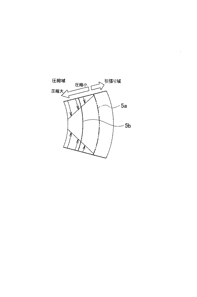
通常の空気入りタイヤに荷重を負荷した場合の、ビード部の変形について、図2を用いて説明する。
(Action and effect)
The deformation of the bead portion when a load is applied to a normal pneumatic tire will be described with reference to FIG.
まず、荷重を負荷しない場合は、図2の左図に示すように、カーカス本体部5a及び折返し部5bは、曲げ変形を受けない状態にある。
First, when no load is applied, the carcass
ここに荷重を負荷すると、ビード部は倒れ込みによる大きな曲げ変形を受ける。この曲げ変形における曲げの中立面は、カーカス本体部5aであり、カーカス本体部5aを中心として、タイヤ巾方向内側に引っ張り入力が、タイヤ巾方向外側に圧縮入力が作用する。図2の右図に示すように、折返し部5bには、圧縮入力が発生する。
When a load is applied here, the bead portion is subjected to a large bending deformation due to falling. The neutral plane of the bending in this bending deformation is the carcass
図3(a)に示すように、折返し部5bが圧縮入力を受けると、金属よりなるカーカスコードは収縮することができないため、折返し部5bが蛇行して圧縮を吸収する。その結果、図3(b)に示すように、折返し部5bは、タイヤ周方向面内で蛇行することとなる。このように、折返し部5bが大きく蛇行する結果、カーカスコード内のフィラメントに局部的な圧縮入力が発生し、フィラメントの切れに至る。
As shown in FIG. 3A, when the folded
上述した本実施形態に係る空気入りタイヤは、図4に示すように、従来の空気入りタイヤより、折返し部5bを曲げ変形の中立面(カーカス本体部5a)に近い範囲に配置する。このように、折返し部5bへの圧縮入力を低減することで、折返し部5bの蛇行を小さくして、フィラメントの切れを抑制することができる。
As shown in FIG. 4, the pneumatic tire according to the present embodiment described above arranges the folded
又、図2(b)において、無負荷時の折返し部5bのカーカス中心線をX、荷重負荷時の折り返し部5bのカーカス中心線をYとし、カーカスコード径をa、折返し部5bのカーカス中心線の蛇行量をbとする。この荷重負荷時とは、タイヤ回転軸に垂直方向に正規荷重対比80〜120%の荷重を負荷してタイヤを変形させた状態を指す。尚、ここで、「正規荷重」とは、米国のタイヤとリムの協会TRAが発行する2004年版のYEAR BOOKに定められた適用サイズ・プライレーティングにおける最大荷重を指す。図2(b)において、蛇行指数Z=b/aと定義すると、本実施形態に係る空気入りタイヤは、0<Z<0.5を満たすことができる。
In FIG. 2B, the carcass center line of the folded
又、本実施形態に係る空気入りタイヤにおいて、折返し部5bの端からビードコア6のリム側端までのタイヤ径方向距離をCEとし、フランジ高さをFHとした場合、2×FH<CE<6×FHである。2×FH<CEに設計することにより、大荷重入力時に、折り返し部5bがビードコアより引き抜けることによるバーストを防ぐことができ、CE<6×FHに設計することにより、カーカス本体部5aの動きの影響が少ない領域に、折り返し部5b端を配置し、折返し部5b端の歪を下げることができる。
In the pneumatic tire according to the present embodiment, when the distance in the tire radial direction from the end of the folded
又、本実施形態に係る空気入りタイヤにおいて、タイヤ巾方向断面において、カーカス本体部5aに対する垂直線上の当該カーカス本体部5aと折返し部5bとの距離をtとし、折返し部5bを構成するコードの直径をaとした場合、ビードコア6のリム側端からタイヤ径方向に2×FH〜4×FHの領域において、3×a<t<5×aを満たす。2×FH〜4×FHの領域は、折返し部5bのコードの圧縮変形が最大になることが分かった領域であり、tが3×aより小さいとプライ間の歪が大きくなるため、セパレーションが生じやすくなり、tが5×aより大きいと、折返し部5bが圧縮入力側に配置され、コード切れ性が改良されない。
Further, in the pneumatic tire according to the present embodiment, in the tire width direction cross section, the distance between the carcass
又、本実施形態に係る空気入りタイヤは、扁平率80%以下、リム径が57”以上、荷重負荷能力60mton以上、荷重係数(k-factor)が1.7以上の超重荷重建設車両用扁平ラジアルタイヤとして用いることが好ましい。このような超大型のタイヤでは、折返し部5bの圧縮歪が大きくなるため、本実施形態において説明した構造を採用することにより、コード切れ性を改良する利点が顕著である。
Further, the pneumatic tire according to the present embodiment is a flat for a super heavy load construction vehicle having a flatness ratio of 80% or less, a rim diameter of 57 "or more, a load load capacity of 60 mton or more, and a load factor (k-factor) of 1.7 or more. In such an ultra-large tire, the compression distortion of the folded-
又、本実施形態に係る空気入りタイヤは、セクションハイトをSHとした場合、FH/SH<0.15を満たすリムに組んで使用することができる。このように、フランジハイトの低いリムに組むことにより、撓み変形の範囲が広がり、荷重負荷時の折返し部の蛇行範囲を小さくすることができる。 Further, the pneumatic tire according to the present embodiment can be used by being assembled on a rim that satisfies FH / SH <0.15 when the section height is SH. As described above, by assembling the rim having a low flange height, the range of the bending deformation is widened, and the meandering range of the folded portion when a load is applied can be reduced.
次に、本発明を実施例により更に詳しく説明するが、本発明はこれらの例によってなんら限定されるものではない。 EXAMPLES Next, although an Example demonstrates this invention further in detail, this invention is not limited at all by these examples.
本発明の効果を確かめるため、実施例及び従来例に係る空気入りタイヤを試作した。尚、各供試タイヤのサイズは、59/80R63であり、リムサイズは44”×5”であった。実施例及び従来例に係る空気入りタイヤの構造は、表1に示すとおりである。
<ドラムライフ評価>
ドラムライフテストは、空気圧600kPa、荷重150%、ドラム回転速度8km/hでビート部故障(カーカスプライコードの破断)によって走行不能になるまでの距離を測定し、従来例のタイヤをコントロールとして指数化することにより評価した。数値が大きいほど耐久性が良好である。
<Drum life evaluation>
The drum life test measures the distance until it becomes impossible to run due to a failure of the beat section (carcass ply cord breakage) at an air pressure of 600 kPa, a load of 150%, and a drum rotation speed of 8 km / h, and is indexed using the conventional tire as a control. It was evaluated by doing. The larger the value, the better the durability.
(結果)
結果を表2に示す。
The results are shown in Table 2.
実施例は、従来例と比較すると、ビード部の耐久性に優れる、即ち、コード切れ性が改良されることが分かった。従って、タイヤ巾方向断面において、カーカス本体部に対する垂直線上の当該カーカス本体部と前記折返し部との距離をtとし、前記折返し部を構成するコードの直径をaとした場合、ビードコアのリム側端からタイヤ径方向に2×FH〜4×FHの領域において、3×a<t<5×aを満たし、蛇行指数Zを0<Z<0.5とすることにより、コード切れ性が改良されることが分かった。 It was found that the example is superior in the durability of the bead portion, that is, the cord breakability is improved as compared with the conventional example. Therefore, in the cross section in the tire width direction, when the distance between the carcass main body portion and the folded portion on the vertical line with respect to the carcass main body portion is t, and the diameter of the cord constituting the folded portion is a, the rim side end of the bead core In the region from 2 × FH to 4 × FH in the tire radial direction, the cord breakability is improved by satisfying 3 × a <t <5 × a and the meandering index Z being 0 <Z <0.5. I found out.
1…ビード部、5…カーカス、5a…カーカス本体部、5b…折返し部、6…ビードコア、10…フランジ DESCRIPTION OF SYMBOLS 1 ... Bead part, 5 ... Carcass, 5a ... Carcass main-body part, 5b ... Fold-up part, 6 ... Bead core, 10 ... Flange
Claims (2)
前記折返し部を構成するコードは、ラジアル方向に対して0°〜10°で配置され、
前記折返し部の端からビードコアのリム側端までのタイヤ径方向距離をCEとし、フランジ高さをFHとした場合、2×FH<CE<6×FHであり、
タイヤ巾方向断面において、カーカス本体部に対する垂直線上の当該カーカス本体部と前記折返し部との距離をtとし、前記折返し部を構成するコードの直径をaとした場合、ビードコアのリム側端からタイヤ径方向に2×FH〜4×FHの領域において、3×a<t<5×aを満たすことを特徴とする空気入りタイヤ。 A bead core extending in a toroid between the bead cores embedded in a pair of bead portions, and having a turn-up portion wound around the bead core from the inner side to the outer side in the tire width direction or from the outer side to the inner side along the circumferential surface. A pneumatic tire having a flat rate of 80% or less, comprising a carcass made of at least one carcass ply,
The cord constituting the folded portion is arranged at 0 ° to 10 ° with respect to the radial direction,
When the distance in the tire radial direction from the end of the folded portion to the rim side end of the bead core is CE and the flange height is FH, 2 × FH <CE <6 × FH,
In the cross section in the tire width direction, when the distance between the carcass main body portion on the vertical line to the carcass main body portion and the folded portion is t, and the diameter of the cord constituting the folded portion is a, the tire starts from the rim side end of the bead core. A pneumatic tire characterized by satisfying 3 × a <t <5 × a in a region of 2 × FH to 4 × FH in the radial direction.
扁平率80%以下であり、
前記折返し部を構成するコードは、ラジアル方向に対して0°〜10°で配置され、
前記折返し部の端からビードコアのリム側端までのタイヤ径方向距離をCEとし、フランジ高さをFHとした場合、2×FH<CE<6×FHであり、
タイヤ巾方向断面において、カーカス本体部に対する垂直線上の当該カーカス本体部と前記折返し部との距離をtとし、前記折返し部を構成するコードの直径をaとした場合、ビードコアのリム側端からタイヤ径方向に2×FH〜4×FHの領域において、3×a<t<5×aを満たす空気入りタイヤの使用方法であって、
セクションハイトをSHとした場合、FH/SH<0.15を満たすリムに前記空気入りタイヤを組むことを特徴とする空気入りタイヤの使用方法。
A bead core extending in a toroid between the bead cores embedded in a pair of bead portions, and having a folded portion wound around the bead core from the inner side to the outer side in the tire width direction or from the outer side to the inner side along the circumferential surface. A carcass made of at least one carcass ply,
Flatness is 80% or less,
The cord constituting the folded portion is arranged at 0 ° to 10 ° with respect to the radial direction,
When the distance in the tire radial direction from the end of the folded portion to the rim side end of the bead core is CE and the flange height is FH, 2 × FH <CE <6 × FH,
In the cross section in the tire width direction, when the distance between the carcass main body portion on the vertical line to the carcass main body portion and the folded portion is t, and the diameter of the cord constituting the folded portion is a, the tire starts from the rim side end of the bead core. In the region of 2 × FH to 4 × FH in the radial direction, a method of using a pneumatic tire satisfying 3 × a <t <5 × a,
When the section height is SH, the pneumatic tire is assembled on a rim that satisfies FH / SH <0.15.
Priority Applications (1)
| Application Number | Priority Date | Filing Date | Title |
|---|---|---|---|
| JP2005011954A JP2006199111A (en) | 2005-01-19 | 2005-01-19 | Pneumatic tire, and method for using pneumatic tire |
Applications Claiming Priority (1)
| Application Number | Priority Date | Filing Date | Title |
|---|---|---|---|
| JP2005011954A JP2006199111A (en) | 2005-01-19 | 2005-01-19 | Pneumatic tire, and method for using pneumatic tire |
Publications (1)
| Publication Number | Publication Date |
|---|---|
| JP2006199111A true JP2006199111A (en) | 2006-08-03 |
Family
ID=36957497
Family Applications (1)
| Application Number | Title | Priority Date | Filing Date |
|---|---|---|---|
| JP2005011954A Pending JP2006199111A (en) | 2005-01-19 | 2005-01-19 | Pneumatic tire, and method for using pneumatic tire |
Country Status (1)
| Country | Link |
|---|---|
| JP (1) | JP2006199111A (en) |
Cited By (1)
| Publication number | Priority date | Publication date | Assignee | Title |
|---|---|---|---|---|
| WO2008072425A1 (en) | 2006-12-08 | 2008-06-19 | Bridgestone Corporation | Heavy duty pneumatic radial tire |
Citations (7)
| Publication number | Priority date | Publication date | Assignee | Title |
|---|---|---|---|---|
| JPH04185510A (en) * | 1990-11-20 | 1992-07-02 | Bridgestone Corp | Pneumatic radial tire for construction vehicle |
| JP2000085320A (en) * | 1998-09-17 | 2000-03-28 | Sumitomo Rubber Ind Ltd | Heavy duty tire |
| JP2000168318A (en) * | 1998-12-10 | 2000-06-20 | Sumitomo Rubber Ind Ltd | Tubeless tire |
| JP2000198326A (en) * | 1998-10-29 | 2000-07-18 | Sumitomo Rubber Ind Ltd | Pneumatic tire |
| JP2001113920A (en) * | 1999-10-21 | 2001-04-24 | Sumitomo Rubber Ind Ltd | Pneumatic tire |
| JP2001150910A (en) * | 1999-11-29 | 2001-06-05 | Bridgestone Corp | Pneumatic tire |
| WO2002085647A1 (en) * | 2001-04-16 | 2002-10-31 | Sumitomo Rubber Industries, Ltd | Pneumatic tire |
-
2005
- 2005-01-19 JP JP2005011954A patent/JP2006199111A/en active Pending
Patent Citations (7)
| Publication number | Priority date | Publication date | Assignee | Title |
|---|---|---|---|---|
| JPH04185510A (en) * | 1990-11-20 | 1992-07-02 | Bridgestone Corp | Pneumatic radial tire for construction vehicle |
| JP2000085320A (en) * | 1998-09-17 | 2000-03-28 | Sumitomo Rubber Ind Ltd | Heavy duty tire |
| JP2000198326A (en) * | 1998-10-29 | 2000-07-18 | Sumitomo Rubber Ind Ltd | Pneumatic tire |
| JP2000168318A (en) * | 1998-12-10 | 2000-06-20 | Sumitomo Rubber Ind Ltd | Tubeless tire |
| JP2001113920A (en) * | 1999-10-21 | 2001-04-24 | Sumitomo Rubber Ind Ltd | Pneumatic tire |
| JP2001150910A (en) * | 1999-11-29 | 2001-06-05 | Bridgestone Corp | Pneumatic tire |
| WO2002085647A1 (en) * | 2001-04-16 | 2002-10-31 | Sumitomo Rubber Industries, Ltd | Pneumatic tire |
Cited By (2)
| Publication number | Priority date | Publication date | Assignee | Title |
|---|---|---|---|---|
| WO2008072425A1 (en) | 2006-12-08 | 2008-06-19 | Bridgestone Corporation | Heavy duty pneumatic radial tire |
| US8291952B2 (en) | 2006-12-08 | 2012-10-23 | Bridgestone Corporation | Pneumatic radial tire for heavy load |
Similar Documents
| Publication | Publication Date | Title |
|---|---|---|
| JP5390392B2 (en) | Pneumatic tire | |
| JP5216304B2 (en) | Pneumatic tires for construction vehicles | |
| JP5750156B2 (en) | Pneumatic tire | |
| US8863800B2 (en) | Pneumatic tire with specified carcass folded section and notched portion | |
| JP4482504B2 (en) | Pneumatic tire | |
| JP6342669B2 (en) | Pneumatic tire | |
| WO2008072425A1 (en) | Heavy duty pneumatic radial tire | |
| JP2010111370A (en) | Pneumatic tire | |
| JP2010274862A (en) | Pneumatic tire | |
| JP4471260B2 (en) | Pneumatic tires for motorcycles | |
| JP4741955B2 (en) | Pneumatic tire | |
| JP2006199111A (en) | Pneumatic tire, and method for using pneumatic tire | |
| JP5993402B2 (en) | Heavy duty tube tire | |
| JP4945136B2 (en) | Pneumatic tire | |
| JP2010260408A (en) | Pneumatic tire | |
| WO2014175347A1 (en) | Pneumatic radial tire | |
| JP2006218936A (en) | Pneumatic radial tire for heavy load | |
| JP4070454B2 (en) | Pneumatic tire | |
| JP2008222000A (en) | Pneumatic tire | |
| JPH07164838A (en) | Pneumatic radial tire for heavy load | |
| JP2003154819A (en) | Pneumatic tire | |
| JPH08192608A (en) | Bead structure for pneumatic tire | |
| JP2001191750A (en) | Pneumatic tire excellent in durability at bead portion | |
| JP2014231259A (en) | Pneumatic tire | |
| JP2015074306A (en) | Pneumatic tire |
Legal Events
| Date | Code | Title | Description |
|---|---|---|---|
| A621 | Written request for application examination |
Free format text: JAPANESE INTERMEDIATE CODE: A621 Effective date: 20080108 |
|
| A977 | Report on retrieval |
Free format text: JAPANESE INTERMEDIATE CODE: A971007 Effective date: 20100825 |
|
| A131 | Notification of reasons for refusal |
Free format text: JAPANESE INTERMEDIATE CODE: A131 Effective date: 20100907 |
|
| A02 | Decision of refusal |
Free format text: JAPANESE INTERMEDIATE CODE: A02 Effective date: 20110104 |