JP2006200417A - Fuel injection rail - Google Patents
Fuel injection rail Download PDFInfo
- Publication number
- JP2006200417A JP2006200417A JP2005012058A JP2005012058A JP2006200417A JP 2006200417 A JP2006200417 A JP 2006200417A JP 2005012058 A JP2005012058 A JP 2005012058A JP 2005012058 A JP2005012058 A JP 2005012058A JP 2006200417 A JP2006200417 A JP 2006200417A
- Authority
- JP
- Japan
- Prior art keywords
- upper case
- fuel injection
- injection rail
- injector mounting
- mounting member
- Prior art date
- Legal status (The legal status is an assumption and is not a legal conclusion. Google has not performed a legal analysis and makes no representation as to the accuracy of the status listed.)
- Pending
Links
Images


Classifications
-
- F—MECHANICAL ENGINEERING; LIGHTING; HEATING; WEAPONS; BLASTING
- F02—COMBUSTION ENGINES; HOT-GAS OR COMBUSTION-PRODUCT ENGINE PLANTS
- F02M—SUPPLYING COMBUSTION ENGINES IN GENERAL WITH COMBUSTIBLE MIXTURES OR CONSTITUENTS THEREOF
- F02M55/00—Fuel-injection apparatus characterised by their fuel conduits or their venting means; Arrangements of conduits between fuel tank and pump F02M37/00
- F02M55/02—Conduits between injection pumps and injectors, e.g. conduits between pump and common-rail or conduits between common-rail and injectors
- F02M55/025—Common rails
-
- F—MECHANICAL ENGINEERING; LIGHTING; HEATING; WEAPONS; BLASTING
- F02—COMBUSTION ENGINES; HOT-GAS OR COMBUSTION-PRODUCT ENGINE PLANTS
- F02M—SUPPLYING COMBUSTION ENGINES IN GENERAL WITH COMBUSTIBLE MIXTURES OR CONSTITUENTS THEREOF
- F02M55/00—Fuel-injection apparatus characterised by their fuel conduits or their venting means; Arrangements of conduits between fuel tank and pump F02M37/00
- F02M55/004—Joints; Sealings
Landscapes
- Engineering & Computer Science (AREA)
- Chemical & Material Sciences (AREA)
- Combustion & Propulsion (AREA)
- Mechanical Engineering (AREA)
- General Engineering & Computer Science (AREA)
- Fuel-Injection Apparatus (AREA)
Abstract
【課題】 本体の一部を樹脂製の部品で置き換えた構造したフューエルインジェクションレールにおいて、組み付けがワンタッチで容易にし、さらに、樹脂製部品の接合部のシール性の信頼性向上を図る。
【解決手段】 インジェクタ取付部材32の外周に凹部35を形成し、凹部35とは離れた位置にアッパケース30とインジェクタ取付部32との間をシールするシール部材29を配置し、アッパケース30の側面には、凹部35に係合する係合部37を形成するとともに、インジェクタ取付部材32のシール部材取付部寸法とアッパケース30の内寸法とがシール部材29のしめ代を決定する関係に設定する。
【選択図】 図2PROBLEM TO BE SOLVED: To facilitate assembly with one touch in a fuel injection rail having a structure in which a part of a main body is replaced with a resin part, and further improve the reliability of a sealing property of a joint part of a resin part.
A recess 35 is formed on the outer periphery of an injector mounting member 32, and a seal member 29 that seals between the upper case 30 and the injector mounting portion 32 is disposed at a position away from the recess 35. On the side surface, an engaging portion 37 that engages with the recess 35 is formed, and the seal member mounting portion dimension of the injector mounting member 32 and the inner dimension of the upper case 30 are set to have a relationship that determines the interference of the seal member 29. To do.
[Selection] Figure 2
Description
本発明は、自動車のエンジンにおいて燃料噴射装置供給部に用いられるフューエルインジェクションレールに関する。 The present invention relates to a fuel injection rail used for a fuel injection device supply section in an automobile engine.
自動車のエンジンに燃料を供給する燃料供給系では、ポンプから燃料供給管を通して燃料をフューエルインジェクションレールに送り、このフューエルインジェクションレールに取り付けられているインジェクタに燃料を分配して、各インジェクタからエンジンのインテークマニホールドに噴射している。 In a fuel supply system for supplying fuel to an automobile engine, fuel is sent from a pump to a fuel injection rail through a fuel supply pipe, and the fuel is distributed to injectors attached to the fuel injection rail. The manifold is sprayed.
この種のフューエルインジェクションレールは、金属製のものが主流であったが、近年では、樹脂製のものや、金属製部品と樹脂製部品との複合型のフューエルインジェクションレールが開発されている。そこで、図11、図12に、従来の複合型のフューエルインジェクションレールを示す(特許文献1)。 This type of fuel injection rail has been mainly made of metal, but in recent years, resin-made or composite fuel injection rails of metal parts and resin parts have been developed. FIG. 11 and FIG. 12 show a conventional composite fuel injection rail (Patent Document 1).
図11、図12において、フューエルインジェクションレール10の本体をなす主管1は、ソケット4がある壁面3が樹脂で成形されており、それ以外の側壁21、22および上面23は鋼板で作られている。壁面3は、その平面から直角方向下方にインジェクタを取り付けるためのソケット4が一体成形されている。主管1の側壁21、22の下端は外方に折り曲げられさらに内側へと折り返されることにより、内側に凹溝5が形成されており、この凹溝5に壁面3の外周縁が係合し、シール部材6を介してカシメにより固定されている。
11 and 12, in the main pipe 1 constituting the main body of the
このように金属製の主管1の一部を樹脂製の壁面3で置き換えることにより、ソケット相互の間隔や取り付け位置にばらつきがなくなり、また軽量化を達成することができるようになっている。
しかしながら、実公平5−43355号のように、樹脂製の部品である壁面3を主管1にカシメにより固定する構造において、十分なシール性を確保するためには、シール部材6全周に均一なカシメ代を持たせるために、主管1の側壁21、22を折り曲げて凹溝5を加工する際に厳密な管理のもとで曲げ加工を行わなければならない。しかし実際の量産過程では困難であり、信頼できるシール性能の量産品質を確保することは現実的ではない。
However, in the structure in which the
また、凹溝の加工、カシメ加工というように、難度の高い加工により製造工程が複雑化するという問題もある。 In addition, there is a problem that the manufacturing process becomes complicated due to processing with a high degree of difficulty, such as concave groove processing and caulking processing.
そこで、本発明の目的は、前記従来技術の有する問題点を解消し、本体の一部を樹脂製の部品で置き換えた構造のフューエルインジェクションレールでありながら、組み付けがワンタッチで容易である上に、樹脂製部品の接合部のシール性の信頼性向上を達成できるようにしたフューエルインジェクションレールを提供することにある。 Therefore, the object of the present invention is to solve the problems of the prior art, and while being a fuel injection rail having a structure in which a part of the main body is replaced with a resin part, assembly is easy with one touch. It is an object of the present invention to provide a fuel injection rail that can achieve an improvement in the reliability of the sealing performance of a joint part of resin parts.
前記の目的を達成するために、本発明は、燃料の導入される空間を形成する金属製のアッパケースと、インジェクタが取り付けられるソケット部を有する樹脂製のインジェクタ取付部材と、から本体を構成したフューエルインジェクションレールにおいて、前記インジェクタ取付部材の外周に凹部を形成し、前記凹部とは離れた位置に前記アッパケースとインジェクタ取付部との間をシールするシール部材を配置し、前記アッパケースの側面には、前記凹部に係合する係合部を形成するとともに、前記インジェクタ取付部材のシール部材取付部寸法と前記アッパケースの内寸法とが前記シール部材のしめ代を決定する関係に設定されていることを特徴とするものである。 In order to achieve the above-mentioned object, the present invention comprises a main body comprising a metal upper case forming a space into which fuel is introduced and a resin injector mounting member having a socket portion to which the injector is mounted. In the fuel injection rail, a recess is formed on the outer periphery of the injector mounting member, and a seal member for sealing between the upper case and the injector mounting portion is disposed at a position away from the recess, and is provided on a side surface of the upper case. Is formed so as to form an engaging portion that engages with the recess, and the seal member mounting portion dimension of the injector mounting member and the inner dimension of the upper case determine the interference of the seal member. It is characterized by this.
本発明によれば、組み付けがワンタッチで容易である上に、アッパケースの内寸法や、インジェクタ取付部材のシール部材取付部寸法を管理することは容易であるので、シール性について信頼性の高い量産品質を確保することができる。 According to the present invention, assembly is easy with one touch, and it is easy to manage the inner dimensions of the upper case and the dimensions of the seal member mounting portion of the injector mounting member. Quality can be ensured.
以下、本発明によるフューエルインジェクションレールの実施形態について、添付の図面を参照しながら説明する。
第1実施形態
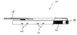
図1は、本発明の第1実施形態によるフューエルインジェクションレールの一部を切り欠いた側面図であり、図2は、フューエルインジェクションレールの本体の横断面を示す。
DESCRIPTION OF EMBODIMENTS Hereinafter, an embodiment of a fuel injection rail according to the present invention will be described with reference to the accompanying drawings.
First embodiment
FIG. 1 is a side view in which a part of a fuel injection rail according to the first embodiment of the present invention is cut away, and FIG. 2 shows a cross section of the main body of the fuel injection rail.
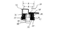
図1、図2において、参照番号20は、フューエルインジェクションレールの本体を示す。この本体20は、金属製のアッパケース30と、樹脂製のインジェクタ取付部材32とを組み合わせてなるものである。
1 and 2,
アッパケース30はステンレス鋼板を素材にプレス成形により細長い有底ケースの形状に絞り加工されたもので、燃料供給管28から燃料の導入される空間を形成する。インジェクタ取付部材32は、アッパケース30の開口を塞ぐ細長い板状に射出成形により成形された部材であり、図2に示すようにインジェクタ33が圧入により取り付けられる円筒状の穴がソケット部34として複数箇所に形成されている。
The
本実施形態では、アッパケース30に対してインジェクタ取付部材32を挿入するだけで以下のようにワンタッチで組み付けが完了する構造となっている。すなわち、インジェクタ取付部材32の外周には、周方向に延びる凹部35が形成されている。そして、凹部35に係合する係合部として、アッパケース30の長手方向の側面36には爪部37が形成されている。この爪部37は、長手方向にある程度の長さをもつ爪片を側面36から内側に折り曲げてなるものである。この場合、インジェクタ取付部材32をアッパーケース30に挿入する過程では、爪部37は外側に弾性変形してインジェクタ取付部材32の移動を許容するようになっている。
In the present embodiment, the assembly is completed by one touch as described below simply by inserting the
インジェクタ取付部材32の端面は、アッパケース30の上壁面30aに突き当たって凹溝35の位置を位置決めする突当部として構成されている。この突き合った状態では、爪部37は凹部35に係合する位置にある。
The end surface of the
インジェクタ取付部32の外周面には、凹部35から離れた位置にシール用溝38が形成されており、このシール用溝38には、アッパケース30とインジェクタ取付部材32との間を液密にシールするシール部材39が装着されている。
A
この実施形態では、インジェクタ取付部材32をアッパケース30に嵌合させるだけで信頼性の高いシール性が得られるように、インジェクタ取付部材32のシール部材取付部寸法とアッパケース30の内寸法とがシール部材32のしめ代を決定する関係に設定されている。例えば、図2において、アッパケース30の幅方向の内寸法をA、インジェクタ取付部材32にあってシール部材39の取付部寸法をB(この場合、シール用溝38のところの外径)とすると、内寸法Aとシール部材39の取付部寸法Bの差がどのように設定されるかで、シール部材39の効き方が違ってくる。したがって、内寸法Aに対してシール部材取付部寸法Bをシール部材39の適正なしめ代を見込んで設定すれば、シール部材39について信頼性の高いシール性を確保できる。この点は、長手方向の内寸法と取付部寸法の関係についても同様である。
In this embodiment, the dimension of the seal member mounting portion of the
以上のように構成される第1実施形態によれば、図3に示すように、インジェクタ取付部材32にシール部材39を装着しておき、インジェクタ取付部材32をアッパケース30に挿入する。そして、インジェクタ取付部材32の端面がアッパレース30の上壁面30aに突き当たるまで押し込む。
According to the first embodiment configured as described above, as shown in FIG. 3, the
これにより、図2に示すように、爪部37の先端がインジェクタ取付部材32の凹部35に係合するので、アッパケース30に対してインジェクタ取付部材32が固定される。このとき、シール部材39によるシールが効いているのは上述したとおりである。
Thereby, as shown in FIG. 2, the tip of the
このように、インジェクタ取付部材32をアッパケース30に嵌合させるだけでワンタッチで簡単に組み付けが完了する。しかも、量産する場合に、アッパケース30の内寸法や、インジェクタ取付部材32でのシール部材取付部寸法を管理することは容易であるので、シール性について信頼性の高い量産品質を確保することができる。
In this way, the assembly can be easily completed with one touch only by fitting the
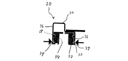
なお、図4に示すように、アッパケース30の爪部37については、最初から内側に折り曲げずに、インジェクタ取付部材32を先に嵌め込んでから外側が力を加えて折り曲げるようにしてもよい。
In addition, as shown in FIG. 4, about the nail |
第2実施形態
図5は、本発明の第2実施形態によるフューエルインジェクションレールを示す一部切り欠き側面図で、図6は横断面図である。
Second embodiment
FIG. 5 is a partially cutaway side view showing a fuel injection rail according to a second embodiment of the present invention, and FIG. 6 is a cross-sectional view.
この第2実施形態では、インジェクタ取付部材32を固定するのに、爪部37に代えて、アッパケース30の長手方向の側面から窪んで内側に突き出すように形成された複数の突起部40を利用している。この突起部40は、図6に示すように、要求される固定強度に応じて、適当な箇所に必要な数だけ形成される。
In the second embodiment, in order to fix the
インジェクタ取付部材32では、突起部40が係合する凹部35が形成されている点と、アッパケース30の内寸法に対してインジェクタ取付部材32でのシール部材取付部寸法をシール部材39の適正なしめ代を見込んで設定している点は第1実施形態と同様である。
In the
他方、この第2実施形態では、二つのシール部材39を用いて2段のシールを構成している。また、アッパケース30の断面形状に対応させて、凹部35の位置を位置決めする突き当て部として凸に盛り上がった第1突き当て部41と、板状の第2突き当て部42をインジェクタ取付部材32に一体形成している。
On the other hand, in the second embodiment, two
以上のように構成される第2実施形態によれば、第1実施形態と同様にインジェクタ取付部材32をアッパケース30に嵌合させるだけでワンタッチで簡単に組み付けが完了し、しかも、2段のシール部材39により、シール性について高い一層信頼性の高い量産品質を確保することができる。
According to the second embodiment configured as described above, as in the first embodiment, the assembly can be easily completed with one touch by simply fitting the
なお、シール部材39と凹部35の位置関係については、図6に示すように、シール部材39が凹部35の上側に位置してもよいし、図7に示すように、シール部材39が凹部の下側に位置してもよい。
Regarding the positional relationship between the
第3実施形態
次に、図8並びに図9は、本発明の第3実施形態によるフューエルインジェクションレールを示す。
Third Embodiment Next, FIGS. 8 and 9 show a fuel injection rail according to a third embodiment of the present invention.
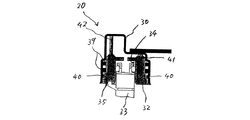
この第3実施形態は、第1実施形態のインジェクタ取付部材32に内圧変形防止部を設け、フューエルインジェクションレールに供給された燃料の内圧によりアッパケース30が変形したときのシール性能の低下を防止するように改良したものである。
図8に示すように、インジェクタ取付部材32の下端面には、外側に張り出すように内圧変形防止部44が全周に亘って一体的に形成されている。この内圧変形防止部44はコ字型に屈曲し、インジェクタ取付部材32を固定すると同時にアッパケース30の長手方向側面36の端縁部が嵌合可能になっている。
In this third embodiment, the
As shown in FIG. 8, an inner pressure
燃料による内圧が加わると、アッパケース30では長手方向の側面36はふくらむことがある。そして、側面36がふくらむとシール部材39のシール性能が著しく低下する。ところが、この第3実施形態によれば、アッパーケース30の長手方向側面36の端縁部が内圧変形防止部44に拘束されているので、ふくらむような変形を抑えられるので、シール性能の低下を確実に防止できる。このような内圧変形防止部は、インジェクタ取付部材32の全周に設ける必要はかならずしもなく、必要な部分に形成してもよい。また、別部品とすることも可能である。
When the internal pressure by the fuel is applied, the
なお、図9は、内圧変形防止部44を図4の実施形態のインジェクタ取付部材32に適用した例を示す。
FIG. 9 shows an example in which the internal pressure
第4実施形態
次に、図10は、本発明の第4実施形態によるフューエルインジェクションレールを示す。
この第4実施形態では、インジェクタ取付部材32を固定するのに、アッパケース30とは別部品の固定部材50を用いている。
Fourth embodiment
Next, FIG. 10 shows a fuel injection rail according to a fourth embodiment of the present invention.
In the fourth embodiment, a fixing
この固定部材50は、図1におけるソケット部34の穴を避けた位置で、必要な数が用いられる。固定部材50は、コ字型の部材で両側に爪部51が形成されている。アッパケース30の長手方向側面36には穴部52が形成されており、爪部51の先端は穴部52からアッパケース30の内側に突き出て、インジェクタ取付部材32の凹部35に係合するようになっている。なお、アッパケース30の内寸法に対してインジェクタ取付部材32でのシール部材取付部寸法をシール部材39の適正なしめ代を見込んで設定している点は第1実施形態と同様である。
The fixing
以上のように構成される第2実施形態によれば、第1実施形態と同様にインジェクタ取付部材32をアッパケース30に嵌合させるだけでワンタッチで簡単に組み付けが完了し、しかも、2段のシール部材39により、シール性について高い一層信頼性の高い量産品質を確保することができる。
According to the second embodiment configured as described above, as in the first embodiment, the assembly can be easily completed with one touch by simply fitting the
20 フューエルインジェクションレールの本体
30 アッパケース
32 インジェクタ取付部材
34 ソケット部
35 凹部
37 爪部
39 シール部材
40 突起部
44 内圧変形防止部
DESCRIPTION OF
Claims (6)
前記インジェクタ取付部材の外周に凹部を形成し、前記凹部とは離れた位置に前記アッパケースとインジェクタ取付部との間をシールするシール部材を配置し、前記アッパケースの側面には、前記凹部に係合する係合部を形成するとともに、前記インジェクタ取付部材のシール部材取付部寸法と前記アッパケースの内寸法とが前記シール部材のしめ代を決定する関係に設定されていることを特徴とするフューエルインジェクションレール。 In a fuel injection rail that constitutes a main body from a metal upper case that forms a space where fuel is introduced, and a resin injector mounting member having a socket portion to which the injector is mounted,
A recess is formed on the outer periphery of the injector mounting member, and a seal member for sealing the space between the upper case and the injector mounting portion is disposed at a position away from the recess, and a side surface of the upper case is provided with the recess. The engaging portion is formed to be engaged, and the dimension of the seal member mounting portion of the injector mounting member and the inner dimension of the upper case are set to have a relationship that determines the interference of the seal member. Fuel injection rail.
Priority Applications (6)
| Application Number | Priority Date | Filing Date | Title |
|---|---|---|---|
| JP2005012058A JP2006200417A (en) | 2005-01-19 | 2005-01-19 | Fuel injection rail |
| US11/315,953 US20060157031A1 (en) | 2005-01-19 | 2005-12-22 | Fuel injection rail |
| MXPA06000037A MXPA06000037A (en) | 2005-01-19 | 2006-01-05 | Fuel injection rail. |
| DE602006006605T DE602006006605D1 (en) | 2005-01-19 | 2006-01-13 | Injection line |
| EP06000721A EP1683961B1 (en) | 2005-01-19 | 2006-01-13 | Fuel injection rail |
| CNB2006100061373A CN100478561C (en) | 2005-01-19 | 2006-01-19 | Fuel injection rail |
Applications Claiming Priority (1)
| Application Number | Priority Date | Filing Date | Title |
|---|---|---|---|
| JP2005012058A JP2006200417A (en) | 2005-01-19 | 2005-01-19 | Fuel injection rail |
Publications (2)
| Publication Number | Publication Date |
|---|---|
| JP2006200417A true JP2006200417A (en) | 2006-08-03 |
| JP2006200417A5 JP2006200417A5 (en) | 2007-09-06 |
Family
ID=36118314
Family Applications (1)
| Application Number | Title | Priority Date | Filing Date |
|---|---|---|---|
| JP2005012058A Pending JP2006200417A (en) | 2005-01-19 | 2005-01-19 | Fuel injection rail |
Country Status (6)
| Country | Link |
|---|---|
| US (1) | US20060157031A1 (en) |
| EP (1) | EP1683961B1 (en) |
| JP (1) | JP2006200417A (en) |
| CN (1) | CN100478561C (en) |
| DE (1) | DE602006006605D1 (en) |
| MX (1) | MXPA06000037A (en) |
Cited By (6)
| Publication number | Priority date | Publication date | Assignee | Title |
|---|---|---|---|---|
| JP2009197596A (en) * | 2008-02-19 | 2009-09-03 | Maruyasu Industries Co Ltd | Fuel delivery pipe |
| US8221910B2 (en) | 2008-07-16 | 2012-07-17 | Outlast Technologies, LLC | Thermal regulating building materials and other construction components containing polymeric phase change materials |
| US9797087B2 (en) | 2006-01-26 | 2017-10-24 | Outlast Technologies, LLC | Coated articles with microcapsules and other containment structures incorporating functional polymeric phase change materials |
| US10003053B2 (en) | 2015-02-04 | 2018-06-19 | Global Web Horizons, Llc | Systems, structures and materials for electrochemical device thermal management |
| US10431858B2 (en) | 2015-02-04 | 2019-10-01 | Global Web Horizons, Llc | Systems, structures and materials for electrochemical device thermal management |
| WO2023042800A1 (en) * | 2021-09-14 | 2023-03-23 | 三桜工業株式会社 | Fuel distribution pipe |
Families Citing this family (6)
| Publication number | Priority date | Publication date | Assignee | Title |
|---|---|---|---|---|
| US9284932B2 (en) * | 2010-03-25 | 2016-03-15 | Denso International America, Inc. | Mounting structure for fuel injector |
| JP5508119B2 (en) * | 2010-04-28 | 2014-05-28 | 愛三工業株式会社 | Fuel delivery pipe |
| DE202015102888U1 (en) * | 2015-06-03 | 2016-09-12 | Hörnlein Umformtechnik GmbH | Fuel rail and automotive component |
| JP2017106322A (en) * | 2015-12-07 | 2017-06-15 | スズキ株式会社 | Engine fuel supply system |
| US10690101B2 (en) * | 2017-09-15 | 2020-06-23 | Indian Motorcycle International, LLC | Wheeled vehicle |
| DE102020116532B3 (en) | 2020-06-23 | 2021-12-23 | Benteler Automobiltechnik Gmbh | Fuel rail |
Family Cites Families (12)
| Publication number | Priority date | Publication date | Assignee | Title |
|---|---|---|---|---|
| JPH0622140Y2 (en) * | 1988-02-15 | 1994-06-08 | 臼井国際産業株式会社 | Fuel delivery pipe |
| JPH0754612Y2 (en) * | 1989-06-06 | 1995-12-18 | 臼井国際産業株式会社 | Fuel delivery pipe |
| US5189782A (en) * | 1990-12-20 | 1993-03-02 | Ford Motor Company | Method of making integrally formed and tuned fuel rail/injectors |
| DE4131537A1 (en) * | 1991-09-21 | 1993-04-01 | Bosch Gmbh Robert | FUEL DISTRIBUTOR |
| US5301647A (en) * | 1993-06-14 | 1994-04-12 | Siemens Automotive L.P. | Fuel injector attachment clip |
| DE19735665A1 (en) * | 1997-06-25 | 1999-01-07 | Bosch Gmbh Robert | Fuel injection system |
| DE19758817B4 (en) * | 1997-12-17 | 2010-08-26 | Dr. Ing. H.C. F. Porsche Aktiengesellschaft | Holder for a fuel injection valve on the cylinder head of an internal combustion engine |
| DE19949080B4 (en) * | 1999-10-12 | 2005-11-17 | Dr.Ing.H.C. F. Porsche Ag | Holder for an injection nozzle |
| US6748926B2 (en) * | 2002-06-28 | 2004-06-15 | Siemens Vdo Automotive Inc. | Modular fuel injection pack |
| EP1523619A1 (en) * | 2002-07-12 | 2005-04-20 | Robert Bosch Gmbh | Fuel injection valve and method for mounting a fuel injection valve in a valve seat |
| US6666190B1 (en) * | 2003-01-03 | 2003-12-23 | Ford Global Technologies, Llc | Integrated fuel delivery and electrical connection for electronic fuel injectors |
| US7086385B2 (en) * | 2004-07-15 | 2006-08-08 | Siemens Vdo Automotive Corporation | Unitary fuel injector module for fuel system |
-
2005
- 2005-01-19 JP JP2005012058A patent/JP2006200417A/en active Pending
- 2005-12-22 US US11/315,953 patent/US20060157031A1/en not_active Abandoned
-
2006
- 2006-01-05 MX MXPA06000037A patent/MXPA06000037A/en not_active Application Discontinuation
- 2006-01-13 DE DE602006006605T patent/DE602006006605D1/en not_active Expired - Lifetime
- 2006-01-13 EP EP06000721A patent/EP1683961B1/en not_active Expired - Lifetime
- 2006-01-19 CN CNB2006100061373A patent/CN100478561C/en not_active Expired - Lifetime
Cited By (8)
| Publication number | Priority date | Publication date | Assignee | Title |
|---|---|---|---|---|
| US9797087B2 (en) | 2006-01-26 | 2017-10-24 | Outlast Technologies, LLC | Coated articles with microcapsules and other containment structures incorporating functional polymeric phase change materials |
| JP2009197596A (en) * | 2008-02-19 | 2009-09-03 | Maruyasu Industries Co Ltd | Fuel delivery pipe |
| US8221910B2 (en) | 2008-07-16 | 2012-07-17 | Outlast Technologies, LLC | Thermal regulating building materials and other construction components containing polymeric phase change materials |
| US10377936B2 (en) | 2008-07-16 | 2019-08-13 | Outlast Technologies, LLC | Thermal regulating building materials and other construction components containing phase change materials |
| US10003053B2 (en) | 2015-02-04 | 2018-06-19 | Global Web Horizons, Llc | Systems, structures and materials for electrochemical device thermal management |
| US10431858B2 (en) | 2015-02-04 | 2019-10-01 | Global Web Horizons, Llc | Systems, structures and materials for electrochemical device thermal management |
| US11411262B2 (en) | 2015-02-04 | 2022-08-09 | Latent Heat Solutions, Llc | Systems, structures and materials for electrochemical device thermal management |
| WO2023042800A1 (en) * | 2021-09-14 | 2023-03-23 | 三桜工業株式会社 | Fuel distribution pipe |
Also Published As
| Publication number | Publication date |
|---|---|
| DE602006006605D1 (en) | 2009-06-18 |
| EP1683961B1 (en) | 2009-05-06 |
| EP1683961A3 (en) | 2007-02-14 |
| MXPA06000037A (en) | 2006-09-19 |
| CN1811157A (en) | 2006-08-02 |
| CN100478561C (en) | 2009-04-15 |
| US20060157031A1 (en) | 2006-07-20 |
| EP1683961A2 (en) | 2006-07-26 |
Similar Documents
| Publication | Publication Date | Title |
|---|---|---|
| JP2006200417A (en) | Fuel injection rail | |
| US6830037B1 (en) | Anti-rotation fuel injector clip | |
| US7810848B2 (en) | Pipe joint and pipe joint structure having the same and method of using the same | |
| CN101900155B (en) | Clip | |
| US20140150602A1 (en) | Cam follower roller device | |
| KR102628364B1 (en) | Connector connecting conduits for liquid or gaseous media | |
| JP2538996Y2 (en) | Metal gasket with positioning holes | |
| US11458523B2 (en) | Plug assembly for use in a vehicle | |
| KR20150123260A (en) | High-pressure pump, in particular plug-in pump, for a fuel system for an internal combustion engine | |
| JP4567645B2 (en) | connector | |
| CN105228846A (en) | The installation method of the oil injection pipe and the installation structure of the oil injection pipe | |
| US4438555A (en) | Method of fixing an annular element on a shaft | |
| KR20060049017A (en) | Sealed Mulberry Nut Plate | |
| JP2019183678A (en) | Fixing spacer | |
| CN216331371U (en) | Trim subassembly and car | |
| JP6428403B2 (en) | Fuel injection device | |
| CN210062626U (en) | Glass rails and vehicles for vehicles | |
| JP3896901B2 (en) | Joint structure for connecting the fuel pipe part to the fuel injection device | |
| US9822676B2 (en) | Structure for attaching oil jet valve | |
| JP5759788B2 (en) | Manufacturing method of fuel delivery pipe | |
| EP3699468A1 (en) | Fluid drain connector | |
| JP2001056080A (en) | Pipe fitting structure | |
| JP5002324B2 (en) | Elastic hose with terminal fitting and manufacturing method thereof | |
| WO2015046029A1 (en) | Attachment structure of nozzle plate for fuel injection device | |
| JP2002195018A (en) | Mounting structure for check valve for pcv system, and elastic ring used in check valve mounting structure |
Legal Events
| Date | Code | Title | Description |
|---|---|---|---|
| A621 | Written request for application examination |
Free format text: JAPANESE INTERMEDIATE CODE: A621 Effective date: 20070719 |
|
| A521 | Written amendment |
Free format text: JAPANESE INTERMEDIATE CODE: A523 Effective date: 20070724 |
|
| A977 | Report on retrieval |
Free format text: JAPANESE INTERMEDIATE CODE: A971007 Effective date: 20081215 |
|
| A131 | Notification of reasons for refusal |
Free format text: JAPANESE INTERMEDIATE CODE: A131 Effective date: 20081219 |
|
| A02 | Decision of refusal |
Free format text: JAPANESE INTERMEDIATE CODE: A02 Effective date: 20090508 |