JP2006200499A - レジャービィークル用エンジン - Google Patents
レジャービィークル用エンジン Download PDFInfo
- Publication number
- JP2006200499A JP2006200499A JP2005015251A JP2005015251A JP2006200499A JP 2006200499 A JP2006200499 A JP 2006200499A JP 2005015251 A JP2005015251 A JP 2005015251A JP 2005015251 A JP2005015251 A JP 2005015251A JP 2006200499 A JP2006200499 A JP 2006200499A
- Authority
- JP
- Japan
- Prior art keywords
- engine
- actuator
- hydraulic pump
- leisure vehicle
- driving
- Prior art date
- Legal status (The legal status is an assumption and is not a legal conclusion. Google has not performed a legal analysis and makes no representation as to the accuracy of the status listed.)
- Granted
Links
Images


Classifications
-
- F—MECHANICAL ENGINEERING; LIGHTING; HEATING; WEAPONS; BLASTING
- F01—MACHINES OR ENGINES IN GENERAL; ENGINE PLANTS IN GENERAL; STEAM ENGINES
- F01L—CYCLICALLY OPERATING VALVES FOR MACHINES OR ENGINES
- F01L1/00—Valve-gear or valve arrangements, e.g. lift-valve gear
- F01L1/34—Valve-gear or valve arrangements, e.g. lift-valve gear characterised by the provision of means for changing the timing of the valves without changing the duration of opening and without affecting the magnitude of the valve lift
-
- F—MECHANICAL ENGINEERING; LIGHTING; HEATING; WEAPONS; BLASTING
- F01—MACHINES OR ENGINES IN GENERAL; ENGINE PLANTS IN GENERAL; STEAM ENGINES
- F01L—CYCLICALLY OPERATING VALVES FOR MACHINES OR ENGINES
- F01L1/00—Valve-gear or valve arrangements, e.g. lift-valve gear
- F01L1/34—Valve-gear or valve arrangements, e.g. lift-valve gear characterised by the provision of means for changing the timing of the valves without changing the duration of opening and without affecting the magnitude of the valve lift
- F01L1/344—Valve-gear or valve arrangements, e.g. lift-valve gear characterised by the provision of means for changing the timing of the valves without changing the duration of opening and without affecting the magnitude of the valve lift changing the angular relationship between crankshaft and camshaft, e.g. using helicoidal gear
- F01L1/3442—Valve-gear or valve arrangements, e.g. lift-valve gear characterised by the provision of means for changing the timing of the valves without changing the duration of opening and without affecting the magnitude of the valve lift changing the angular relationship between crankshaft and camshaft, e.g. using helicoidal gear using hydraulic chambers with variable volume to transmit the rotating force
- F01L2001/34423—Details relating to the hydraulic feeding circuit
- F01L2001/34446—Fluid accumulators for the feeding circuit
Landscapes
- Engineering & Computer Science (AREA)
- Mechanical Engineering (AREA)
- General Engineering & Computer Science (AREA)
- Lubrication Of Internal Combustion Engines (AREA)
- Automatic Cycles, And Cycles In General (AREA)
Abstract
【解決手段】 エンジン1各部へ潤滑油を供給する潤滑用オイルポンプ50を備えたレジャービィークル用エンジン1であって、潤滑用オイルポンプ50とは別に、潤滑用オイルポンプ50の供給圧力より高い供給圧力で動作するアクチュエータ20を駆動するための、該潤滑用オイルポンプ50の吐出圧力より高い吐出圧力を有する駆動用油圧ポンプ2を具備している。
【選択図】 図1
Description
そして、エンジンの排気ガス浄化およびエンジンの高出力化のため、エンジンの給排気バルブのリフト量をエンジン回転数等に対応して可変にした可変バルブ機構を具備したエンジンがあり、かかる可変バルブ機構の駆動用アクチュエータは、一般に、前記オイルポンプから供給される潤滑油(潤滑オイル)の油圧を利用して駆動している。
前記潤滑用オイルポンプとは別に、該潤滑用オイルポンプの供給圧力より高い供給圧力で動作するアクチュエータを駆動するための、該潤滑用オイルポンプの吐出圧力より高い吐出圧力を有する駆動用油圧ポンプを設けたことを特徴とする。
大きな供給圧力を必要とするアクチュエータを駆動するための、少なくとも8kgf/cm2 以上で150kgf/cm2 以下の吐出圧力を有する駆動用油圧ポンプを、エンジンに設けたことを特徴とする。
そして、前記アクチュエータを従来の潤滑用オイルポンプに比べて高圧の圧油によって操作するため、アクチュエータをコンパクトにできるとともに、配管も細径にすることが可能となる。従って、嵩張ることもない。
前記アクチュエータとしては、可変バルブ機構の駆動用アクチュエータ、クラッチ駆動用のアクチュエータ、スロットルボディのスロットルバルブ駆動用のアクチュエータ、可変サスペンション駆動用アクチュエータ等が考えられる。
そして、前記アクチュエータを高い圧力の圧油によって操作するため、アクチュエータをコンパクトにできるとともに、配管も細径にすることが可能となる。従って、嵩張ることもない。
前記アクチュエータとしては、可変バルブ機構の駆動用アクチュエータ(エンジンが4サイクルエンジンの場合のみ)が考えられ、クラッチ駆動用のアクチュエータ、スロットルボディのスロットルバルブ駆動用のアクチュエータ、可変サスペンション駆動用アクチュエータ等が考えられる。
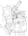
この結果、駆動用油圧ポンプ2がポンプ機能を奏して、この駆動用油圧ポンプ2内で昇圧したオイルを吐出することができる。なお、前記駆動用油圧ポンプ2としては、吐出圧力が、8kgf/cm2 以上で150kgf/cm2 以下のもの、より好ましくは、10kgf/cm2 以上で50kgf/cm2 以下のもの、この実施例では、吐出圧力が10kgf/cm2 〜20kgf/cm2 の、ギヤポンプ型の油圧ポンプが使用されている。しかし、ポンプの形式としては、このギヤポンプの形態の油圧ポンプに限定されるものでなく、他の形式の油圧ポンプであってもよい。
そして、前記アクチュエータ20の圧油吐出口20Bは、前記切替バルブ16を経て、前記オイルタンク14と接続されているリターンパイプ13の先端と接続されている。
また、前記切替バルブ16は、制御装置40(この実施例では、ECU(エンジン・コントロール・ユニット)が制御装置40として機能している)と制御線42で接続され、該制御装置40からの制御によって、開閉操作がなされて、前記駆動用油圧ポンプ2から昇圧された圧油が前記アクチュエータ20へ供給され、あるいは該駆動用油圧ポンプ2とアクチュエータ20との流路が遮断されるよう構成されている。
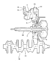
自動二輪車60(図3参照)のエンジン1が稼働状態においては、前記駆動用油圧ポンプ2の回転軸2Aがクランクシャフト1Dの回転数に比べて減速された状態で回転させられ、従って、この駆動用油圧ポンプ2の吐出口2oから所定圧に昇圧された圧油が、アキュムレータ15へ供給される。そして、アキュムレータ15が所定圧以上になると、図示しない該アキュムレータ15のリリーフバルブが開いて、前記駆動用油圧ポンプ2からの圧油は、アキュムレータ15から前記オイルタンク14側へ戻され、この結果、アキュムレータ15には常に所定圧力に維持された圧油が蓄積されている。
このような状態において、前記可変カム機構30のアクチュエータ20を操作させなければならない場合には、前記制御装置40が、前記切替バルブ16を制御して、該切替バルブ16のバルブを「開」の状態にする。この結果、前記アクチュエータ20がアキュムレータ15側と連通して、該アキュムレータ15側からアクチュエータ20へ前記した所定圧に維持された圧油が供給され、該アクチュエータ20が動作する。この結果、可変カム機構30の可変部分が動作して、該可変カム機構30の給排気バルブのカムを所定の状態に偏位させ、そのときのエンジン1の状態に対して適正な状態に変更する。そして、前記動作は、従来の潤滑用油圧ポンプに比べて、高い圧力(約2〜5倍)でおこなわれるため、迅速に且つ確実におこなわれる。
また、前記アクチュエータ20が、クラッチを駆動するための駆動用アクチュエータ、スロットルボディのスロットルバルブを駆動(開閉)するための駆動用のアクチュエータとして、使用されている場合にも、前記可変カム機構30の場合と同様に使用することができ、所謂「フライ・バイ・ワイヤ」でクラッチ、スロットルバルブを操作することができる。かかる場合には、小さな操作力で、迅速な操作が可能となる。
また、前記アクチュエータ20が、可変サスペンションを駆動するための駆動用アクチュエータとして、使用されている場合にも、前記可変カム機構30の場合と同様に使用することができ、走行中にもサスペンションの硬さ(長さ)を調節することができる。かかる場合には、走行中にサスペンションの硬さを調節でき、最適なコーナリングあるいはブレーキング特性を得ることが可能となる。
2…駆動用油圧ポンプ
20…アクチュエータ
50…潤滑オイルポンプ
Claims (7)
- エンジン各部へ潤滑油を供給する潤滑用オイルポンプを備えたレジャービィークル用エンジンであって、
前記潤滑用オイルポンプとは別に、該潤滑用オイルポンプの供給圧力より高い供給圧力で動作するアクチュエータを駆動するための、該潤滑用オイルポンプの吐出圧力より高い吐出圧力を有する駆動用油圧ポンプを設けたことを特徴とするレジャービィークル用エンジン。 - 前記駆動用油圧ポンプの吐出圧力が、少なくとも8kgf/cm2 以上で150kgf/cm2 以下であることを特徴とする請求項1記載のレジャービィークル用エンジン。
- レジャービィークルの原動機として使用されるレジャービィークル用エンジンであって、
大きな供給圧力を必要とするアクチュエータを駆動するための、少なくとも8kgf/cm2 以上で150kgf/cm2 以下の吐出圧力を有する駆動用油圧ポンプを、エンジンに設けたことを特徴とするレジャービィークル用エンジン。 - 前記駆動用油圧ポンプが、エンジンのクランクケースから上方へ延設されているシリンダに近接した、該クランクケース上方の位置に、配置されていることを特徴とする請求項1〜3のいずれか1の項に記載のレジャービィークル用エンジン。
- 前記駆動用油圧ポンプの配置位置が、エンジンの重心あるいはその近傍であることを特徴とする請求項4記載のレジャービィークル用エンジン。
- 前記駆動用油圧ポンプが、エンジンの出力軸に配置された出力ギヤと噛合する変速機の入力軸に配置されたプライマリギヤと同体的に回転するドライブギヤから、該駆動用油圧ポンプの回転軸に取着されたドリブンギヤを介して、減速して駆動されることを特徴とする請求項1〜5のいずれか1の項に記載のレジャービィークル用エンジン。
- 前記アクチュエータが、エンジンの可変バルブ機構の駆動用アクチュエータであることを特徴とする請求項1〜6のいずれか1の項に記載のレジャービィークル用エンジン。
Priority Applications (2)
| Application Number | Priority Date | Filing Date | Title |
|---|---|---|---|
| JP2005015251A JP4473740B2 (ja) | 2005-01-24 | 2005-01-24 | レジャービィークル用エンジン |
| US11/336,645 US7395798B2 (en) | 2005-01-24 | 2006-01-20 | Engine for leisure vehicle with lubricating oil pump and actuator drive oil pump |
Applications Claiming Priority (1)
| Application Number | Priority Date | Filing Date | Title |
|---|---|---|---|
| JP2005015251A JP4473740B2 (ja) | 2005-01-24 | 2005-01-24 | レジャービィークル用エンジン |
Publications (2)
| Publication Number | Publication Date |
|---|---|
| JP2006200499A true JP2006200499A (ja) | 2006-08-03 |
| JP4473740B2 JP4473740B2 (ja) | 2010-06-02 |
Family
ID=36778643
Family Applications (1)
| Application Number | Title | Priority Date | Filing Date |
|---|---|---|---|
| JP2005015251A Expired - Fee Related JP4473740B2 (ja) | 2005-01-24 | 2005-01-24 | レジャービィークル用エンジン |
Country Status (2)
| Country | Link |
|---|---|
| US (1) | US7395798B2 (ja) |
| JP (1) | JP4473740B2 (ja) |
Cited By (4)
| Publication number | Priority date | Publication date | Assignee | Title |
|---|---|---|---|---|
| JP2009085109A (ja) * | 2007-09-29 | 2009-04-23 | Honda Motor Co Ltd | 小型車両用パワーユニット |
| JP2009085110A (ja) * | 2007-09-29 | 2009-04-23 | Honda Motor Co Ltd | 小型車両用パワーユニット |
| JP2012062889A (ja) * | 2010-09-14 | 2012-03-29 | General Electric Co <Ge> | 油ワニス軽減システム |
| US8166933B2 (en) | 2007-09-29 | 2012-05-01 | Honda Motor Co., Ltd. | Power unit for small-sized vehicle |
Families Citing this family (2)
| Publication number | Priority date | Publication date | Assignee | Title |
|---|---|---|---|---|
| JP2018086887A (ja) * | 2016-11-28 | 2018-06-07 | ヤマハ発動機株式会社 | 鞍乗型車両 |
| CN111608761B (zh) * | 2020-06-02 | 2022-06-07 | 四川省天域航通科技有限公司 | 一种大型货运无人机润油系统 |
Family Cites Families (14)
| Publication number | Priority date | Publication date | Assignee | Title |
|---|---|---|---|---|
| US4206728A (en) * | 1978-05-01 | 1980-06-10 | General Motors Corporation | Hydraulic valve actuator system |
| JPS60155709A (ja) | 1984-01-20 | 1985-08-15 | Teijin Ltd | 走行糸条の油剤付着量監視方法 |
| US5537976A (en) * | 1995-08-08 | 1996-07-23 | Diesel Engine Retarders, Inc. | Four-cycle internal combustion engines with two-cycle compression release braking |
| DE69611916T2 (de) * | 1995-08-08 | 2001-06-21 | Diesel Engine Retarders,Inc. | Ein motorbremssystem durch dekompression für eine brennkraftmaschine |
| US6125828A (en) * | 1995-08-08 | 2000-10-03 | Diesel Engine Retarders, Inc. | Internal combustion engine with combined cam and electro-hydraulic engine valve control |
| JP3600397B2 (ja) * | 1997-03-19 | 2004-12-15 | 株式会社日立ユニシアオートモティブ | 内燃機関のバルブタイミング制御装置 |
| JP4555418B2 (ja) * | 1999-10-05 | 2010-09-29 | 本田技研工業株式会社 | 車両の動力伝達装置 |
| JP2001342812A (ja) * | 2000-05-31 | 2001-12-14 | Sanshin Ind Co Ltd | 船外機用4サイクルエンジン |
| JP4086488B2 (ja) * | 2001-09-19 | 2008-05-14 | 本田技研工業株式会社 | 油圧式自動変速機付き内燃機関 |
| US6871620B2 (en) * | 2002-04-09 | 2005-03-29 | Ford Global Technologies, Llc | Variable cam timing unit oil supply arrangement |
| US6769405B2 (en) * | 2002-07-31 | 2004-08-03 | Caterpillar Inc | Engine with high efficiency hydraulic system having variable timing valve actuation |
| US6736091B1 (en) * | 2003-01-06 | 2004-05-18 | Ford Global Technologies, Llc | Variable compression ratio control system for internal combustion engine |
| US6886523B2 (en) * | 2003-03-28 | 2005-05-03 | Tecumseh Products Company | Engine and pump assembly having combined housing |
| US6758184B1 (en) * | 2003-06-05 | 2004-07-06 | Delphi Technologies, Inc. | Method and apparatus for reducing oscillatory camshaft torque in an internal combustion engine |
-
2005
- 2005-01-24 JP JP2005015251A patent/JP4473740B2/ja not_active Expired - Fee Related
-
2006
- 2006-01-20 US US11/336,645 patent/US7395798B2/en not_active Expired - Fee Related
Cited By (4)
| Publication number | Priority date | Publication date | Assignee | Title |
|---|---|---|---|---|
| JP2009085109A (ja) * | 2007-09-29 | 2009-04-23 | Honda Motor Co Ltd | 小型車両用パワーユニット |
| JP2009085110A (ja) * | 2007-09-29 | 2009-04-23 | Honda Motor Co Ltd | 小型車両用パワーユニット |
| US8166933B2 (en) | 2007-09-29 | 2012-05-01 | Honda Motor Co., Ltd. | Power unit for small-sized vehicle |
| JP2012062889A (ja) * | 2010-09-14 | 2012-03-29 | General Electric Co <Ge> | 油ワニス軽減システム |
Also Published As
| Publication number | Publication date |
|---|---|
| US7395798B2 (en) | 2008-07-08 |
| JP4473740B2 (ja) | 2010-06-02 |
| US20060174848A1 (en) | 2006-08-10 |
Similar Documents
| Publication | Publication Date | Title |
|---|---|---|
| US7513812B1 (en) | Marine engine | |
| US6544086B2 (en) | Four stroke engine with cooling system | |
| US6725958B2 (en) | Snowmobile | |
| US7334556B2 (en) | Engine configuration for a motorcycle | |
| US6715460B2 (en) | Lubrication system for snowmobile engine | |
| US6443263B1 (en) | Oil tank for an internal combustion engine | |
| US6884131B2 (en) | Shift mechanism for marine propulsion unit | |
| JP4473740B2 (ja) | レジャービィークル用エンジン | |
| US20050120994A1 (en) | Internal combustion engine including splash-resistant oil storage structure | |
| JP4512011B2 (ja) | 内燃機関 | |
| JP2007182833A (ja) | エンジン | |
| US7147077B2 (en) | Engine starter mechanism arrangement for snow vehicles | |
| US8381698B2 (en) | Vehicle provided with engine and engine | |
| JP4519747B2 (ja) | 小型内燃機関 | |
| JP7300559B2 (ja) | ハイブリッド車両 | |
| JP6273534B2 (ja) | パワーユニットのオイル供給系構造 | |
| JPH0443857A (ja) | 自動二輪車用エンジンの吸気装置 | |
| US7036470B2 (en) | Four-cycle engine | |
| JP2014080895A (ja) | 内燃機関 | |
| EP1785611B1 (en) | Oil pump arrangement for an internal combustion engine | |
| JPH09317431A (ja) | 小型滑走艇の内燃機関 | |
| US6474286B2 (en) | Lubricant filler structure | |
| JP2002255094A (ja) | エンジンの動力伝達装置 |
Legal Events
| Date | Code | Title | Description |
|---|---|---|---|
| A621 | Written request for application examination |
Free format text: JAPANESE INTERMEDIATE CODE: A621 Effective date: 20070730 |
|
| A977 | Report on retrieval |
Free format text: JAPANESE INTERMEDIATE CODE: A971007 Effective date: 20091106 |
|
| A131 | Notification of reasons for refusal |
Free format text: JAPANESE INTERMEDIATE CODE: A131 Effective date: 20091110 |
|
| A521 | Written amendment |
Free format text: JAPANESE INTERMEDIATE CODE: A523 Effective date: 20100105 |
|
| TRDD | Decision of grant or rejection written | ||
| A01 | Written decision to grant a patent or to grant a registration (utility model) |
Free format text: JAPANESE INTERMEDIATE CODE: A01 Effective date: 20100302 |
|
| A01 | Written decision to grant a patent or to grant a registration (utility model) |
Free format text: JAPANESE INTERMEDIATE CODE: A01 |
|
| A61 | First payment of annual fees (during grant procedure) |
Free format text: JAPANESE INTERMEDIATE CODE: A61 Effective date: 20100305 |
|
| FPAY | Renewal fee payment (event date is renewal date of database) |
Free format text: PAYMENT UNTIL: 20130312 Year of fee payment: 3 |
|
| R150 | Certificate of patent or registration of utility model |
Ref document number: 4473740 Country of ref document: JP Free format text: JAPANESE INTERMEDIATE CODE: R150 Free format text: JAPANESE INTERMEDIATE CODE: R150 |
|
| FPAY | Renewal fee payment (event date is renewal date of database) |
Free format text: PAYMENT UNTIL: 20130312 Year of fee payment: 3 |
|
| FPAY | Renewal fee payment (event date is renewal date of database) |
Free format text: PAYMENT UNTIL: 20140312 Year of fee payment: 4 |
|
| FPAY | Renewal fee payment (event date is renewal date of database) |
Free format text: PAYMENT UNTIL: 20150312 Year of fee payment: 5 |
|
| LAPS | Cancellation because of no payment of annual fees |