JP2006200618A - 歯車、歯車ユニット、定着装置及び画像形成装置 - Google Patents
歯車、歯車ユニット、定着装置及び画像形成装置 Download PDFInfo
- Publication number
- JP2006200618A JP2006200618A JP2005012585A JP2005012585A JP2006200618A JP 2006200618 A JP2006200618 A JP 2006200618A JP 2005012585 A JP2005012585 A JP 2005012585A JP 2005012585 A JP2005012585 A JP 2005012585A JP 2006200618 A JP2006200618 A JP 2006200618A
- Authority
- JP
- Japan
- Prior art keywords
- gear
- impeller
- main body
- roll
- image forming
- Prior art date
- Legal status (The legal status is an assumption and is not a legal conclusion. Google has not performed a legal analysis and makes no representation as to the accuracy of the status listed.)
- Pending
Links
- 238000010438 heat treatment Methods 0.000 claims description 16
- 239000011347 resin Substances 0.000 abstract description 2
- 229920005989 resin Polymers 0.000 abstract description 2
- 230000003287 optical effect Effects 0.000 description 5
- 238000004140 cleaning Methods 0.000 description 3
- 238000001816 cooling Methods 0.000 description 3
- 238000000034 method Methods 0.000 description 3
- 230000004048 modification Effects 0.000 description 2
- 238000012986 modification Methods 0.000 description 2
- 238000011144 upstream manufacturing Methods 0.000 description 2
- 238000010586 diagram Methods 0.000 description 1
- 230000002093 peripheral effect Effects 0.000 description 1
- 230000002787 reinforcement Effects 0.000 description 1
Images


Landscapes
- Fixing For Electrophotography (AREA)
- Electrophotography Configuration And Component (AREA)
- Control Or Security For Electrophotography (AREA)
- Gears, Cams (AREA)
Abstract
【解決手段】 歯車76は、同軸で回転する歯車本体80及び羽根車82を有し、羽根車82の回転方向側面には複数の羽根84が設けられている。歯車本体80は、例えば平歯又はハス歯が周囲に設けられ、駆動力を伝達することができるようにされている。また、歯車本体80と羽根車82とは、互いに内径部分が連結部86によって連結されており、この連結部86を軸として一体に回転する。なお、歯車本体80と羽根車82とは、例えば溶融樹脂により一体に成型されてもよい。
【選択図】 図3
Description
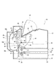
図1において、本発明の実施形態に係る画像形成装置10の概要が示されている。画像形成装置10は、画像形成装置本体12を有し、この画像形成装置本体12内に像形成手段14が搭載され、この画像形成装置本体12の上部に後述する排出部16が設けられていると共に、この画像形成装置本体12の下部に例えば2段の給紙ユニット18,18が配置されている。さらに、画像形成装置本体12の下方には、オプションとして複数の給紙ユニットが配置できるようにしてある。
尚、この実施形態においては、光書込み装置58として走査型のレーザ露光装置を用いたが、他の実施形態としてLEDや面発光レーザ等を用いることができる。
図2において、定着装置36に対して駆動力を伝達する歯車ユニット70及びその周辺が示されいる。加熱ロール37は、一端に歯車66が設けられており、モータ68の駆動力が歯車ユニット70を介して伝達されるようになっている。歯車ユニット70は、例えば歯車72,74,76を有し、モータ68の一端に固定された歯車78の駆動力を歯車72,74,76の順に伝達し、歯車76が歯車66に駆動力を伝達することにより、加熱ロール37を回転させる。加圧ロール38は、上述したように加熱ロール37に対して圧接されており、加熱ロール37の回転に従動するようにされている。
画像形成信号が送られると、像担持体44が帯電装置56により一様に帯電され、この帯電された像担持体44には、画像信号に基づいて静電潜像が形成される。光書込み装置58により形成された像担持体44の静電潜像は現像機60の現像剤により可視化される。
現像剤が定着した用紙は、排出ロール40により排出口34から排出部16へ排出される。ただし、両面印刷の場合は、反転路に戻され、再びレジストロール39、転写装置42と像担持体44及び定着装置36を通って排出口34から排出部16へ排出される。
図4において、歯車76の変形例が示されている。歯車76の変形例は、同軸で回転する歯車本体80及び羽根車82を有し、羽根車82の軸方向端面にには複数の羽根84が設けられている。このように、ユーザは、歯車76の羽根84の大きさ及び位置などを任意に設定することができる。
36 定着装置
37 加熱ロール
38 加圧ロール
66,72,74,76,78 歯車
68 モータ
70 歯車ユニット
80 歯車本体
82 羽根車
84 羽根
86 連結部
Claims (7)
- 歯車本体と、1つ以上の羽根を具備し、前記歯車本体と同軸で回転する羽根車とを有し、前記歯車本体と前記羽根車とは連結されていることを特徴とする歯車。
- 前記歯車本体及び前記羽根車は、互いに内径部分が連結されていることを特徴とする請求項1記載の歯車。
- 前記歯車本体及び前記羽根車は、一体に成型されてなることを特徴とする請求項1又は2記載の歯車。
- 複数の歯車を有する歯車ユニットにおいて、前記歯車の少なくともいずれかは、歯車本体と、1つ以上の羽根を具備し、前記歯車本体と同軸で回転する羽根車とを有し、前記歯車本体と前記羽根車とは連結されていることを特徴とする歯車ユニット。
- 前記歯車本体及び前記羽根車を有する前記歯車の少なくともいずれかは、他の前記歯車よりも発熱体に近い位置に配設されることを特徴とする請求項4記載の歯車ユニット。
- 用紙に現像剤を定着させる定着装置であって、歯車本体と、1つ以上の羽根を具備し、前記歯車本体と同軸で回転する羽根車とを有し、前記歯車本体と前記羽根車とが連結されている歯車を有することを特徴とする定着装置。
- 請求項6記載の定着装置を有する画像形成装置。
Priority Applications (1)
| Application Number | Priority Date | Filing Date | Title |
|---|---|---|---|
| JP2005012585A JP2006200618A (ja) | 2005-01-20 | 2005-01-20 | 歯車、歯車ユニット、定着装置及び画像形成装置 |
Applications Claiming Priority (1)
| Application Number | Priority Date | Filing Date | Title |
|---|---|---|---|
| JP2005012585A JP2006200618A (ja) | 2005-01-20 | 2005-01-20 | 歯車、歯車ユニット、定着装置及び画像形成装置 |
Publications (1)
| Publication Number | Publication Date |
|---|---|
| JP2006200618A true JP2006200618A (ja) | 2006-08-03 |
Family
ID=36958800
Family Applications (1)
| Application Number | Title | Priority Date | Filing Date |
|---|---|---|---|
| JP2005012585A Pending JP2006200618A (ja) | 2005-01-20 | 2005-01-20 | 歯車、歯車ユニット、定着装置及び画像形成装置 |
Country Status (1)
| Country | Link |
|---|---|
| JP (1) | JP2006200618A (ja) |
Cited By (1)
| Publication number | Priority date | Publication date | Assignee | Title |
|---|---|---|---|---|
| JP2010072343A (ja) * | 2008-09-18 | 2010-04-02 | Konica Minolta Business Technologies Inc | 駆動伝達機構及び画像形成装置 |
Citations (3)
| Publication number | Priority date | Publication date | Assignee | Title |
|---|---|---|---|---|
| JPS61109466U (ja) * | 1984-12-21 | 1986-07-11 | ||
| JPH04102754A (ja) * | 1990-08-21 | 1992-04-03 | Fujitsu Ltd | 回転体の構造 |
| JPH06194920A (ja) * | 1992-12-25 | 1994-07-15 | Canon Inc | 画像形成装置 |
-
2005
- 2005-01-20 JP JP2005012585A patent/JP2006200618A/ja active Pending
Patent Citations (3)
| Publication number | Priority date | Publication date | Assignee | Title |
|---|---|---|---|---|
| JPS61109466U (ja) * | 1984-12-21 | 1986-07-11 | ||
| JPH04102754A (ja) * | 1990-08-21 | 1992-04-03 | Fujitsu Ltd | 回転体の構造 |
| JPH06194920A (ja) * | 1992-12-25 | 1994-07-15 | Canon Inc | 画像形成装置 |
Cited By (1)
| Publication number | Priority date | Publication date | Assignee | Title |
|---|---|---|---|---|
| JP2010072343A (ja) * | 2008-09-18 | 2010-04-02 | Konica Minolta Business Technologies Inc | 駆動伝達機構及び画像形成装置 |
Similar Documents
| Publication | Publication Date | Title |
|---|---|---|
| CN102109797B (zh) | 显影盒 | |
| JP4919124B2 (ja) | カートリッジ | |
| US20140178105A1 (en) | Developing Cartridge | |
| US7760216B2 (en) | Sheet feeding mechanism with duplex print function and related printer | |
| JP2010107694A (ja) | 画像形成装置 | |
| US20140105662A1 (en) | Image forming device and development unit attachable thereto | |
| US9285769B2 (en) | Image forming apparatus including a duct for airflow having a sectional area that becomes gradually smaller toward a part of a rotating shaft exposed into the duct | |
| JP2014102340A (ja) | トナー容器及び画像形成装置 | |
| JP2002258674A (ja) | 電子写真画像形成装置 | |
| JP6617687B2 (ja) | 画像形成装置 | |
| JP5193247B2 (ja) | ホルダと感光体の冷却構造及びこれを備えた画像形成装置 | |
| JP4161650B2 (ja) | 画像形成装置 | |
| JP2015189579A (ja) | 画像形成装置 | |
| JP2016018067A (ja) | 画像形成装置 | |
| JP2014145794A (ja) | 現像装置 | |
| JP2008051937A (ja) | 画像形成装置 | |
| JP6614111B2 (ja) | 画像形成装置 | |
| JP4314510B2 (ja) | 定着装置用ヒータ保持部材、定着装置及び画像形成装置 | |
| JP4823757B2 (ja) | 駆動ユニットと被駆動ユニットを有する装置 | |
| JP5365506B2 (ja) | 現像カートリッジ | |
| JP2006208641A (ja) | 画像形成装置 | |
| JP2008168472A (ja) | 光走査装置およびこれを有する画像形成装置 | |
| JP2024122731A (ja) | 画像形成装置 | |
| JP2006201441A (ja) | 画像形成装置 | |
| JP2012208320A (ja) | 画像形成装置 |
Legal Events
| Date | Code | Title | Description |
|---|---|---|---|
| A621 | Written request for application examination |
Free format text: JAPANESE INTERMEDIATE CODE: A621 Effective date: 20071219 |
|
| A977 | Report on retrieval |
Free format text: JAPANESE INTERMEDIATE CODE: A971007 Effective date: 20100119 |
|
| A131 | Notification of reasons for refusal |
Free format text: JAPANESE INTERMEDIATE CODE: A131 Effective date: 20100121 |
|
| A521 | Written amendment |
Free format text: JAPANESE INTERMEDIATE CODE: A523 Effective date: 20100316 |
|
| A131 | Notification of reasons for refusal |
Free format text: JAPANESE INTERMEDIATE CODE: A131 Effective date: 20100708 |
|
| A02 | Decision of refusal |
Free format text: JAPANESE INTERMEDIATE CODE: A02 Effective date: 20101104 |