JP2006200744A - ロープブレーキ装置 - Google Patents
ロープブレーキ装置 Download PDFInfo
- Publication number
- JP2006200744A JP2006200744A JP2006011463A JP2006011463A JP2006200744A JP 2006200744 A JP2006200744 A JP 2006200744A JP 2006011463 A JP2006011463 A JP 2006011463A JP 2006011463 A JP2006011463 A JP 2006011463A JP 2006200744 A JP2006200744 A JP 2006200744A
- Authority
- JP
- Japan
- Prior art keywords
- rope
- brake
- brake element
- holes
- pieces
- Prior art date
- Legal status (The legal status is an assumption and is not a legal conclusion. Google has not performed a legal analysis and makes no representation as to the accuracy of the status listed.)
- Granted
Links
Images

Classifications
-
- F—MECHANICAL ENGINEERING; LIGHTING; HEATING; WEAPONS; BLASTING
- F16—ENGINEERING ELEMENTS AND UNITS; GENERAL MEASURES FOR PRODUCING AND MAINTAINING EFFECTIVE FUNCTIONING OF MACHINES OR INSTALLATIONS; THERMAL INSULATION IN GENERAL
- F16G—BELTS, CABLES, OR ROPES, PREDOMINANTLY USED FOR DRIVING PURPOSES; CHAINS; FITTINGS PREDOMINANTLY USED THEREFOR
- F16G11/00—Means for fastening cables or ropes to one another or to other objects; Caps or sleeves for fixing on cables or ropes
- F16G11/14—Devices or coupling-pieces designed for easy formation of adjustable loops, e.g. choker hooks; Hooks or eyes with integral parts designed to facilitate quick attachment to cables or ropes at any point, e.g. by forming loops
- F16G11/146—Eyes
-
- F—MECHANICAL ENGINEERING; LIGHTING; HEATING; WEAPONS; BLASTING
- F16—ENGINEERING ELEMENTS AND UNITS; GENERAL MEASURES FOR PRODUCING AND MAINTAINING EFFECTIVE FUNCTIONING OF MACHINES OR INSTALLATIONS; THERMAL INSULATION IN GENERAL
- F16G—BELTS, CABLES, OR ROPES, PREDOMINANTLY USED FOR DRIVING PURPOSES; CHAINS; FITTINGS PREDOMINANTLY USED THEREFOR
- F16G11/00—Means for fastening cables or ropes to one another or to other objects; Caps or sleeves for fixing on cables or ropes
- F16G11/04—Means for fastening cables or ropes to one another or to other objects; Caps or sleeves for fixing on cables or ropes with wedging action, e.g. friction clamps
- F16G11/044—Means for fastening cables or ropes to one another or to other objects; Caps or sleeves for fixing on cables or ropes with wedging action, e.g. friction clamps friction clamps deforming the cable, wire, rope or cord
- F16G11/046—Means for fastening cables or ropes to one another or to other objects; Caps or sleeves for fixing on cables or ropes with wedging action, e.g. friction clamps friction clamps deforming the cable, wire, rope or cord by bending the cable around a surface
Landscapes
- Engineering & Computer Science (AREA)
- General Engineering & Computer Science (AREA)
- Mechanical Engineering (AREA)
- Braking Arrangements (AREA)
Abstract
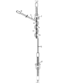
【解決手段】ブレーキプレート3が、複数列状に相前後して位置する複数の孔4を備えていて、一方の端部で、ロープブレーキエレメントの第1の接続箇所1を備えており、ロープブレーキエレメントの、反対側の第2の接続箇所2で、互いに結合された複数のロープ片5,6が設けられており、各ロープ片が、順次設けられた孔に対するロープ片の貫通案内方向を変えて、それぞれ1列の、相前後して位置する孔の成す孔列を通って案内されている。
【選択図】図1
Description
Claims (3)
- ロープブレーキ装置であって、
2つの接続箇所の間に配置されたロープブレーキエレメントを備えており、該ロープブレーキエレメントが、孔を備えたブレーキプレートと、孔を通って抵抗下で引っ張られる少なくとも1つのロープとを備えている形式のものにおいて、
ブレーキプレート(3)が、複数列状に相前後して位置する複数の孔(4)を備えていて、かつ一方の端部で、ロープブレーキエレメントの第1の接続箇所(1)を備えており、ロープブレーキエレメントの、第1の接続箇所(1)とは反対側の第2の接続箇所(2)で、互いに結合された複数のロープ片(5,6)が設けられており、各ロープ片(5,6)が、順次設けられた孔(4)に対するロープ片の貫通案内方向を変えて、それぞれ1列の、相前後して位置する孔(4)の成す孔列を通って案内されていることを特徴とする、ロープブレーキ装置。 - ロープブレーキエレメントの第2の接続箇所(2)におけるロープ片(5,6)の結合が、対偶を成して形成されたループによって行われている、請求項1記載のロープブレーキ装置。
- ブレーキプレート(3)の最後位の孔(4)から突出するロープ片(5,6)の長さが、ロープブレーキエレメントの制動区間を規定しており、ロープ片(5,6)の端部が、ストッパ片として作用するクランププレス部(8)によって終了している、請求項1記載のロープブレーキ装置。
Applications Claiming Priority (2)
| Application Number | Priority Date | Filing Date | Title |
|---|---|---|---|
| CH00086/05 | 2005-01-20 | ||
| CH00086/05A CH697305B1 (de) | 2005-01-20 | 2005-01-20 | Seilbremsanordnung. |
Publications (2)
| Publication Number | Publication Date |
|---|---|
| JP2006200744A true JP2006200744A (ja) | 2006-08-03 |
| JP4847760B2 JP4847760B2 (ja) | 2011-12-28 |
Family
ID=36686516
Family Applications (1)
| Application Number | Title | Priority Date | Filing Date |
|---|---|---|---|
| JP2006011463A Expired - Lifetime JP4847760B2 (ja) | 2005-01-20 | 2006-01-19 | ロープブレーキ装置 |
Country Status (5)
| Country | Link |
|---|---|
| JP (1) | JP4847760B2 (ja) |
| AT (1) | AT501342A3 (ja) |
| CH (1) | CH697305B1 (ja) |
| DE (1) | DE102005053704A1 (ja) |
| IT (1) | ITMI20052442A1 (ja) |
Families Citing this family (8)
| Publication number | Priority date | Publication date | Assignee | Title |
|---|---|---|---|---|
| CH701591B1 (de) | 2007-10-18 | 2011-02-15 | Geobrugg Ag | Bremsvorrichtung. |
| EP2607746A1 (de) | 2011-12-19 | 2013-06-26 | Isofer AG | Seilbremsanordnung |
| ITTO20120432A1 (it) * | 2012-05-14 | 2013-11-15 | Incofil Srl | Dispositivo frenante a fune d'attrito e dissipatore metallico a deformazione plastica. |
| FR3000953B1 (fr) * | 2013-01-15 | 2017-06-16 | Can | Dispositif de freinage et systeme de protection comprenant un tel dispositif de freinage |
| EP3162960B1 (de) | 2015-10-30 | 2018-04-11 | Christian Schneider | Seilbremsanordnung |
| DE202018102224U1 (de) * | 2018-04-20 | 2019-07-23 | Philipp Gmbh | Transportanker |
| CN114084826B (zh) * | 2021-11-12 | 2023-05-09 | 北京紫竹慧建设服务股份有限公司 | 卷扬钢丝绳的更换装置以及更换方法 |
| IT202300000306A1 (it) * | 2023-01-12 | 2024-07-12 | Maccaferri Off Spa | Dispositivo dissipatore d'energia a fune d'attrito per una struttura di protezione |
Citations (6)
| Publication number | Priority date | Publication date | Assignee | Title |
|---|---|---|---|---|
| JPS486463Y1 (ja) * | 1969-02-05 | 1973-02-19 | ||
| JPS5287875A (en) * | 1976-01-16 | 1977-07-22 | Nippon Electric Co | Discharge lamp ignition device |
| JPS58157480A (ja) * | 1982-03-13 | 1983-09-19 | 五十嵐工業株式会社 | 模型船舶 |
| JPS62191115A (ja) * | 1986-02-18 | 1987-08-21 | Toshiba Mach Co Ltd | 射出成形機の金型交換装置 |
| EP0531574A1 (de) * | 1991-09-13 | 1993-03-17 | Iako S.A. | Seilbremse für ein Befestigungsseil zum Fixieren eines Fangnetzes, insbesondere Steinschlagnetzes |
| JPH09156886A (ja) * | 1995-12-07 | 1997-06-17 | Arakawa Giken Kogyo Kk | 物品吊下装置 |
Family Cites Families (3)
| Publication number | Priority date | Publication date | Assignee | Title |
|---|---|---|---|---|
| GB572727A (en) * | 1938-09-14 | 1945-10-22 | Aviorex Dreyfus Freres L | Improvements in or relating to shock-absorbing devices for parachutes for absorbing the shock on opening |
| JPS5321338B2 (ja) * | 1973-02-12 | 1978-07-01 | ||
| DE29819485U1 (de) * | 1998-11-02 | 1999-03-18 | Konzok, Michael, 27777 Ganderkesee | Luftschleppvorrichtung, insbesondere zur Luftwerbung |
-
2005
- 2005-01-20 CH CH00086/05A patent/CH697305B1/de not_active IP Right Cessation
- 2005-11-10 DE DE102005053704A patent/DE102005053704A1/de not_active Withdrawn
- 2005-11-21 AT AT0189205A patent/AT501342A3/de active IP Right Grant
- 2005-12-22 IT IT002442A patent/ITMI20052442A1/it unknown
-
2006
- 2006-01-19 JP JP2006011463A patent/JP4847760B2/ja not_active Expired - Lifetime
Patent Citations (6)
| Publication number | Priority date | Publication date | Assignee | Title |
|---|---|---|---|---|
| JPS486463Y1 (ja) * | 1969-02-05 | 1973-02-19 | ||
| JPS5287875A (en) * | 1976-01-16 | 1977-07-22 | Nippon Electric Co | Discharge lamp ignition device |
| JPS58157480A (ja) * | 1982-03-13 | 1983-09-19 | 五十嵐工業株式会社 | 模型船舶 |
| JPS62191115A (ja) * | 1986-02-18 | 1987-08-21 | Toshiba Mach Co Ltd | 射出成形機の金型交換装置 |
| EP0531574A1 (de) * | 1991-09-13 | 1993-03-17 | Iako S.A. | Seilbremse für ein Befestigungsseil zum Fixieren eines Fangnetzes, insbesondere Steinschlagnetzes |
| JPH09156886A (ja) * | 1995-12-07 | 1997-06-17 | Arakawa Giken Kogyo Kk | 物品吊下装置 |
Also Published As
| Publication number | Publication date |
|---|---|
| AT501342A3 (de) | 2006-11-15 |
| CH697305B1 (de) | 2008-08-15 |
| JP4847760B2 (ja) | 2011-12-28 |
| DE102005053704A1 (de) | 2006-08-03 |
| AT501342A2 (de) | 2006-08-15 |
| ITMI20052442A1 (it) | 2006-07-21 |
Similar Documents
| Publication | Publication Date | Title |
|---|---|---|
| EP2109723B1 (en) | Wire termination device | |
| US6401309B1 (en) | Fastening hook for elastic rope | |
| CA2763476C (en) | Device for securing rope in multiple configurations and process of using the same | |
| JP4847760B2 (ja) | ロープブレーキ装置 | |
| US6880490B2 (en) | Dog collar having buckle | |
| US20120317892A1 (en) | Sheathing edge protector and roof safety anchor assembly incorporating the same | |
| US20160325130A1 (en) | Fastening system for a sports and recreational facility | |
| US20110297907A1 (en) | Shock-absorbing device for net body of guard fence | |
| US3090343A (en) | Cleat | |
| DE102014001695B3 (de) | Seilbremse zur Sicherung von Personen und Gegenständen, insbesondere Personen beim Klettern, die zur Verringerung der Energie im Sturzfall des Kletterers über ein Seil auf den Sichernden einwirkt. | |
| DE112016001527T5 (de) | Spannungsverifikationswerkzeug zum Zurren | |
| JP4886306B2 (ja) | ロープブレーキ装置 | |
| US20150074960A1 (en) | Carabiner with wire level for climbing | |
| US20080083134A1 (en) | Rope retainer | |
| JP2017514754A (ja) | 錨爪式埋設デバイス | |
| WO2005007952A3 (fr) | Cadre de lisses et metier a tisser equipe d'au moins un tel cadre | |
| US7137239B2 (en) | Prickle chain link | |
| EP2281717A2 (en) | Tightening cord provided with connecting means | |
| DE102011055590B4 (de) | Ringanker | |
| SE505370C2 (sv) | Spännorgan för snören, skoband, linor och liknande | |
| KR101073749B1 (ko) | 로프클립 | |
| US3171177A (en) | Conveyor and transmission belt connection | |
| WO2006000062A3 (fr) | Ensemble d’arrimage pour camion | |
| DE10134219A1 (de) | Chokerring | |
| ZA200506955B (en) | A rope locking device |
Legal Events
| Date | Code | Title | Description |
|---|---|---|---|
| A621 | Written request for application examination |
Free format text: JAPANESE INTERMEDIATE CODE: A621 Effective date: 20081015 |
|
| RD04 | Notification of resignation of power of attorney |
Free format text: JAPANESE INTERMEDIATE CODE: A7424 Effective date: 20101228 |
|
| A977 | Report on retrieval |
Free format text: JAPANESE INTERMEDIATE CODE: A971007 Effective date: 20110224 |
|
| A131 | Notification of reasons for refusal |
Free format text: JAPANESE INTERMEDIATE CODE: A131 Effective date: 20110302 |
|
| A601 | Written request for extension of time |
Free format text: JAPANESE INTERMEDIATE CODE: A601 Effective date: 20110527 |
|
| A602 | Written permission of extension of time |
Free format text: JAPANESE INTERMEDIATE CODE: A602 Effective date: 20110601 |
|
| A601 | Written request for extension of time |
Free format text: JAPANESE INTERMEDIATE CODE: A601 Effective date: 20110622 |
|
| A602 | Written permission of extension of time |
Free format text: JAPANESE INTERMEDIATE CODE: A602 Effective date: 20110627 |
|
| A601 | Written request for extension of time |
Free format text: JAPANESE INTERMEDIATE CODE: A601 Effective date: 20110802 |
|
| A602 | Written permission of extension of time |
Free format text: JAPANESE INTERMEDIATE CODE: A602 Effective date: 20110805 |
|
| TRDD | Decision of grant or rejection written | ||
| A01 | Written decision to grant a patent or to grant a registration (utility model) |
Free format text: JAPANESE INTERMEDIATE CODE: A01 Effective date: 20110930 |
|
| A01 | Written decision to grant a patent or to grant a registration (utility model) |
Free format text: JAPANESE INTERMEDIATE CODE: A01 |
|
| A61 | First payment of annual fees (during grant procedure) |
Free format text: JAPANESE INTERMEDIATE CODE: A61 Effective date: 20111014 |
|
| FPAY | Renewal fee payment (event date is renewal date of database) |
Free format text: PAYMENT UNTIL: 20141021 Year of fee payment: 3 |
|
| R150 | Certificate of patent or registration of utility model |
Ref document number: 4847760 Country of ref document: JP Free format text: JAPANESE INTERMEDIATE CODE: R150 Free format text: JAPANESE INTERMEDIATE CODE: R150 |
|
| R250 | Receipt of annual fees |
Free format text: JAPANESE INTERMEDIATE CODE: R250 |
|
| R250 | Receipt of annual fees |
Free format text: JAPANESE INTERMEDIATE CODE: R250 |
|
| R250 | Receipt of annual fees |
Free format text: JAPANESE INTERMEDIATE CODE: R250 |
|
| R250 | Receipt of annual fees |
Free format text: JAPANESE INTERMEDIATE CODE: R250 |
|
| S531 | Written request for registration of change of domicile |
Free format text: JAPANESE INTERMEDIATE CODE: R313531 |
|
| S533 | Written request for registration of change of name |
Free format text: JAPANESE INTERMEDIATE CODE: R313533 |
|
| R350 | Written notification of registration of transfer |
Free format text: JAPANESE INTERMEDIATE CODE: R350 |
|
| R250 | Receipt of annual fees |
Free format text: JAPANESE INTERMEDIATE CODE: R250 |
|
| R250 | Receipt of annual fees |
Free format text: JAPANESE INTERMEDIATE CODE: R250 |
|
| R250 | Receipt of annual fees |
Free format text: JAPANESE INTERMEDIATE CODE: R250 |
|
| R371 | Transfer withdrawn |
Free format text: JAPANESE INTERMEDIATE CODE: R371 |
|
| S111 | Request for change of ownership or part of ownership |
Free format text: JAPANESE INTERMEDIATE CODE: R313113 |
|
| S111 | Request for change of ownership or part of ownership |
Free format text: JAPANESE INTERMEDIATE CODE: R313113 |
|
| R250 | Receipt of annual fees |
Free format text: JAPANESE INTERMEDIATE CODE: R250 |
|
| R350 | Written notification of registration of transfer |
Free format text: JAPANESE INTERMEDIATE CODE: R350 |
|
| R250 | Receipt of annual fees |
Free format text: JAPANESE INTERMEDIATE CODE: R250 |
|
| R250 | Receipt of annual fees |
Free format text: JAPANESE INTERMEDIATE CODE: R250 |
|
| S111 | Request for change of ownership or part of ownership |
Free format text: JAPANESE INTERMEDIATE CODE: R313113 |
|
| R350 | Written notification of registration of transfer |
Free format text: JAPANESE INTERMEDIATE CODE: R350 |
|
| R250 | Receipt of annual fees |
Free format text: JAPANESE INTERMEDIATE CODE: R250 |
|
| R250 | Receipt of annual fees |
Free format text: JAPANESE INTERMEDIATE CODE: R250 |
|
| EXPY | Cancellation because of completion of term |