JP2006201045A - Uneven painting measuring instrument, measuring method, and evaluation method - Google Patents
Uneven painting measuring instrument, measuring method, and evaluation method Download PDFInfo
- Publication number
- JP2006201045A JP2006201045A JP2005013486A JP2005013486A JP2006201045A JP 2006201045 A JP2006201045 A JP 2006201045A JP 2005013486 A JP2005013486 A JP 2005013486A JP 2005013486 A JP2005013486 A JP 2005013486A JP 2006201045 A JP2006201045 A JP 2006201045A
- Authority
- JP
- Japan
- Prior art keywords
- optical unit
- reflected light
- coating
- light
- measuring
- Prior art date
- Legal status (The legal status is an assumption and is not a legal conclusion. Google has not performed a legal analysis and makes no representation as to the accuracy of the status listed.)
- Pending
Links
- 238000000034 method Methods 0.000 title claims abstract description 20
- 238000011156 evaluation Methods 0.000 title claims abstract description 19
- 238000010422 painting Methods 0.000 title abstract description 7
- 230000003287 optical effect Effects 0.000 claims abstract description 43
- 238000012545 processing Methods 0.000 claims abstract description 6
- 238000005259 measurement Methods 0.000 claims description 54
- 238000000576 coating method Methods 0.000 claims description 52
- 239000011248 coating agent Substances 0.000 claims description 50
- 238000013507 mapping Methods 0.000 claims description 11
- 238000001228 spectrum Methods 0.000 claims description 9
- 238000000691 measurement method Methods 0.000 claims description 4
- 229910052751 metal Inorganic materials 0.000 abstract description 6
- 239000002184 metal Substances 0.000 abstract description 6
- 230000000007 visual effect Effects 0.000 abstract description 6
- 230000001678 irradiating effect Effects 0.000 abstract description 3
- 239000003973 paint Substances 0.000 description 8
- 238000010586 diagram Methods 0.000 description 5
- 238000009792 diffusion process Methods 0.000 description 3
- 229910052782 aluminium Inorganic materials 0.000 description 2
- XAGFODPZIPBFFR-UHFFFAOYSA-N aluminium Chemical compound [Al] XAGFODPZIPBFFR-UHFFFAOYSA-N 0.000 description 2
- 239000000463 material Substances 0.000 description 2
- 229910000831 Steel Inorganic materials 0.000 description 1
- 238000013461 design Methods 0.000 description 1
- 239000010445 mica Substances 0.000 description 1
- 229910052618 mica group Inorganic materials 0.000 description 1
- 230000002093 peripheral effect Effects 0.000 description 1
- 229920000728 polyester Polymers 0.000 description 1
- 239000000843 powder Substances 0.000 description 1
- 238000011158 quantitative evaluation Methods 0.000 description 1
- 230000001953 sensory effect Effects 0.000 description 1
- 239000007787 solid Substances 0.000 description 1
- 239000010959 steel Substances 0.000 description 1
- 238000011179 visual inspection Methods 0.000 description 1
- XLYOFNOQVPJJNP-UHFFFAOYSA-N water Substances O XLYOFNOQVPJJNP-UHFFFAOYSA-N 0.000 description 1
Images




Landscapes
- Investigating Materials By The Use Of Optical Means Adapted For Particular Applications (AREA)
Abstract
Description
本発明は、メタリック塗装がなされた自動車などの計測対象物の平面だけでなく曲面においても、メタリック色の塗装ムラ(メタルムラ)を面情報として計測でき、目視評価との一致性が高い塗装ムラの計測装置、計測方法及び評価方法に関する。 The present invention is capable of measuring metallic paint unevenness (metal unevenness) as surface information not only on a flat surface but also a curved surface of a measurement object such as an automobile with metallic coating, and is highly consistent with visual evaluation. The present invention relates to a measurement device, a measurement method, and an evaluation method.
自動車外板などに形成される塗膜の意匠性を高めるため、近年ソリッドカラー仕上げに代えて、りん片状のアルミニウムや雲母粉末などの光輝材を含有せしめた塗料によるメタリック塗装が多く採用されている。 In recent years, in order to improve the design of paint films formed on automobile outer panels, metallic coatings with paints containing glitter materials such as flake-like aluminum and mica powder have been widely adopted instead of solid color finishing. Yes.
メタリック塗膜の光学的特性としては、明るさ(白さ)、方向性(フリップ・フロップ性)、スパークル感(キラキラ感)、塗装ムラ(メタルムラ)等が挙げられ、従来、これらはほとんど人間の目視による定性的な判断がなされており、特に、塗装ムラ(メタルムラ)については熟練者の判断によるところが多く、初心者でも判断可能な有効な計測方法が見いだされていなかった。 Optical properties of metallic coatings include brightness (whiteness), directionality (flip / flop), sparkle (glitter), coating unevenness (metal unevenness), and so on. Qualitative judgments have been made by visual inspection, and in particular, painting irregularities (metal irregularities) are often judged by skilled workers, and no effective measurement method that can be judged even by beginners has been found.
メタリック塗装時に発生する塗装ムラは、光輝材の配列乱れに起因するものであり、塗装ラインにおける塗装条件や塗料条件によって左右されることから、ライン管理の一環として塗装ムラの計測が求められている。 The coating unevenness that occurs during metallic coating is due to the disorder of the arrangement of the glitter material, and depends on the coating conditions and paint conditions in the coating line, so it is required to measure the coating unevenness as part of line management. .
そこで特許文献1〜特許文献3において、メタリック塗膜の塗装ムラ(メタルムラ感)の程度を客観的且つ定量的に計測、評価する方法が提案されている。
Therefore,
しかしながら特許文献1及び特許文献2の方法では、線状に測定点を採るために、目視評価のように塗装面全体からみて、どこにどの程度のムラが存在するかがわからないという問題があった。一方、特許文献3の装置では、塗装面としてのデータは取れるものの、曲面の多い被計測物については正確なデータが取れず実用性が低いという問題があった。
However, in the methods of
本発明の目的は、メタリック塗装がなされた自動車などの計測対象物の平面だけでなく曲面においても、メタリック色の塗装ムラ(メタルムラ)を塗装面全体で計測でき、目視評価との一致性が高い塗装ムラの計測装置、計測方法及び評価方法を提供することにある。 The object of the present invention is to measure the metallic coating unevenness (metal unevenness) on the entire painted surface not only on the flat surface but also on the curved surface of the object to be measured such as an automobile coated with metallic paint, which is highly consistent with the visual evaluation. An object of the present invention is to provide a coating unevenness measuring device, measuring method and evaluation method.
本発明は、
1.メタリック塗装面に光を照射し、正反射光が入射しない角度から受光した反射光強度を連続的に測定して該塗装面の塗装ムラを計測する装置であって、
前記塗装面に光を照射する発光素子及び該塗装面からの反射光を受光する受光素子を内蔵し、3つ又は4つのボールベアリングころによって支持された光学ユニットと、
該光学ユニットに具備された全てのボールベアリングころが前記塗装面に接触するように前記光学ユニットを保持可能で且つ前記塗装面上を移動可能とせしめるロボットと、
該ロボットの制御装置と、
前記光学ユニットによって測定された反射光強度を処理可能な処理装置とを具備する塗装ムラの計測装置、
2.光学ユニットを保持するロボットが、可動関節部を具備する2軸ロボットもしくはアームロボットである1項記載の計測装置、
3.メタリック塗装面に光を照射し、正反射光が入射しない角度から受光した反射光強度を連続的に測定する光学ユニットを用いて、該塗装面の塗装ムラを計測する方法であって、
該光学ユニットが、3つ又は4つのボールベアリングころを介して前記塗装面上に接触し且つ移動可能であり、
該光学ユニットを一定速度で前記塗装面上に対して略水平方向に往復移動させながら矩形に掃引して、計測対象面全体の塗装ムラの程度を2次元的に計測することを特徴とする塗装ムラの計測方法、
4.3項記載の方法によって測定された反射光強度のデータを、計測対象面全体について2次元マッピングしてなる画像から、計測対象面の塗装ムラを評価してなる塗装ムラの評価方法、
5.3項記載の方法によって測定された反射光強度のデータの標準偏差を用いて、計測対象面の塗装ムラを定量的に評価してなる塗装ムラの評価方法、
6.3項記載の方法によって測定された反射光強度のデータを、2次元フーリエ変換することにより得られる2次元パワースペクトルを用いて、計測対象面の塗装ムラを定量的に評価してなる塗装ムラの評価方法、
に関する。
The present invention
1. A device that irradiates light on a metallic coating surface and continuously measures reflected light intensity received from an angle at which regular reflection light does not enter to measure coating unevenness on the coating surface,
A light-emitting element that irradiates light on the painted surface and a light-receiving element that receives reflected light from the painted surface, and an optical unit supported by three or four ball bearing rollers;
A robot capable of holding the optical unit and moving on the painted surface so that all ball bearing rollers provided in the optical unit are in contact with the painted surface;
A control device for the robot;
A coating unevenness measuring device comprising a processing device capable of processing the reflected light intensity measured by the optical unit;
2. 2. The measuring device according to
3. A method of measuring coating unevenness on a painted surface using an optical unit that continuously irradiates light on a metallic painted surface and continuously measures the intensity of reflected light received from an angle at which regular reflected light is not incident.
The optical unit is in contact with and movable on the painted surface via three or four ball bearing rollers;
The coating is characterized in that the optical unit is swept into a rectangle while reciprocating in a substantially horizontal direction with respect to the coating surface at a constant speed, and the degree of coating unevenness on the entire surface to be measured is measured two-dimensionally. Measurement method of unevenness,
4.3 Evaluation method of coating unevenness obtained by evaluating coating unevenness of measurement target surface from image obtained by two-dimensional mapping of reflected light intensity data measured by method described in 4.3
An evaluation method of coating unevenness obtained by quantitatively evaluating the coating unevenness of the measurement target surface using the standard deviation of the reflected light intensity data measured by the method described in 5.3.
A coating formed by quantitatively evaluating the coating unevenness of the surface to be measured using a two-dimensional power spectrum obtained by two-dimensional Fourier transform of the reflected light intensity data measured by the method described in 6.3. Evaluation method of unevenness,
About.
本発明によれば、3つ又は4つのボールベアリングころによって支持された光学ユニットを、該光学ユニットに具備された全てのボールベアリングころが計測対象面である塗装面に点接触するように該塗装面上を一定速度で往復移動させて、反射光強度を連続的に測定することにより、塗装面における測定点の法線方向に対する光学ユニット内の発光素子及び受光素子の位置が常に設定された角度をほぼ保つことができ、計測対象物の曲面においても精度の良い測定が可能となる。また本発明では、このような光学ユニットを一定速度で前記塗装面上に対して略水平方向に往復移動させながら矩形に掃引して計測対象面全体の計測を行なうので、塗装面全体を評価でき目視評価との一致性が高く、その評価も定量的に処理可能で、熟練者であるか否かにかかわらず同様の評価結果を得ることができる。 According to the present invention, an optical unit supported by three or four ball bearing rollers is applied so that all the ball bearing rollers provided in the optical unit are in point contact with a painted surface which is a measurement target surface. By reciprocating the surface at a constant speed and continuously measuring the reflected light intensity, the position of the light emitting element and light receiving element in the optical unit with respect to the normal direction of the measurement point on the painted surface is always set. Therefore, it is possible to measure with high accuracy even on the curved surface of the measurement object. Further, in the present invention, the entire surface to be measured can be evaluated because such an optical unit is swept into a rectangle while reciprocating in a substantially horizontal direction with respect to the surface to be painted at a constant speed. The agreement with the visual evaluation is high, the evaluation can be processed quantitatively, and the same evaluation result can be obtained regardless of whether or not the user is an expert.
従って本発明は、メタリック塗装がなされた自動車などの曲面を有する形状物の塗装ムラの計測に非常に有用である。 Therefore, the present invention is very useful for measuring coating unevenness of a shaped object having a curved surface such as an automobile coated with metallic paint.
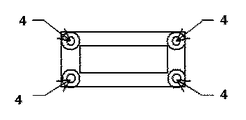
以下、本発明の好適な実施の形態を説明する。図1は本発明で使用する光学ユニットを説明する概略説明図であり、図2は光学ユニットの底面概略図である。図3は本発明の計測装置全体の概略説明図である。 Hereinafter, preferred embodiments of the present invention will be described. FIG. 1 is a schematic explanatory view illustrating an optical unit used in the present invention, and FIG. 2 is a schematic bottom view of the optical unit. FIG. 3 is a schematic explanatory diagram of the whole measuring apparatus of the present invention.
図1において光学ユニット3は、内部に、計測対象物8である塗装面に光を照射する発光素子1及び該塗装面からの反射光を受光する受光素子2が固定設置され、外部は遮光カバーからなり、その一部分に計測対象物8に対して光を照射しその反射光を受光するための開口部を備え、その周りにボールベアリングころ4を配し、計測対象物8に対してボールベアリングころ4を介して接している。
In FIG. 1, an
本発明では、上記光学ユニットを用いて計測対象物8である塗装面に光を照射し、正反射光が入射しない角度から受光した反射光強度を連続的に測定する。
In the present invention, the optical surface is used to irradiate the painted surface, which is the
一般に、物体に光が照射されると、物体の光吸収能に応じて光の一部は該物体に吸収され、「正反射光」と「拡散反射光」として反射される。本明細書及び請求項において「正反射光」とは、計測対象物表面と入射光との接点の法線に対して入射光角度と同じ角度で且つ該入射光と反対の方向に該接点から反射していく光であり、本発明で測定する反射光強度は、拡散反射光の強度であり、拡散反射光とは、計測対象物表面で四方に散乱する光を意味する。発光素子から発せられる光が、平行光である場合は、その光軸の角度から正反射光の角度が決まる。発光素子から発せられる光が、ある程度広がりをもった拡散光である場合は、正反射光は照射光の拡散角度に応じた拡散角度を有する。この場合は、受光素子が拡散した正反射光の一部を受ける可能性がある。但し、拡散角度をもった正反射光の内、周辺部分の正反射光の強度が、計測対象物からの拡散反射光に比して低く、測定上問題とならない場合は、受光素子がそのような正反射光を受けることは、本発明において許容され得る。本発明における「正反射光が入射しない角度」とは、このような角度を含む。 In general, when an object is irradiated with light, a part of the light is absorbed by the object according to the light absorbing ability of the object and reflected as “regular reflection light” and “diffuse reflection light”. In this specification and claims, “regularly reflected light” means the same angle as the incident light angle with respect to the normal of the contact point between the surface of the measurement object and the incident light, and from the contact point in the opposite direction to the incident light. The reflected light intensity measured by the present invention is the intensity of diffuse reflected light, and the diffuse reflected light means light scattered in all directions on the surface of the measurement object. When the light emitted from the light emitting element is parallel light, the angle of the regular reflection light is determined from the angle of the optical axis. When the light emitted from the light emitting element is diffused light having a certain extent, the regular reflected light has a diffusion angle corresponding to the diffusion angle of the irradiation light. In this case, there is a possibility that a part of the regular reflection light diffused by the light receiving element is received. However, if the intensity of the specular reflected light in the peripheral part of the specular reflected light having a diffusion angle is lower than that of the diffuse reflected light from the measurement object and does not cause a problem in measurement, the light receiving element is Receiving regular specularly reflected light is acceptable in the present invention. In the present invention, “an angle at which regular reflection light does not enter” includes such an angle.
前記発光素子1及び受光素子2は、計測対象物8からの拡散反射光の一部が受光素子に受光されるように夫々配置されるように、その好ましい位置関係として、発光素子は、上記開口部の面の中心法線を基準として35〜55°の範囲内の角度となるように設定されることが望ましい。ここで、面の中心法線とは、照射される面の中心を通る法線を意味し、法線を0°として発光素子側の斜角を正の角度とする。受光素子は、開口部の面の中心法線に対して−45〜25°の範囲内の角度となるように設定することができる。
The
上記開口部は、測定時に計測対象物表面に光を照射させ、該計測対象物からの反射光を受光させるために設けられるものであり、その形状としては、円状、方状等特に制限はないが、対称な形状であることが望ましい。 The opening is provided to irradiate light on the surface of the measurement object during measurement and to receive reflected light from the measurement object. The shape of the opening is not particularly limited, such as a circle or a square. It is not desirable, but it is desirable to have a symmetrical shape.
ボールベアリングころ4は、自在に回転可能な球体が計測対象物上に接触可能な構造であれば特に制限なく任意の形状を有するものであり、各ボールベアリングころ4は図2に示すように、上記開口部の周りに配されるものであり、曲面を有する計測対象物上を光学ユニット3が掃引される場合においても、計測対象物面における測定点の法線方向に対する光学ユニット内の発光素子及び受光素子の位置が常に設定された角度を保てるように設置されている。その目的から該ボールベアリングころは3つ又は4つ配されることが望ましく、特に図2のように4つが望ましい。ボールベアリングころを5つ以上設置すると曲率半径の小さい計測対象物の形状に追随した計測が困難になり、ボールベアリングころが2つ以下の場合は発光素子1及び受光素子2が計測対象物に対して不安定な位置関係になり正確な計測ができなくなるので望ましくない。
The ball bearing
各ボールベアリングころ4の配置は、光学ユニット3の掃引計測中に発光素子1及び受光素子2が安定に一定の位置関係を保つために、ボールベアリングころの頂点が幾何学的に線対称な形状に設置されることが望ましく、図2に示すようにボールベアリングころ4を長方形状の四隅に設置することができる。
The arrangement of the
上記光学ユニット3は、図1に示すように、可動関節部6、7及び保持アーム5を介して掃引駆動ロボット(図示せず)に接続されている。保持アーム5は、可動関節部6、7によって、4つのボールベアリングころ4が前記塗装面に接触するように前記光学ユニットを保持している。この構造により、曲面を有する計測対象物8に対しても発光素子1と受光素子2が一定の位置関係を維持し、さらには曲面を有する計測対象物面上を掃引した場合においても、可動関節部6及び7によって発光素子1と受光素子2が計測対象物と一定の距離を維持することができる。
As shown in FIG. 1, the
図3において光学ユニット3は、多関節保持アーム10を介して、単軸ロボットX11及び単軸ロボットY12からなる2軸ロボットに保持されている。多関節保持アーム10は、前記図1に示すような保持アーム5及び可動関節部6及び7によって構成され、多関節保持アーム10の一端は単軸ロボットX11へ固定接続され、他端は光学ユニット3を固定接続している。直交に配置された単軸ロボットX11及び単軸ロボットY12は、ステッピングモーターやサーボモーターなどを使用したアクチュエーターを使用することができ、これらは各々または単一のロボット駆動制御装置13によって制御される。
In FIG. 3, the
本発明方法では、上記2軸ロボットの駆動によって、光学ユニット3を一定速度で計測対象物8である塗装面上に対して略水平方向に往復移動させながら矩形に掃引して、計測対象範囲全体の塗装ムラの程度を2次元的に計測することができる。
In the method of the present invention, by driving the biaxial robot, the
上記光学ユニット3内部に設置された受光素子2の電気信号は、A/D変換機14によって適宜デジタルデータに変換されコンピュータ15へ送信される。また光学ユニット3で計測されA/D変換機14から得られるデジタルデータと計測対象物8面上の正確な位置を同時に得るために、ロボット駆動制御装置13はコンピュータ15と接続している。
The electrical signal of the
上記コンピュータ15では、得られたデジタルデータから、例えば2次元マッピング処理、標準偏差演算処理及びフーリエ変換演算処理を行なうことができる。コンピュータ15で行われる上記処理結果を出力するために、必要に応じて印刷機などを接続することも可能である。
The
本発明では上記の通り得られる2次元マッピングしてなる画像から、計測対象面全体の塗装ムラを評価することができる。また標準偏差や2次元パワースペクトルを用いて、計測対象面の塗装ムラを定量的に評価することができる。 In the present invention, the coating unevenness of the entire measurement target surface can be evaluated from the image obtained by two-dimensional mapping obtained as described above. Moreover, the coating unevenness of the measurement target surface can be quantitatively evaluated using the standard deviation and the two-dimensional power spectrum.
以下、実施例を挙げて本発明方法をさらに詳細に説明する。 Hereinafter, the method of the present invention will be described in more detail with reference to examples.
(測定対象物の作成)
測定対象物は、厚さ0.8mmの湾曲鋼板に、自動車車体塗装と同様に電着塗装及び焼付を行った後、ポリエステル/メラミン硬化系中塗り塗料を塗装及び焼き付けし、メタリック塗装用下地を用意した。次いでメタリック塗装においては、アルミニウムフレークを配合した関西ペイント株式会社製水性ベースコート塗料を用いて、下記表1に記載の条件にて同一塗料を塗装し実施例1〜3の計測対象物を作成した。
(Create measurement object)
The object to be measured is electrodeposited and baked on a curved steel plate with a thickness of 0.8 mm, in the same way as for automobile body painting, and then coated and baked with a polyester / melamine-curing intermediate coating to form a base for metallic coating. Prepared. Next, in metallic coating, the same paint was applied under the conditions described in Table 1 below using water-based base coat paint manufactured by Kansai Paint Co., Ltd., in which aluminum flakes were blended, and measurement objects of Examples 1 to 3 were created.
(計測対象物の計測)
図3と同様の装置を用いて実施例1〜3の計測を行った。駆動及び計測条件は下記表2に記載の条件で行った。尚、発光素子及び受光素子の位置関係は、45°入射/35°受光となるよう設定した。
(Measurement of measurement object)
Measurements in Examples 1 to 3 were performed using the same apparatus as in FIG. Driving and measurement conditions were performed under the conditions described in Table 2 below. The positional relationship between the light emitting element and the light receiving element was set to be 45 ° incident / 35 ° light received.
(計測データの評価と解析)
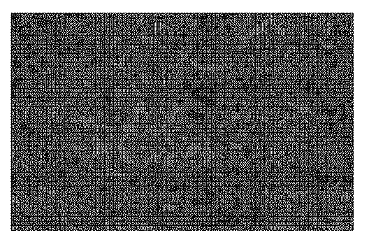
各実施例について計測で得られた78×25点のデータを8階調で2次元マッピングした処理画像を図4、5及び6に示す。2次元マッピング画像上において、濃淡の差が少ないほど塗装ムラ(メタリックムラ)が少ないことを示しており、技術者の目視評価熟練度にかかわり無く計測評価物の塗装ムラ(メタリックムラ)の優劣を認識し決定することができる。具体的には実施例1(図4)が塗装ムラが少なく、実施例2(図5)がムラなく優れており、実施例3(図6)は顕著な塗装ムラが生じていることがわかる。本実施例では、マイクロソフト社製表計算ソフト「エクセル」を使用して、2次元マッピングを作成したが、2次元的な数値データを図示可能なソフトウェアであれば、適宜選択して使用することができる。
(Evaluation and analysis of measurement data)
4, 5 and 6 show processed images obtained by two-dimensionally mapping 78 × 25 points of data obtained by measurement for each example with 8 gradations. On the two-dimensional mapping image, the smaller the difference in shading, the less the coating unevenness (metallic unevenness), and the superiority or inferiority of the coating unevenness (metallic unevenness) of the measurement evaluation object regardless of the level of skill of the visual evaluation of the engineer. Can be recognized and determined. Specifically, Example 1 (FIG. 4) has little coating unevenness, Example 2 (FIG. 5) is excellent with no unevenness, and Example 3 (FIG. 6) shows remarkable coating unevenness. . In this embodiment, the two-dimensional mapping is created using Microsoft spreadsheet software “Excel”. However, any software that can display two-dimensional numerical data can be selected and used as appropriate. it can.
さらに計測によって得られたデータは、フーリエ変換による解析によって定量的な評価を導き出すことができる。各実施例について2次元フーリエ変換を行って得られる2次元パワースペクトルの処理画像を図7、8及び9に示した。2次元フーリエ変換には、計測データのうち50×50の正方データを使用して行い、特に顕著な差異が認められる低周波数(1〜10Hz)のデータにおいて、スペクトルデータの値が大きいものほど明度が小さくなるよう図示した。表3に示したように、2次元パワースペクトルデータの最大値は計測データの2次元マッピングから得られた定性的な官能評価と逆相関を示しており、パワースペクトルデータの最大値によって塗装ムラの程度を定量的に評価できることがわかる。 Furthermore, quantitative evaluation of the data obtained by measurement can be derived by analysis by Fourier transform. The processed images of the two-dimensional power spectrum obtained by performing the two-dimensional Fourier transform for each example are shown in FIGS. The two-dimensional Fourier transform is performed using 50 × 50 square data among the measurement data. In particular, in the low frequency data (1 to 10 Hz) in which a remarkable difference is recognized, the higher the value of the spectrum data, the lighter the brightness. Is shown to be smaller. As shown in Table 3, the maximum value of the two-dimensional power spectrum data shows a negative correlation with the qualitative sensory evaluation obtained from the two-dimensional mapping of the measurement data. It can be seen that the degree can be quantitatively evaluated.
1 発光素子
2 受光素子
3 光学ユニット
4 ボールベアリングころ
5 保持アーム
6、7 可動関節部
8 計測対象物
10 多関節保持アーム
11 単軸ロボットX
12 単軸ロボットY
13 ロボット駆動制御装置
14 A/D変換機
15 コンピュータ
DESCRIPTION OF
12 Single-axis robot Y
13 Robot Drive Control Device 14 A /
Claims (6)
前記塗装面に光を照射する発光素子及び該塗装面からの反射光を受光する受光素子を内蔵し、3つ又は4つのボールベアリングころによって支持された光学ユニットと、
該光学ユニットに具備された全てのボールベアリングころが前記塗装面に接触するように前記光学ユニットを保持可能で且つ前記塗装面上を移動可能とせしめるロボットと、
該ロボットの制御装置と、
前記光学ユニットによって測定された反射光強度を処理可能な処理装置とを具備する塗装ムラの計測装置。 A device that irradiates light on a metallic coating surface and continuously measures reflected light intensity received from an angle at which regular reflection light does not enter to measure coating unevenness on the coating surface,
A light-emitting element that irradiates light on the painted surface and a light-receiving element that receives reflected light from the painted surface, and an optical unit supported by three or four ball bearing rollers;
A robot capable of holding the optical unit and moving on the painted surface so that all ball bearing rollers provided in the optical unit are in contact with the painted surface;
A control device for the robot;
A coating unevenness measuring device comprising: a processing device capable of processing the reflected light intensity measured by the optical unit.
該光学ユニットが、3つ又は4つのボールベアリングころを介して前記塗装面上に接触し且つ移動可能であり、
該光学ユニットを一定速度で前記塗装面上に対して略水平方向に往復移動させながら矩形に掃引して、計測対象面全体の塗装ムラの程度を2次元的に計測することを特徴とする塗装ムラの計測方法。 A method of measuring coating unevenness on a painted surface using an optical unit that continuously irradiates light on a metallic painted surface and continuously measures the intensity of reflected light received from an angle at which regular reflected light is not incident.
The optical unit is in contact with and movable on the painted surface via three or four ball bearing rollers;
The coating is characterized in that the optical unit is swept into a rectangle while reciprocating in a substantially horizontal direction with respect to the coating surface at a constant speed, and the degree of coating unevenness on the entire surface to be measured is measured two-dimensionally. Measurement method of unevenness.
Coating unevenness obtained by quantitatively evaluating the coating unevenness of the measurement target surface using a two-dimensional power spectrum obtained by performing two-dimensional Fourier transform on the reflected light intensity data measured by the method according to claim 3. Evaluation method.
Priority Applications (1)
| Application Number | Priority Date | Filing Date | Title |
|---|---|---|---|
| JP2005013486A JP2006201045A (en) | 2005-01-21 | 2005-01-21 | Uneven painting measuring instrument, measuring method, and evaluation method |
Applications Claiming Priority (1)
| Application Number | Priority Date | Filing Date | Title |
|---|---|---|---|
| JP2005013486A JP2006201045A (en) | 2005-01-21 | 2005-01-21 | Uneven painting measuring instrument, measuring method, and evaluation method |
Publications (1)
| Publication Number | Publication Date |
|---|---|
| JP2006201045A true JP2006201045A (en) | 2006-08-03 |
Family
ID=36959174
Family Applications (1)
| Application Number | Title | Priority Date | Filing Date |
|---|---|---|---|
| JP2005013486A Pending JP2006201045A (en) | 2005-01-21 | 2005-01-21 | Uneven painting measuring instrument, measuring method, and evaluation method |
Country Status (1)
| Country | Link |
|---|---|
| JP (1) | JP2006201045A (en) |
Cited By (1)
| Publication number | Priority date | Publication date | Assignee | Title |
|---|---|---|---|---|
| CN121650350A (en) * | 2026-02-06 | 2026-03-13 | 婴舒宝(中国)有限公司 | Online high-speed sanitary towel spraying decoration system and method |
Citations (9)
| Publication number | Priority date | Publication date | Assignee | Title |
|---|---|---|---|---|
| JPS582607U (en) * | 1981-06-30 | 1983-01-08 | トヨタ自動車株式会社 | Simple unevenness measuring device |
| JPS6441847A (en) * | 1987-08-07 | 1989-02-14 | Kurashiki Boseki Kk | Surface defect detection system for metallic product |
| JPH05288690A (en) * | 1992-04-10 | 1993-11-02 | Kansai Paint Co Ltd | Method for determining painting nonuniformitty of metalic paint film |
| JPH09318448A (en) * | 1996-05-27 | 1997-12-12 | Nissan Motor Co Ltd | Color unevenness determination device and evaluation method for metallic coating |
| JP2000065750A (en) * | 1998-06-10 | 2000-03-03 | Kansai Paint Co Ltd | Method for quantitatively evaluating brilliant feeling of coating film |
| JP2001205327A (en) * | 2000-01-28 | 2001-07-31 | Sumitomo Metal Ind Ltd | Surface property determination device |
| JP2002372498A (en) * | 2001-06-13 | 2002-12-26 | Kanto Auto Works Ltd | Coated surface inspection apparatus for vehicle |
| JP2003065964A (en) * | 2001-08-28 | 2003-03-05 | Daihatsu Motor Co Ltd | Coating-irregularity inspecting method |
| JP2004354381A (en) * | 2003-05-27 | 2004-12-16 | Byk Gardner Gmbh | Apparatus and method for specifying surface properties |
-
2005
- 2005-01-21 JP JP2005013486A patent/JP2006201045A/en active Pending
Patent Citations (9)
| Publication number | Priority date | Publication date | Assignee | Title |
|---|---|---|---|---|
| JPS582607U (en) * | 1981-06-30 | 1983-01-08 | トヨタ自動車株式会社 | Simple unevenness measuring device |
| JPS6441847A (en) * | 1987-08-07 | 1989-02-14 | Kurashiki Boseki Kk | Surface defect detection system for metallic product |
| JPH05288690A (en) * | 1992-04-10 | 1993-11-02 | Kansai Paint Co Ltd | Method for determining painting nonuniformitty of metalic paint film |
| JPH09318448A (en) * | 1996-05-27 | 1997-12-12 | Nissan Motor Co Ltd | Color unevenness determination device and evaluation method for metallic coating |
| JP2000065750A (en) * | 1998-06-10 | 2000-03-03 | Kansai Paint Co Ltd | Method for quantitatively evaluating brilliant feeling of coating film |
| JP2001205327A (en) * | 2000-01-28 | 2001-07-31 | Sumitomo Metal Ind Ltd | Surface property determination device |
| JP2002372498A (en) * | 2001-06-13 | 2002-12-26 | Kanto Auto Works Ltd | Coated surface inspection apparatus for vehicle |
| JP2003065964A (en) * | 2001-08-28 | 2003-03-05 | Daihatsu Motor Co Ltd | Coating-irregularity inspecting method |
| JP2004354381A (en) * | 2003-05-27 | 2004-12-16 | Byk Gardner Gmbh | Apparatus and method for specifying surface properties |
Cited By (2)
| Publication number | Priority date | Publication date | Assignee | Title |
|---|---|---|---|---|
| CN121650350A (en) * | 2026-02-06 | 2026-03-13 | 婴舒宝(中国)有限公司 | Online high-speed sanitary towel spraying decoration system and method |
| CN121650350B (en) * | 2026-02-06 | 2026-04-17 | 婴舒宝(中国)有限公司 | Online high-speed sanitary towel spraying decoration system and method |
Similar Documents
| Publication | Publication Date | Title |
|---|---|---|
| JP7648723B2 (en) | Three-dimensional surface roughness evaluation method and three-dimensional surface roughness evaluation device | |
| CN111085837B (en) | Automatic assembly position attitude measurement method | |
| US11402353B2 (en) | Imaging beam adjustments on a non-destructive inspection sensor situated on a robotic effector to accommodate in situ conditions | |
| CN110044293B (en) | Three-dimensional reconstruction system and three-dimensional reconstruction method | |
| US7813470B2 (en) | Three-dimensional contents determination method using transmitted x-ray | |
| CN112964184B (en) | Oil film thickness measuring device and measuring method based on surface friction resistance experiment | |
| CN109906354A (en) | Uniformity test artifact for coordinate measuring machine | |
| Pei et al. | A quantitative comparison of in-line coating thickness distributions obtained from a pharmaceutical tablet mixing process using discrete element method and terahertz pulsed imaging | |
| CN114322842B (en) | A method and system for measuring highly reflective parts based on the improved Phong model | |
| CN110375901B (en) | X-ray stress measuring instrument and method for complex surface and storage medium | |
| US20220113259A1 (en) | Method and system for inspecting repair or assembly operations | |
| IT201800005143A1 (en) | Method for checking an object made of transparent material and related control system | |
| CN106289060A (en) | A kind of system and method measuring planar LED fluorescent coating volume | |
| Pan et al. | Method of using non-specific target to complete structured light plane calibration | |
| US20110085582A1 (en) | Method for studying the surface composition of planar structures | |
| CN117095065B (en) | Line spectrum confocal displacement sensor calibration method, system and equipment | |
| Moller et al. | An automatic evaluation procedure for 3-D scanners in robotics applications | |
| JP2006201045A (en) | Uneven painting measuring instrument, measuring method, and evaluation method | |
| EP1610089A3 (en) | Method and device for measuring the angle of optical surfaces | |
| RU2419069C2 (en) | Method for noncontact measurement of shape of object | |
| US11948293B2 (en) | Method and arrangement for determining a position of an object | |
| WO2014038601A1 (en) | Device for measuring distribution of coating film surface roughness | |
| JPWO2022269300A5 (en) | ||
| JP2012088265A (en) | Method and device for measuring glossiness | |
| CN117213401B (en) | Surface industry visual detection method and system based on structured light tangential scanning |
Legal Events
| Date | Code | Title | Description |
|---|---|---|---|
| A621 | Written request for application examination |
Effective date: 20071211 Free format text: JAPANESE INTERMEDIATE CODE: A621 |
|
| A131 | Notification of reasons for refusal |
Effective date: 20100601 Free format text: JAPANESE INTERMEDIATE CODE: A131 |
|
| A977 | Report on retrieval |
Free format text: JAPANESE INTERMEDIATE CODE: A971007 Effective date: 20100603 |
|
| A02 | Decision of refusal |
Free format text: JAPANESE INTERMEDIATE CODE: A02 Effective date: 20101019 |