JP2006201225A - projector - Google Patents
projector Download PDFInfo
- Publication number
- JP2006201225A JP2006201225A JP2005009974A JP2005009974A JP2006201225A JP 2006201225 A JP2006201225 A JP 2006201225A JP 2005009974 A JP2005009974 A JP 2005009974A JP 2005009974 A JP2005009974 A JP 2005009974A JP 2006201225 A JP2006201225 A JP 2006201225A
- Authority
- JP
- Japan
- Prior art keywords
- light
- case member
- projector
- speaker
- optical system
- Prior art date
- Legal status (The legal status is an assumption and is not a legal conclusion. Google has not performed a legal analysis and makes no representation as to the accuracy of the status listed.)
- Withdrawn
Links
- 230000003287 optical effect Effects 0.000 claims abstract description 73
- 238000005286 illumination Methods 0.000 claims description 36
- 230000000694 effects Effects 0.000 claims description 8
- 238000005192 partition Methods 0.000 claims description 6
- 238000003384 imaging method Methods 0.000 claims description 4
- 230000015572 biosynthetic process Effects 0.000 claims description 3
- 238000009423 ventilation Methods 0.000 abstract description 8
- 238000005728 strengthening Methods 0.000 abstract description 2
- 239000004973 liquid crystal related substance Substances 0.000 description 30
- 230000010287 polarization Effects 0.000 description 14
- 238000006243 chemical reaction Methods 0.000 description 8
- 238000001816 cooling Methods 0.000 description 8
- 238000009413 insulation Methods 0.000 description 8
- 239000003086 colorant Substances 0.000 description 6
- 239000000853 adhesive Substances 0.000 description 2
- 230000001070 adhesive effect Effects 0.000 description 2
- NJPPVKZQTLUDBO-UHFFFAOYSA-N novaluron Chemical compound C1=C(Cl)C(OC(F)(F)C(OC(F)(F)F)F)=CC=C1NC(=O)NC(=O)C1=C(F)C=CC=C1F NJPPVKZQTLUDBO-UHFFFAOYSA-N 0.000 description 2
- 230000005540 biological transmission Effects 0.000 description 1
- 238000007664 blowing Methods 0.000 description 1
- 238000010586 diagram Methods 0.000 description 1
- 239000011159 matrix material Substances 0.000 description 1
- QSHDDOUJBYECFT-UHFFFAOYSA-N mercury Chemical compound [Hg] QSHDDOUJBYECFT-UHFFFAOYSA-N 0.000 description 1
- 229910052753 mercury Inorganic materials 0.000 description 1
- 238000012544 monitoring process Methods 0.000 description 1
- 238000000926 separation method Methods 0.000 description 1
- 239000002847 sound insulator Substances 0.000 description 1
- 230000009466 transformation Effects 0.000 description 1
Images

Abstract
【課題】 スピーカキャビネットを設けたり、通風用ダクトを長くすることなく、スピーカ音声の低音を強くして音質を厚くすることができるプロジェクタを提供すること。
【解決手段】 このプロジェクタ10では、本体光学装置11のケース部材11a内の一部に形成される収納室C1がスピーカ17のためのスピーカキャビネットとなっているので、スピーカ音声の低音を強くすることができ、音質を厚くすることができる。つまり、プロジェクタ10中の音源をホームシアター等の用途に適合する程度の高度の音質とすることができる。この際、本体光学装置11のケース部材11aをスピーカキャビネットとして流用するので、プロジェクタ10を小型にすることができ、持ち運び性や省スペース性といった特徴を発揮させることができる。
【選択図】 図1
PROBLEM TO BE SOLVED: To provide a projector capable of increasing sound quality by strengthening low sound of speaker sound without providing a speaker cabinet or lengthening a ventilation duct.
In this projector, since a storage chamber C1 formed in a part of a case member 11a of a main body optical device 11 serves as a speaker cabinet for a speaker 17, the bass sound of the speaker sound is strengthened. Can increase the sound quality. In other words, the sound source in the projector 10 can have a high sound quality that is suitable for a home theater or the like. At this time, since the case member 11a of the main body optical device 11 is used as a speaker cabinet, the projector 10 can be reduced in size, and features such as portability and space saving can be exhibited.
[Selection] Figure 1
Description
本発明は、液晶パネル等の光変調装置を用いて画像を投射するプロジェクタに関する。 The present invention relates to a projector that projects an image using a light modulation device such as a liquid crystal panel.
最近のプロジェクタとして、持ち運び性や省スペースを実現した小型のプロジェクタが開発されており、このような小型プロジェクタでは、光学経路等を含む他の構成部品の妨げにならないように、スピーカキャビネットを持たない平面バッフル型のスピーカが通常用いられている。 As a recent projector, a small projector that realizes portability and space saving has been developed, and such a small projector does not have a speaker cabinet so as not to interfere with other components including an optical path. A flat baffle type speaker is usually used.
別のプロジェクタとして、冷却ファンを設けた通風用ダクトの経路上に消音用スピーカを配置し、その経路上の下流側にサブウーハー用スピーカを設けたものが存在する。このプロジェクタでは、通風用ダクトの一部をサブウーハー用スピーカのスピーカダクトとして利用する(例えば特許文献1参照)。
しかし、平面バッフル型のスピーカの場合、スピーカキャビネットを設けないと、低音が弱くなり音質が薄くなる傾向がある。なお、スピーカキャビネットを設けた場合、その分だけ、プロジェクタの本体サイズが増加することになる。 However, in the case of a flat baffle type speaker, if a speaker cabinet is not provided, the low tone tends to be weak and the sound quality tends to be thin. When the speaker cabinet is provided, the projector main body size increases accordingly.
また、通風用ダクトの一部をスピーカダクトとして利用する場合、通風用ダクトがある程度長いことが前提となる。つまり、省スペースとなるように通風用ダクトを最も短く設計した場合、かかる通風用ダクトの出口側に消音用スピーカを設けるのやっとである。 Further, when a part of the ventilation duct is used as a speaker duct, it is assumed that the ventilation duct is somewhat long. That is, when the ventilation duct is designed to be the shortest so as to save space, it is only possible to provide a muffler speaker on the outlet side of the ventilation duct.
そこで、本発明は、専用のスピーカキャビネットを設けたり、通風用ダクトを長くすることなく、スピーカ音声の低音を強くして音質を厚くすることができるプロジェクタを提供することを目的とする。 Therefore, an object of the present invention is to provide a projector capable of increasing the sound quality by strengthening the bass sound of a speaker without providing a dedicated speaker cabinet or lengthening a ventilation duct.
上記課題を解決するため、本発明に係るプロジェクタは、(a)画像形成及び画像投射用の映像光学系と、(b)映像光学系の少なくとも一部を周囲から遮光するケース部材と、(c)ケース部材内部に連通して当該ケース部材による音響効果を利用するスピーカとを備える。 In order to solve the above problems, a projector according to the present invention includes (a) an image optical system for image formation and image projection, (b) a case member that shields at least a part of the image optical system from the surroundings, And a speaker that communicates with the inside of the case member and uses the acoustic effect of the case member.
上記プロジェクタでは、スピーカが、ケース部材による音響効果を生じさせるように、当該ケース部材に固定されて当該ケース部材内部に連通するので、特別にスピーカキャビネットを設けることなく、映像光学系用のケース部材内部の空洞を流用して、スピーカ音声の低音を強くすることができ、音質を厚くすることができる。 In the projector, since the speaker is fixed to the case member and communicates with the inside of the case member so as to generate the acoustic effect by the case member, the case member for the imaging optical system is not provided with a special speaker cabinet. By utilizing the internal cavity, it is possible to strengthen the bass sound of the speaker and increase the sound quality.
また、本発明の具体的側面又は態様では、上記プロジェクタにおいて、ケース部材が、映像光学系の少なくとも一部を構成する光学部品を支持する支持部材を内蔵する。この場合、ケース部材の形状の自由度を高めることができ、ケース部材内の空洞容積を有効に活用することができる。 In a specific aspect or aspect of the present invention, in the projector, the case member includes a support member that supports an optical component that constitutes at least a part of the imaging optical system. In this case, the freedom degree of the shape of a case member can be raised and the cavity volume in a case member can be utilized effectively.
また、本発明の別の具体的態様では、支持部材が枠状の構造体である。この場合、支持部材が音の遮蔽体となる可能性を低減でき、ケース部材による音響効果を高めることができる。 In another specific aspect of the present invention, the support member is a frame-like structure. In this case, the possibility that the support member becomes a sound shield can be reduced, and the acoustic effect of the case member can be enhanced.
また、本発明の別の具体的態様では、ケース部材が当該記ケース部材内部の空洞形状を調節する仕切部材を備える。この場合、空洞形状の調節によって、ケース部材による音響効果を目標とする状態に設定することができる。 Moreover, in another specific aspect of the present invention, the case member includes a partition member that adjusts the hollow shape inside the case member. In this case, the acoustic effect by the case member can be set to a target state by adjusting the cavity shape.
また、本発明の別の具体的態様では、仕切部材が、映像光学系の光路上に配置される均一で透明な部材である。この場合、光路を横切る遮音体によって音響効果を調整することができ、空洞形状の自由度をさらに高めることができる。 In another specific aspect of the present invention, the partition member is a uniform and transparent member disposed on the optical path of the imaging optical system. In this case, the acoustic effect can be adjusted by the sound insulator crossing the optical path, and the degree of freedom of the cavity shape can be further increased.
また、本発明の別の具体的態様では、映像光学系が、照明光を射出する照明装置と、照明光によって照明される光変調装置と、光変調装置を経て形成された像光を投射する投射光学系とを備え、スピーカが、ケース部材のうち照明装置の少なくとも一部を収納する壁体部分に取り付けられる。この場合、照明装置側の光学要素は、音響振動によって画質に直結する影響を受けにくいので、投射画像の画質を高品位に保ちつつ、スピーカの音質を高めることができる。 In another specific aspect of the present invention, the image optical system projects an illumination device that emits illumination light, a light modulation device that is illuminated by the illumination light, and image light formed through the light modulation device. A projection optical system is provided, and a speaker is attached to a wall portion that houses at least a part of the illumination device in the case member. In this case, the optical element on the illuminating device side is not easily affected by the sound vibration, and thus the sound quality of the speaker can be improved while maintaining the image quality of the projected image at a high quality.
図1は、本発明の一実施形態に係るプロジェクタを説明する図である。このプロジェクタ10は、光学エンジンユニットとも呼ばれる本体光学装置11と、ランプ光源等に電力を供給する電源装置14と、ランプ光源等を空冷するための冷却ファンユニット15と、装置全体の動作を制御する回路基板16と、音声出力用のスピーカ17と、全体を覆う外装ケース19とを備える。
FIG. 1 is a diagram illustrating a projector according to an embodiment of the invention. The
このうち、本体光学装置11は、光源光を発生する光源装置20と、光源装置20からの照明光を均一化する均一化光学系30と、均一化光学系30を経た照明光を赤・緑・青の3色に分割する分割照明系40と、分割照明系40から射出された各色の照明光によって照明される光変調部50と、光変調部50からの各色の変調光を合成するクロスダイクロイックプリズム60と、クロスダイクロイックプリズム60を経た像光をスクリーン(不図示)に投射する投射レンズ70とを備える。これらの光源装置20、均一化光学系30、分割照明系40、光変調部50、クロスダイクロイックプリズム60、及び投射レンズ70は、映像光学系を構成し、L字状に折れ曲がった外観を有し遮光性を有するケース部材11a中に略全体が収納されている。このケース部材11aの存在により、本体光学装置11内部が周囲から遮光され、かつ、本体光学装置11から周囲への漏光が防止される。なお、以上の構成要素うち、光源装置20、均一化光学系30、及び分割照明系40は、各色の照明光を射出する照明装置として機能する。
Among these, the main body
ここで、光源装置20は、略点状の発光部を形成するランプ本体21と、ランプ本体21から射出される光源光をコリメートするべくパラボラその他の形状を有する凹面鏡22とを備える。このうち、ランプ本体21は、例えば高圧水銀ランプ等のランプ光源からなり、略白色の光源光を発生する。また、凹面鏡22は、ランプ本体21から放射される光線を反射して、略平行光束として均一化光学系30に入射させる。
Here, the
均一化光学系30は、一対のフライアイ光学系31,32と、波面分割光を重ね合わせるための重畳レンズ33と、照明光を所定の偏光成分に変換する偏光変換部材34とを備える。一対のフライアイ光学系31,32は、マトリックス状に配置された複数の要素レンズからなり、これらの要素レンズによって、光源装置20からの照明光を分割して個別に集光・発散させる。偏光変換部材34は、フライアイ光学系31,32から射出した照明光を一種類の偏光光に変換して次段光学系に供給する。重畳レンズ33は、偏光変換部材34を経た照明光を全体として適宜収束させて、光変調部50に設けた各色の光変調装置に対する重畳照明を可能にする。つまり、両フライアイ光学系31,32と重畳レンズ33とを経た照明光は、以下に詳述する分割照明系40を経て、光変調部50を構成する各色の光変調装置、すなわち各色の液晶パネル51r,51b,51gの画像形成領域を均一に重畳照明する。
The homogenizing
分割照明系40は、色分離光学系であり、第1及び第2ダイクロイックミラー41a,41bと、反射ミラー42a,42b,42cとを備える。この分割照明系40は、均一化光学系30を経た照明光を赤色光、青色光、及び緑色光の3つの光束に分離する。すなわち、第1ダイクロイックミラー41aは、赤・青・緑(R・G・B)の3色のうち赤色光LRを反射し、青色光LBと緑色光LGとを透過させる。また、第2ダイクロイックミラー41bは、入射した青色光LB及び緑色光LGのうち青色光LBを反射し緑色光LGを透過させる。なお、図示を省略しているが、緑色光LGの光路上の反射ミラー42b,42cの周辺には、緑色と他の色との光路差を補償するためのリレーレンズが配置されている。また、分割照明系40の出力部、すなわち3つのミラー42a,41b,42cの射出側には、各色の液晶パネル51r,51b,51gに対向してフィールドレンズが配置されている。
The divided
光変調部50は、3色の照明光LR,LB,LGがそれぞれ入射する3つの液晶パネル(液晶表示パネル)51r,51b,51gを備える。なお、図示を省略しているが、各液晶パネル51r,51b,51gを挟むように3組の偏光フィルタが配置されている。各液晶パネル51r,51b,51gとこれらを挟む一対の偏光フィルタとは、各色用の液晶ライトバルブを構成する。
The
この光変調部50において、反射ミラー42aで反射された赤色光LRは、液晶パネル51rの画像形成領域に入射し、ダイクロイックミラー41bで反射された青色光LBは、液晶パネル51bの画像形成領域に入射し、ダイクロイックミラー41bで反射された緑色光LGは、液晶パネル51gの画像形成領域に入射する。各液晶パネル51r,51b,51gは、不図示の偏光フィルタとともに、入射した照明光の偏光方向の空間的分布を変化させるための非発光で透過型の光変調装置として機能し、各液晶パネル51r,51b,51gにそれぞれ入射した各色光LR,LB,LGは、各液晶パネル51r,51b,51gに電気的信号として入力された駆動信号或いは制御信号に応じて、画素単位で偏光状態が調整される。
In the
クロスダイクロイックプリズム60は、カラー画像を合成するための光合成光学系であり、その内部には、赤色光反射用の第1ダイクロイック膜(具体的には誘電体多層膜)61と、緑色光反射用の第2ダイクロイック膜(具体的には誘電体多層膜)62とが、X字状に配置されている。このクロスダイクロイックプリズム60は、液晶パネル51rからの赤色光LRを第1ダイクロイック膜61で反射して進行方向左側に射出させ、液晶パネル51bからの青色光LBを両ダイクロイック膜61,62を介して直進・射出させ、液晶パネル51gからの緑色光LGを第2ダイクロイック膜62で反射して進行方向右側に射出させる。
The cross
このようにクロスダイクロイックプリズム60で合成された像光は、投射光学系である投射レンズ70を経て、適当な拡大率でスクリーン(不図示)にカラー画像として投射される。
The image light synthesized by the cross
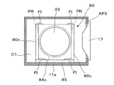
以上説明した本体光学装置11において、ケース部材11aのうち一方の収納室C1の一端に形成された開口AP1は、この開口AP1の周囲の壁体部分に固定された光源装置20によって封止されている。また、収納室C1中には、均一化光学系30が収納されている。一方、ケース部材11aのうち他方の収納室C2の一端に形成された開口AP2には、投射レンズ70が埋め込まれた状態で壁体部分に固定されている。また、収納室C2中には、分割照明系40と、光変調部50と、クロスダイクロイックプリズム60とが収納されている。
In the main body
ケース部材11aの収納室C1側の空洞中には、均一化光学系30を構成する各光学部品を支持するための支持部材80が収納され固定されている。この支持部材80は、フライアイ光学系31,32、重畳レンズ33、及び偏光変換部材34を収納室C1内の適所に支持するためのものであるが、枠状の構造体であることから、各光学部品31,32,33,34によって収納室C1内部が細かく分割されることを防止できる。つまり、ケース部材11a内の収納室C1側の空洞容積を大きくすることができるので、ケース部材11aによる音響効果を高めることができる。
A
ケース部材11a内において、収納室C1と収納室C2との間には、均一化光学系30の光路を避けるように、当該光路の回りに音を反射する遮音板81が取り付けられている。また、遮音板81の開口を塞ぐように音を反射する透明遮音板82が配置されており、支持部材80に支持されている。つまり、収納室C1と収納室C2との間は、仕切部材として機能する遮音板81、透明遮音板82、及び支持部材80によって空間的・音響的に仕切られており、均一化光学系30を収納する収納室C1全体がスピーカ17用のスピーカキャビネットになっている。なお、透明遮音板82は、均一な屈折率を有する平行平板であり、両表面には、反射防止膜が形成されている。これら透明遮音板82等の存在により、収納室C1内の音波を比較的効率よく収納室C1内に閉じ込めることができ、しかも、均一化光学系30による照明光の形成は妨げられないようになっている。
In the
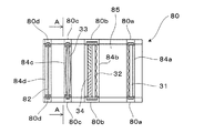
図2は、支持部材80の構造を説明する平面図であり、図3は、支持部材80の配置を説明するAA矢視断面図である。図2からも明らかなように、支持部材80は、矩形の部材であるホルダ84a,84b,84c,84dを両側からそれぞれ支持する支柱部分80a,80b,80c,80dと、これらの支柱部分80a,80b,80c,80dを根元側で支持する板状の台座85とを備える。対向する支柱部分80a,80b,80c,80d間に支持される各ホルダ84a,84b,84c,84dは、フライアイ光学系31と、フライアイ光学系32及び偏光変換部材34と、重畳レンズ33と、透明遮音板82とを、それぞれ光学的にアライメントした状態で保持している。各ホルダ84a,84b,84c,84dは、例えば図3に示すように両脇上部に一対の突起PRを有しており、これらの突起PRは、対向する支柱部分80a,80b,80c,80dの対向する内側面に設けた不図示の溝に、緩みなく嵌り込むようになっている。この際、各ホルダ84a,84b,84c,84dの底部や上部に接着剤からなる固着部FIを形成して、ホルダ84a,84b,84c,84dの固定を確実にしている。また、このようにホルダ84a,84b,84c,84dを接着剤からなる固着部FIによって強固に固定することにより、各光学部品31,32,33,34がスピーカ17からの音波で振動する現象等を抑えることができ、均一化光学系30の光学性能を長期間に亘って安定に保持することができる。
FIG. 2 is a plan view for explaining the structure of the
図1に戻って、電源装置14は、光源装置20に設けたランプ本体21を所望の輝度で点灯させるとともに、冷却ファンユニット15や回路基板16に適当な電力を供給する。なお、冷却ファンユニット15及び回路基板16用に電源装置14とは別の電源を設けることもできる。
Returning to FIG. 1, the
冷却ファンユニット15は、回路基板16からの制御信号を受けて適当な出力で送風動作を行う。これにより、ランプ本体21周辺の空気が循環し或いはランプ本体21周辺に新鮮な外気が供給され、ランプ本体21の空冷が行われる。結果的に、光源装置20の動作を安定化し、その寿命を長くすることができる。
The cooling
回路基板16は、本体光学装置11の上方に主に配置されており、光変調部50の各液晶パネル51r,51b,51gに対し駆動信号等を出力する。また、回路基板16は、光源装置20のアイドリング動作や点灯を制御する。また、回路基板16は、冷却ファンユニット15の稼働状態を監視しつつ制御する。また、回路基板16は、スピーカ17に電力を供給して音声を出力させる。つまり、スピーカ17からは、各液晶パネル51r,51b,51gに出力される駆動信号に対応するビデオ信号の音声が出力される。
The
スピーカ17は、平面バッフル型の小型スピーカであり、本体光学装置11のケース部材11aに設けた開口AP3に一部が嵌め込まれるような状態でケース部材11aの壁体部分に固定されており、ケース部材11aの収納室C1に連通している。この結果、収納室C1がスピーカ17のためのスピーカキャビネットとなって、スピーカ17の音響効果を高めることができる。
The
以下、本実施形態に係るプロジェクタ10の動作について説明する。光源装置20からの照明光は、均一化光学系30を経て偏光方向が揃えられ均一化された後、分割照明系40に設けた第1及び第2ダイクロイックミラー41a,41bによって色分割され、対応する液晶パネル51r,51b,51gに各色光LR,LB,LGとしてそれぞれ入射する。各液晶パネル51r,51b,51gは、外部からのビデオ信号等によって変調されて2次元的屈折率分布を有しており、各色光LR,LB,LGを2次元空間的に画素単位で変調する。このように、各液晶パネル51r,51b,51gで変調された各色光LR,LB,LGすなわち像光は、クロスダイクロイックプリズム60で合成された後、投射レンズ70に入射する。投射レンズ70に入射したカラーの像光は、適当な倍率でスクリーンに投影される。
Hereinafter, the operation of the
以上説明した本実施形態のプロジェクタ10では、本体光学装置11のケース部材11a内に形成される収納室C1がスピーカ17のためのスピーカキャビネットとなっているので、スピーカ音声の低音を強くすることができ、その音質を厚くすることができる。つまり、プロジェクタ10に内蔵された音源を、ホームシアター等の用途に適合する程度の高度の音質とすることができる。この際、本体光学装置11のケース部材11a自体をスピーカキャビネットとして流用するので、プロジェクタ10を小型にすることができ、持ち運び性や省スペース性といった特徴を十分に発揮させることができる。
In the
なお、この発明は、上記の実施形態に限られるものではなく、その要旨を逸脱しない範囲において種々の態様で実施することが可能であり、例えば次のような変形も可能である。 In addition, this invention is not restricted to said embodiment, In the range which does not deviate from the summary, it can be implemented in a various aspect, For example, the following deformation | transformation is also possible.
すなわち、上記実施形態では、ケース部材11aの収納室C1をスピーカキャビネットとしたが、収納室C2をスピーカキャビネットとすることもでき、両収納室C1,C2をスピーカキャビネットとすることもできる。その際、スピーカ17を固定する位置はケース部材11aの側壁が望ましい。上記実施形態では、回路基板16が本体光学装置11の上方に配置されているからである。よって、回路基板16が例えば本体光学装置11の下側に配置される場合、スピーカ17をケース部材11aの上部壁に取り付けることもできる。
That is, in the said embodiment, although the storage room C1 of the
また、上記実施形態では、遮音板81、透明遮音板82、及び支持部材80によって、収納室C1と収納室C2との間を遮空間的に仕切っていたが、その他の遮音部材を収納室C2内の適所に配置することができ、各遮音部材の配置によって所望の音響特性を実現することができる。遮音板81、透明遮音板82等の配置も、図1に例示するものに限らず、要求される音質に応じて適切なものに変更することができる。
In the above embodiment, the
また、上記実施形態では、3色の液晶パネルを合成する場合について説明したが、カラータイプの液晶パネルを直接投影する場合も同様である。すなわち、カラータイプの単板式液晶パネルと、これを照明する照明装置と、単板式液晶パネルの像を投影する投射レンズとを内部に保持するケース部材のどの部分かにスピーカを固定することにより、このケース部材をスピーカキャビネットとして活用することができる。 In the above embodiment, the case where three color liquid crystal panels are combined has been described. However, the same applies to the case where a color type liquid crystal panel is directly projected. That is, by fixing the speaker to any part of the case member that holds the color type single-panel liquid crystal panel, the illumination device that illuminates this, and the projection lens that projects the image of the single-panel liquid crystal panel inside, This case member can be utilized as a speaker cabinet.
また、上記実施形態では、光源装置20からの光を複数の部分光束に分割するため、2つのフライアイ光学系31,32を用いていたが、この発明は、このようなフライアイ光学系すなわちレンズアレイを用いないプロジェクタにも適用可能である。さらに、フライアイ光学系31,32をロッドインテグレータに置き換えることもできる。
In the above embodiment, the two fly's eye
また、上記プロジェクタ10において、光源装置20からの光を特定方向の偏光とする偏光変換部材34を用いていたが、この発明は、このような偏光変換部材34を用いないプロジェクタにも適用可能である。
In the
また、上記実施形態では、透過型のプロジェクタに本発明を適用した場合の例について説明したが、本発明は、反射型プロジェクタにも適用することが可能である。ここで、「透過型」とは、液晶パネル等を含むライトバルブが光を透過するタイプであることを意味しており、「反射型」とは、ライトバルブが光を反射するタイプであることを意味している。反射型プロジェクタの場合、ライトバルブは液晶パネルのみによって構成することが可能であり、一対の偏光板は不要である。なお、光変調装置は液晶パネル等に限られず、例えばマイクロミラーを用いた光変調装置であってもよい。 In the above embodiment, an example in which the present invention is applied to a transmissive projector has been described. However, the present invention can also be applied to a reflective projector. Here, “transmission type” means that the light valve including the liquid crystal panel is a type that transmits light, and “reflection type” is a type that the light valve reflects light. Means. In the case of a reflection type projector, the light valve can be constituted only by a liquid crystal panel, and a pair of polarizing plates is unnecessary. The light modulation device is not limited to a liquid crystal panel or the like, and may be a light modulation device using a micromirror, for example.
また、プロジェクタとしては、投射面を観察する方向から画像投射を行う前面プロジェクタと、投射面を観察する方向とは反対側から画像投射を行う背面プロジェクタとがあるが、図1に示すプロジェクタの構成は、いずれにも適用可能である。 The projector includes a front projector that projects an image from the direction of observing the projection surface and a rear projector that projects an image from the side opposite to the direction of observing the projection surface. The projector configuration shown in FIG. Is applicable to both.
10…プロジェクタ、 11…本体光学装置、 11a…ケース部材、 14…電源装置、 15…冷却ファンユニット、 16…回路基板、 17…スピーカ、 19…外装ケース、 20…光源装置、 30…均一化光学系、 31,32…フライアイ光学系、 33…重畳レンズ、 34…偏光変換部材、 40…分割照明系、 41a,41b…第2ダイクロイックミラー、 50…光変調部、 51r,51b,51g…液晶パネル、 60…クロスダイクロイックプリズム、 70…投射レンズ、 80…支持部材、 81…遮音板、 80a,80b,80c,80d…支柱部分、 82…透明遮音板、 84a,84b,84c,84d…ホルダ、 85…台座、 C1,C2…収納室
DESCRIPTION OF
Claims (6)
前記映像光学系の少なくとも一部を周囲から遮光するケース部材と、
前記ケース部材による音響効果を生じさせるように、当該ケース部材に固定されて当該ケース部材内部に連通するスピーカと、
を備えるプロジェクタ。 A video optical system for image formation and image projection;
A case member that shields at least part of the image optical system from the surroundings;
A speaker that is fixed to the case member and communicates with the inside of the case member so as to generate an acoustic effect by the case member;
A projector comprising:
Priority Applications (1)
| Application Number | Priority Date | Filing Date | Title |
|---|---|---|---|
| JP2005009974A JP2006201225A (en) | 2005-01-18 | 2005-01-18 | projector |
Applications Claiming Priority (1)
| Application Number | Priority Date | Filing Date | Title |
|---|---|---|---|
| JP2005009974A JP2006201225A (en) | 2005-01-18 | 2005-01-18 | projector |
Publications (1)
| Publication Number | Publication Date |
|---|---|
| JP2006201225A true JP2006201225A (en) | 2006-08-03 |
Family
ID=36959315
Family Applications (1)
| Application Number | Title | Priority Date | Filing Date |
|---|---|---|---|
| JP2005009974A Withdrawn JP2006201225A (en) | 2005-01-18 | 2005-01-18 | projector |
Country Status (1)
| Country | Link |
|---|---|
| JP (1) | JP2006201225A (en) |
Cited By (1)
| Publication number | Priority date | Publication date | Assignee | Title |
|---|---|---|---|---|
| CN104950565A (en) * | 2015-07-07 | 2015-09-30 | 苏州佳世达光电有限公司 | Projection device |
-
2005
- 2005-01-18 JP JP2005009974A patent/JP2006201225A/en not_active Withdrawn
Cited By (1)
| Publication number | Priority date | Publication date | Assignee | Title |
|---|---|---|---|---|
| CN104950565A (en) * | 2015-07-07 | 2015-09-30 | 苏州佳世达光电有限公司 | Projection device |
Similar Documents
| Publication | Publication Date | Title |
|---|---|---|
| JP4428434B2 (en) | Optical device and projector | |
| JP3888045B2 (en) | Projection display | |
| JPWO2005026835A1 (en) | Projection display | |
| JP2022086225A (en) | Projection device and projection system | |
| JP2011175131A (en) | Image projection device | |
| JP2008286915A (en) | Cooling device and image projection apparatus having the same | |
| JP2006201225A (en) | projector | |
| JP4652759B2 (en) | Fan unit and optical device | |
| JP3000977B2 (en) | projector | |
| JP2004126381A (en) | Image display device | |
| JPH07311372A (en) | LCD projector | |
| JP2004085726A (en) | projector | |
| JPWO2004012006A1 (en) | projector | |
| CN113885293B (en) | Projector with a light source for projecting light | |
| JP2005274739A (en) | Optical apparatus and projector | |
| US20240365035A1 (en) | Projector | |
| WO2019146080A1 (en) | Projection-type video display device | |
| JP3033545B2 (en) | projector | |
| JP2836524B2 (en) | projector | |
| US20050248691A1 (en) | Optical engine apparatus | |
| JP2006084618A (en) | projector | |
| JP2021182095A (en) | How to install the projector and the projector | |
| JP2009104031A (en) | Image projection device | |
| JP2005352204A (en) | Liquid crystal projector | |
| JP2008102316A (en) | Rear projector |
Legal Events
| Date | Code | Title | Description |
|---|---|---|---|
| RD04 | Notification of resignation of power of attorney |
Free format text: JAPANESE INTERMEDIATE CODE: A7424 Effective date: 20070404 |
|
| A300 | Withdrawal of application because of no request for examination |
Free format text: JAPANESE INTERMEDIATE CODE: A300 Effective date: 20080401 |