JP2006201722A - Lens drive control apparatus and method - Google Patents
Lens drive control apparatus and method Download PDFInfo
- Publication number
- JP2006201722A JP2006201722A JP2005016133A JP2005016133A JP2006201722A JP 2006201722 A JP2006201722 A JP 2006201722A JP 2005016133 A JP2005016133 A JP 2005016133A JP 2005016133 A JP2005016133 A JP 2005016133A JP 2006201722 A JP2006201722 A JP 2006201722A
- Authority
- JP
- Japan
- Prior art keywords
- phase
- side end
- tele
- lens
- wide
- Prior art date
- Legal status (The legal status is an assumption and is not a legal conclusion. Google has not performed a legal analysis and makes no representation as to the accuracy of the status listed.)
- Granted
Links
Images









Landscapes
- Lens Barrels (AREA)
Abstract
【課題】 レンズ駆動制御を高精度に行うと共に、レンズ群をテレ側端又はワイド側端の停止可能位相位置に停止させることができ、ステップモータの通電を遮断しても、ステップモータがその停止位置において位相がずれるのを防止することができるレンズ駆動制御装置を提供する。
【解決手段】 ビデオカメラは、ズームレンズ102を駆動するズームモータ117と、ズームレンズ102の位置を検出するレンズ位置検出センサ122とを備える。ビデオカメラは、リセット位置Czの位相をC0とし、この位相C0と事前に記憶されているリセット位置カウンタをパルス値P0とからステップモータの現在位置の位相を計算し、リセット位置Czの位相C0に光学テレ側端位置とリセット位置との間のパルスカウント値を加算することにより計算した光学テレ側端位置の位相が非停止位相であるときは、テレ側端及びワイド側端位置を実際の光学テレ側端及びワイド側端位置よりも内側に設定する。
【選択図】 図6PROBLEM TO BE SOLVED: To perform lens drive control with high accuracy and stop a lens group at a stoppable phase position at a tele end or a wide end, and the step motor stops even when the step motor is de-energized. Provided is a lens drive control device capable of preventing a phase shift in position.
A video camera includes a zoom motor that drives a zoom lens and a lens position detection sensor that detects the position of the zoom lens. The video camera sets the phase of the reset position Cz to C0, and calculates the phase of the current position of the step motor from the phase C0 and the previously stored reset position counter from the pulse value P0, and sets the phase C0 of the reset position Cz. When the phase of the optical tele end position calculated by adding the pulse count value between the optical tele end position and the reset position is a non-stop phase, the tele end position and the wide end position are set to the actual optical position. Set inside the tele side end and the wide side end position.
[Selection] Figure 6
Description
本発明は、レンズ駆動制御装置及び方法に関し、特に撮像装置のレンズ駆動制御装置及び方法に関する。 The present invention relates to a lens drive control apparatus and method, and more particularly to a lens drive control apparatus and method for an imaging apparatus.
従来、カムコーダ等の撮像装置は、一般的に、ステップモータによってズームレンズやフォーカスレンズの駆動を行うレンズ駆動制御装置を有する。 2. Description of the Related Art Conventionally, an imaging device such as a camcorder generally has a lens drive control device that drives a zoom lens and a focus lens by a step motor.
レンズ駆動制御装置としては、インナーフォーカスレンズタイプのものが広く用いられている。このレンズ駆動制御装置は、任意の被写体距離にある被写体を変倍しながら撮像する場合、ズームレンズの移動に伴う焦点面の変化を補正するためのフォーカスレンズの合焦軌跡が被写体距離によって異なるため、ズームレンズ位置及びフォーカスレンズ位置を正確に制御する必要がある。 As the lens drive control device, an inner focus lens type is widely used. In this lens drive control device, when a subject at an arbitrary subject distance is imaged while zooming, the focus locus of the focus lens for correcting the change of the focal plane accompanying the movement of the zoom lens differs depending on the subject distance. Therefore, it is necessary to accurately control the zoom lens position and the focus lens position.
図13は、従来のインナーフォーカスレンズタイプのレンズ駆動制御装置の構成を概略的に説明する図である。 FIG. 13 is a diagram schematically illustrating a configuration of a conventional lens driving control device of an inner focus lens type.
図13のレンズ駆動制御装置は、被写体側から、固定されている第1のレンズ群101と、変倍を行う第2のレンズ群(以下「ズームレンズ」という)102と、絞り103と、固定されている第3のレンズ群104と、焦点調節機能、及び変倍による焦点面の移動を補正するコンペンセータレンズ機能を兼ね備えた第4のレンズ群(以下「フォーカスレンズ」という)105と、撮像面をもつCCD106とを備える。ズームレンズ102は、ワイド(広角)側及びテレ(望遠)側間で移動可能であり、フォーカスレンズ105は至近及び無限間で移動可能である。
The lens drive control device of FIG. 13 includes, from the subject side, a fixed
図13のレンズ駆動制御装置では、フォーカスレンズ105が焦点調節機能に加えてコンペンセータレンズ機能を兼ね備えているため、公知のように、ズームレンズ102の焦点距離が等しくても、CCD106上に合焦させるためのフォーカスレンズ105の位置は被写体距離によって異なる。
In the lens drive control device of FIG. 13, since the
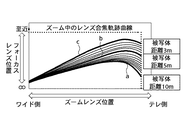
ズームレンズ102の位置とフォーカスレンズ105の位置の関係は図13に示す曲線で表わされる。図14に示す曲線は、曲線a(被写体距離10m)が無限の被写体距離に合焦する位置に対応するもので、曲線b(被写体距離5m),曲線c(被写体距離3m)は、被写体がよりCCD106の撮像面に近い場合の合焦位置に対応するものである。従って、所定の被写体距離の被写体を撮像しながら変倍を行う場合、所定の被写体距離に対応して選択された図14の曲線の軌跡に従ってフォーカスレンズ105を移動すれば合焦状態で変倍を行うことができる。
The relationship between the position of the
そこで、インナーフォーカスレンズを備えた撮像装置は、一般的に、図14に示す複数の軌跡情報を何らかの形(軌跡そのものでも、レンズ位置を変数とした関数でもよい)でレンズ制御用のマイクロコンピュータ(以下「マイコン」という)等に記憶させておき、ズームレンズ102の移動に対応して、その軌跡情報にしたがってフォーカスレンズ105を移動するように制御している。
Therefore, an imaging apparatus equipped with an inner focus lens generally uses a microcomputer for lens control in a form of a plurality of pieces of locus information shown in FIG. 14 (the locus itself or a function with the lens position as a variable). (Hereinafter referred to as “microcomputer”) and the like, and in response to the movement of the
次に、図13のレンズ駆動制御装置におけるステップモータの駆動方法の一例を説明する。 Next, an example of a driving method of the step motor in the lens drive control device of FIG. 13 will be described.
レンズ駆動用のモータとしてステップモータを使用すれば、歩進パルス数に対する回転角度が一定のため、レンズの初期位置を決めれば、その後は歩進パルスをそのままインクリメント又はデクリメントしてパルス数をカウントすることによりレンズ位置の検出を正確に行うことができる。従って、エンコーダを用いる必要がなく、また、レンズ駆動制御が容易である。なお、ステップモータの駆動は、ステップモータに電圧(又は電流)を印加することによって行うが、低騒音で駆動を行うために正弦波形を用いる場合が多い。 If a stepping motor is used as the lens driving motor, the rotation angle with respect to the number of stepping pulses is constant, so once the initial position of the lens is determined, the number of pulses is counted by incrementing or decrementing the stepping pulse as it is. Thus, the lens position can be accurately detected. Therefore, it is not necessary to use an encoder, and lens drive control is easy. Note that the step motor is driven by applying a voltage (or current) to the step motor, but a sinusoidal waveform is often used to drive the step motor with low noise.
図15は、図13のレンズ駆動制御装置におけるステップモータの構成を概略的に示す図である。 FIG. 15 is a diagram schematically showing a configuration of a step motor in the lens drive control device of FIG.
図15のステップモータは、一対のモータ巻線コイル3,4及びマグネット6を有する
2相ステップモータ5と、モータ巻線コイル3に接続されたモータドライバ回路1と、モータ巻線コイル4に接続されたモータドライバ回路2と、モータドライバ回路1,2に夫々接続されたモータ制御を行うマイクロコンピュータ(マイコン)7とを備える。
The step motor shown in FIG. 15 is connected to the two-
マイコン7は、モータの駆動速度や停止位置を制御するためのプログラムを格納するROM、プログラムの制御命令に従って周波数とデューティ比を設定しパルス信号(E、F)を出力するPWM波形生成ユニットと、高(「H」)及び低(「L」)信号出力可能なポート(A、B)とを内蔵している。 The microcomputer 7 includes a ROM that stores a program for controlling the driving speed and stop position of the motor, a PWM waveform generation unit that sets a frequency and a duty ratio according to a control instruction of the program, and outputs a pulse signal (E, F); Ports (A, B) capable of outputting high (“H”) and low (“L”) signals are incorporated.
図16は、図15におけるモータドライバ回路1,2の内部構成を概略的に示す図である。
FIG. 16 schematically shows an internal configuration of
図16のモータドライバ回路1,2は、Vcc端子とGND端子の間に夫々直列に接続された、PNPトランジスタ8,9と、ダイオード12,14と、ダイオード13,15と、NPNトランジスタ10,11とを備え、さらに、出力端がPNPトランジスタ8及びNPNトランジスタ11の各ベースに夫々抵抗16,19を介して接続され、一方の入力端が入力EN1に他方の入力端が入力IN1に接続されたANDゲート20と、出力端がPNPトランジスタ9及びNPNトランジスタ11の各ベースに夫々抵抗18,19を介して接続され、一方の入力端が入力EN1に他方の入力端がNOTゲート22を介して入力IN1に接続されたANDゲート21とを備える。
The
PNPトランジスタ8及びNPNトランジスタ10の接続点は出力OUT1に接続されており、PNPトランジスタ9及びNPNトランジスタ11の接続点は出力OUT2に接続されている。出力OUT1と出力OUT2はモータ巻き線コイル3を介して接続されている。
A connection point between the
以下、図15におけるモータドライバ回路の作動をモータドライバ回路1に着目して説明する。 Hereinafter, the operation of the motor driver circuit shown in FIG.
図16において、入力EN1が「H」レベルで入力IN1が「H」レベルのとき、トランジスタ8及び11はON状態となり、トランジスタ9及び10はOFF状態となる。従って、モータ巻線コイル13にはOUT1からOUT2の方向に電流が流れる。入力EN1が「H」レベルで入力IN1が「L」レベルのときは、トランジスタ9及びトランジスタ10がON状態となり、トランジスタ8及びトランジスタ11がOFF状態となる。従って、モータ巻線コイル3にはOUT2からOUT1の方向に電流が流れる。また、入力EN1が「L」レベルのときは入力IN1の入力レベルに関わらずPNPトランジスタ8,9、NPNトランジスタ10,11はOFF状態となり、出力OUT1,OUT2はハイインピーダンス状態となる。これらの場合の入力と出力との関係を表1に示す。
In FIG. 16, when the input EN1 is “H” level and the input IN1 is “H” level, the

また、マイコン7からモータドライバ回路1,2に対して、パルス幅変調(PWM)出力Eが入力IN1にパルス幅変調(PWM)出力Fが入力IN2に入力される。また、入力EN1、入力EN2は、図15に示すようにマイコン出力ポートA,Bに接続して「H」,「L」を制御してもよく、マイコン7に接続せずに「H」レベルに固定してもよい。
Further, the pulse width modulation (PWM) output E is input to the input IN1 and the pulse width modulation (PWM) output F is input to the input IN2 from the microcomputer 7 to the
以下、図16におけるモータ巻き線コイル3を流れる電流のパルス幅変調による制御方法を説明する。
Hereinafter, a control method by pulse width modulation of the current flowing through the
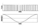
図16において、マイコン7はPWM出力E,Fを一定の周波数fpでモータドライバ回路1,2に入力する。このPWM出力E,Fの「H」,「L」により上述した論理でモータ巻線コイル3,4に電流が流れるが、周波数fpが高いためコイルのインダクタンスの影響でモータ巻線コイル3には図17に示すようなデューティ比に応じた電流が流れる。従って、振動や騒音が小さくなるように正弦波駆動を行うためには、このPWMデューティ比を略正弦波的に変化させれる。またさらに効率よくモータ駆動を行うためには、前記略正弦波の振幅を回転速度に応じて変化するようにPWMデューティ比の変化を調整する。
In FIG. 16, the microcomputer 7 inputs the PWM outputs E and F to the
ズームレンズ102は、画角を変更するときだけ駆動され、また、フォーカスレンズ105は焦点を合わせるときだけ駆動される。従って、画角を決めて一定の被写体距離で被写体を撮像している場合には、ズームレンズ102もフォーカスレンズ105も駆動する必要がない。そこで、レンズを停止しているときには、モータに通電しないようにして無駄な消費電力を抑えるようにするのが一般的である。なお、レンズ停止時にモータへの通電は、図15における入力EN1,EN2を「L」レベルにすることにより禁止することができる。
The
ここで、ステップモータの停止位相をディテント位置だけに限定して停止させる場合にはモータに通電しなくても問題ないが、より細かい分解能の停止位相でモータを停止させる場合、ディテント位置とディテント位置の中間に停止することがある。その場合に、通電を停止した時にいずれかのディテント位置に回転する可能性がある。そこで、1−2相励磁方式のステップモータ制御において、1相励磁位置だけに限定して停止させる方法が提案されている(例えば、特許文献1参照)。
しかしながら、近年ではレンズ及びCCD等の撮像素子の小型化が進むと共に、レンズの高倍率化により、レンズの位置敏感度が大きくなる傾向であり、すなわち、図13に示すレンズ合焦軌跡曲線において、テレ側における曲線の傾きが大きくなる傾向になっている。その結果、より高精度にレンズ駆動制御を行うためには、ズームレンズの制御分解能を高める必要がある。そのためには、レンズを動かすネジピッチを細かくするか、モータの極数を増やすか、モータの位相分解能を細かくすることになる。しかし、ネジピッチを細かくすると同じ速度で動かした時のレンズの移動距離が短くなってしまうため、端から端までの移動時間を従来通りに維持するためには、駆動速度を上げなければならず、騒音の問題が生じる可能性がある。また、モータの極数を増やすと、トルクが弱くなり、高速駆動ができず、端から端までの移動時間が長くなってしまう。従って、騒音の発生を抑えてレンズの移動時間の高速性を保ったまま位相分解能を高めるためには、モータの制御位相を1相励磁位置だけでなく、その1/2、1/4、1/8…と位相分解能を細かくしていかなければならない。 However, in recent years, the lens and CCD and other imaging devices have been miniaturized, and the lens has a higher sensitivity due to the higher magnification. That is, in the lens focus locus curve shown in FIG. The slope of the curve on the tele side tends to increase. As a result, in order to perform lens drive control with higher accuracy, it is necessary to increase the control resolution of the zoom lens. For this purpose, the screw pitch for moving the lens is made finer, the number of poles of the motor is increased, or the phase resolution of the motor is made finer. However, if the screw pitch is made fine, the moving distance of the lens when moving at the same speed will be shortened, so in order to maintain the movement time from end to end as before, the driving speed must be increased, Noise problems can arise. Further, when the number of poles of the motor is increased, the torque becomes weak, high speed driving cannot be performed, and the movement time from end to end becomes longer. Therefore, in order to suppress the generation of noise and increase the phase resolution while maintaining the high speed of the lens movement time, the motor control phase is not only the one-phase excitation position but also 1/2, 1/4, / 8 ... The phase resolution must be made finer.
図18は、図15のステップモータの位相に対する電流の略正弦波形の関係を示すグラフである。 FIG. 18 is a graph showing the relationship of a substantially sinusoidal waveform of the current with respect to the phase of the step motor of FIG.
図18において、2相のステップモータにおいて、A相とB相の片方だけに電流が流れている状態が1相励磁位置の状態であり、略正弦波形では90度毎に位置している。そして、1相励磁位置の中間位置を1/2相位置、更に1相位置と1/2相位置の中間位置を1/4相位置、また、1/4相位置と1相又は1/2相位置との中間位置を1/8相位置という。 In FIG. 18, in the two-phase stepping motor, the state where the current flows only in one of the A phase and the B phase is the state of the one-phase excitation position, and the sine waveform is positioned every 90 degrees. The intermediate position of the 1-phase excitation position is the 1/2 phase position, the intermediate position of the 1 phase position and the 1/2 phase position is the 1/4 phase position, and the 1/4 phase position is 1 phase or 1/2 phase. The intermediate position with respect to the phase position is called 1/8 phase position.
ただし、前述したように、位相分解能を細かくしても、トルクの弱い位相位置でモータを停止して通電をOFF状態にするとディテントトルク位置に引っ張られてモータが回転する可能性がある。 However, as described above, even if the phase resolution is fine, if the motor is stopped at the phase position where the torque is weak and the energization is turned off, the motor may be rotated by being pulled to the detent torque position.
本発明の目的は、レンズ駆動制御を高精度に行うと共に、レンズ群をテレ側端又はワイド側端の停止可能位相位置に停止させることができ、ステップモータの通電を遮断しても、ステップモータがその停止位置において位相がずれるのを防止することができるレンズ駆動制御装置及び方法を提供することにある。 An object of the present invention is to perform lens drive control with high accuracy and to stop the lens group at a stoppable phase position at the tele end or the wide end. Is to provide a lens drive control device and method capable of preventing the phase from being shifted at the stop position.
請求項1記載のレンズ駆動制御装置は、光軸方向に移動する少なくとも1つレンズ群と、前記レンズ群を駆動するステップモータと、前記ステップモータの原点位置を前記ステップモータの制御上の最小位相単位で検出する原点位置検出手段と、前記レンズ群の位置を前記最小位相単位で算出するレンズ位置演算手段と、前記最小位相単位で検出されたステップモータの原点位置を前記最小位相単位よりも粗い位相単位で前記ステップモータの停止可能位相位置又は非停止位相位置に設定する停止位置設定手段とを備えることを特徴とする。
The lens drive control device according to
請求項9記載のレンズ駆動制御方法は、光軸方向に移動する少なくとも1つレンズ群を駆動するステップモータの原点位置を前記ステップモータの制御上の最小位相単位で検出し、前記レンズ群の位置を前記最小位相単位で算出し、前記最小位相単位で検出されたステップモータの原点位置を前記最小位相単位よりも粗い位相単位で前記ステップモータの停止可能位相位置又は非停止位相位置に設定することを特徴とする。 The lens drive control method according to claim 9, wherein an origin position of a step motor for driving at least one lens group moving in the optical axis direction is detected in a minimum phase unit in the control of the step motor, and the position of the lens group is detected. Is calculated in the minimum phase unit, and the origin position of the step motor detected in the minimum phase unit is set to a stoppable phase position or a non-stop phase position of the step motor in a phase unit coarser than the minimum phase unit. It is characterized by.
本発明によれば、ステップモータの原点位置をステップモータの制御上の最小位相単位で検出すると共にレンズ群の位置を最小位相単位で算出し、加えて、ステップモータの停止位置を最小位相単位よりも粗い位相単位でステップモータの停止可能位相位置又は非停止位相位置に設定するので、レンズ駆動制御を高精度に行うと共に、レンズ群をテレ側端又はワイド側端におけるステップモータの停止可能位相位置に停止させることができ、ステップモータの通電を遮断しても、ステップモータがその停止位置において位相がずれるのを防止することができる。 According to the present invention, the origin position of the step motor is detected in the minimum phase unit in the control of the step motor and the position of the lens group is calculated in the minimum phase unit. In addition, the stop position of the step motor is determined from the minimum phase unit. The step motor stop phase position or non-stop phase position is set in coarse phase units, so that the lens drive control is performed with high accuracy and the step motor stop phase position at the tele end or wide end is set. Even if the power supply to the step motor is cut off, it is possible to prevent the step motor from being out of phase at the stop position.
図1は、本発明の実施の形態に係るレンズ駆動制御装置を備える撮像装置の内部構成を概略的に示すブロック図で示したものである。 FIG. 1 is a block diagram schematically showing an internal configuration of an image pickup apparatus including a lens drive control device according to an embodiment of the present invention.
図1において、撮像装置としてのビデオカメラは、被写体側から、第1固定レンズ群101と、変倍を行う変倍レンズ群(ズームレンズ)102と、絞り103と、第2固定レンズ群104と、焦点調節機能及び変倍による焦点面の移動を補正するコンペンセータレンズ機能を兼ね備えた合焦レンズ群(フォーカスレンズ)105と、撮影面を有し、撮影面上に結像された光学的な被写体像を光電変換して映像信号として出力する撮像素子としてのCCD106と、CCD106の出力を増幅する二重相関サンプリング(CDS)自動ゲイン制御回路(AGC)107と、AGC107からの出力信号を後述する記録装置109及びモニタ装置110に対応した信号に変換するカメラ信号処理回路108と、カメラ信号処理回路108によって変換された信号を記録する記録装置109と、カメラ信号処理回路108によって変換された信号を表示するモニタ装置110とを備える。記録装置109は、動画や静止画を記録し、記録媒体としての磁気テープや半導体メモリから成る。
In FIG. 1, a video camera as an imaging apparatus includes a first
図1のビデオカメラは、さらに、ズームレンズ102を駆動するズームモータ117と、ズームモータ駆動用のドライバと、絞り103を駆動するIGメータ121と、IGメータ121用のドライバ120と、AGC107で増幅された映像信号のレベルに基づいてドライバ120に絞り制御信号を送出する絞り制御回路119と、フォーカスレンズ105を駆動するフォーカスモータ118と、フォーカスモータ駆動用のドライバ116と、AGC107で増幅された映像信号から合焦のために最適な信号を取り出す範囲を設定するAFゲート111と、焦点検出に用いられる高周波成分、低周波成分及び輝度差成分(映像信号の輝度レベルの最大値と最小値の差分)を抽出するAF信号処理回路112と、ズームレンズ102及びフォーカスレンズ105の各位置を夫々検出する後述する図2のレンズ位置検出センサ122,123(実施の形態において「リセットセンサ」ともいう)と、ズームモータ駆動用ドライバ115、フォーカスモータ駆動用ドライバ116、AF信号処理回路112、カメラ信号処理回路108、記録装置109、及びレンズ位置検出センサ122,123に夫々接続されたカメラ/AFマイコン113と、カメラ/AFマイコン113に接続されたズームスイッチ114とを備える。
The video camera shown in FIG. 1 is further amplified by a
カメラ/AFマイコン113は、AF信号処理回路112の出力信号に基づいてフォーカスレンズを制御すると共に、ズームスイッチ114の操作情報(操作部材の回転角度に応じた電圧が出力され、この出力電圧に応じて可変速ズームがなされる)を読み込んでズーム制御を行い、また、カメラ信号処理回路108の出力信号を制御する等を行う。AFマイコン113は、AF信号処理回路112の出力信号レベルが最大となるように、フォーカスレンズ105を移動させることにより、自動焦点調節を行っている。
The camera / AF microcomputer 113 controls the focus lens based on the output signal of the AF
AFゲート11は、その大きさが可変であり、また複数設けられることもある。
The size of the
絞り制御回路119は、AGC回路107の出力信号のレベルを検出し、このレベルが一定レベル(適性露光量)でないときは、一定レベルにするための絞り量制御信号をIGドライバ120に出力し、IGメータ121は、適性露光量を維持するように絞り103を駆動する。
The
ドライバ115,116は、夫々カメラ/AFマイコン113から出力されるズームレンズ102及びフォーカスレンズ105の駆動命令に従って駆動エネルギーを波形変更可能な電流としてズームモータ117及びフォーカスモータ118に出力する。
The
図2は、図1におけるレンズ位置検出センサ122の構成を概略的に示す斜視図である。
FIG. 2 is a perspective view schematically showing the configuration of the lens
図2のレンズ位置検出センサ122は、ズームモータ117の原点位置(リセット位置)に配されたフォトセンサ130と、遮光板131とを備える。フォトセンサ130は、発光部132と受光部133とを備え、遮光板131は、ズームレンズ102又はフォーカスレンズ105に固定されていると共に、フォトセンサ130の発光部132と受光部133の間においてズームレンズ102又はフォーカスレンズ105の移動に応じて進退する。ズームレンズ102又はフォーカスレンズ105がテレ側とワイド側の間で光軸方向に移動すると、それと一体に遮光板131が移動し、フォトセンサ130の発光部132及び受光部133間の光路を遮ったとき、受光部133の出力信号は低(「L」)レベルになり、遮らないときは高(「H」)レベルになる。これにより、受光部133の出力信号が変化する位置を基準位置(ズームモータ117の原点位置)として、ズームレンズ102、フォーカスレンズ105が基準位置に存在するか否かを検知することができ、もって、AFマイコン113は、この基準位置と、レンズ移動速度、レンズ移動方向等により、各レンズの位置を認識することができる。
The lens
以上の説明は、レンズ位置検出センサ122に対するものであるが、レンズ位置検出センサ123にも適用される。
The above description is for the lens
AFマイコン113には、ズームレンズ102をワイド側又はテレ側に移動させるためのズームスイッチ114が接続されている。ズームスイッチ114はその押圧に応じて電圧が変化するような回路構成になっており、AFマイコン113はズームスイッチ114が操作された時にその電圧変化を検出し、その電圧に応じて可変速ズームの何速目のズーム速度でズームレンズ102を駆動させるかを決定する。
A zoom switch 114 for moving the
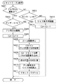
図3は、図1におけるレンズ駆動制御装置によって実行されるレンズ制御処理の手順を示すフローチャートである。 FIG. 3 is a flowchart showing a procedure of lens control processing executed by the lens drive control device in FIG.
本実施の形態では、ステップモータ制御上の最小位相単位を図18における1/8相の単位とし、停止可能位相単位を1/4相の単位とするが、最小位相単位に対して停止可能位相単位が粗い設定であれば、どのような位相単位で制御してもよい。 In the present embodiment, the minimum phase unit in step motor control is the 1/8 phase unit in FIG. 18 and the stoppable phase unit is the 1/4 phase unit, but the stoppable phase with respect to the minimum phase unit. As long as the unit is a rough setting, the control may be performed in any phase unit.
また、以下の説明は、ステップモータの位置カウントがワイド側からテレ側方向に増加する場合を対象としているが、テレ側からワイド側方向に増加する場合もこれに準ずる。ただし、その場合には、以下の説明において、カウンタのプラスとマイナスの符号が逆になる。 Further, the following description is directed to the case where the position count of the step motor increases from the wide side to the tele side direction, but the same applies to the case where the step motor increases from the tele side to the wide side direction. However, in that case, in the following description, the plus and minus signs of the counter are reversed.
図3において、まず、電源がON状態になると(ステップS301でYES)、ステップモータをその原点位置に移動する(リセットする)ことを1で示すリセットフラグを「1」に設定し(ステップS302)、リセットモードを「1」に設定し(ステップS303)、パルスカウンタ0を1相励磁位置にしてステップモータの位相を初期化する(ステップS304)。
In FIG. 3, first, when the power is turned on (YES in step S301), a reset flag indicating 1 to move (reset) the step motor to its origin position is set to “1” (step S302). The reset mode is set to “1” (step S303), the
次いで、レンズ駆動制御装置を撮像素子としてのCCD106の画像取り込み周期に同期させて実行するために1V周期期間(垂直同期期間)待機した(ステップS305でYES)後、リセットフラグが「1」であるか否かを判別する(ステップS306)。最初は、リセットフラグが「1」であるので、リセットを行うべく、リセットモードの値が「1」か、「2」か、「3」かを判別し(ステップS307)、最初は、リセットモードが「1」であるので、後述する図4のリセットモード1処理を実行する(ステップS308)。
Then, after waiting for 1 V period (vertical synchronization period) to execute the lens drive control device in synchronization with the image capturing period of the
ステップS306の判別の結果、リセットフラグが1でないときは、後述する図8の通常動作処理を実行し(ステップS311)、次いで、電源がOFF状態であるか否かを判別し(ステップS312)、OFF状態でなければ、ステップS305以降の処理を繰り返し、電源がOFF状態であれば、本処理を終了する。 If the result of determination in step S306 is that the reset flag is not 1, normal operation processing of FIG. 8 described later is executed (step S311), and then it is determined whether or not the power is off (step S312). If it is not in the OFF state, the processing from step S305 is repeated, and if the power is in the OFF state, this processing is terminated.
図4は、図3のステップS308で実行されるリセットモード1処理の手順を示すフローチャートである。
FIG. 4 is a flowchart showing the procedure of the
図4において、まず、リセットセンサ(図1におけるレンズ位置検出センサ122、以下同様)の出力が「H」であるか否かを判別する。本実施の形態では、ステップモータの位置カウントがワイド側からテレ側方向に増加する場合を想定しているので、ステップS401の判別の結果は、リセットセンサが「H」であるので、テレ側方向への駆動命令を送出し(ステップS402)、リセット動作時の駆動速度で1V期間に進むパルス数をA(最小位相単位(1/8相)の整数倍)とし、Aパルス加算した位置を目標位置(Cz←Cz+A)としてズームモータ117を駆動し(ステップS403)、ステップS404に進む。
In FIG. 4, first, it is determined whether or not the output of the reset sensor (lens
ステップS401の判別の結果、リセットセンサの出力が「L」であるときは、ワイド側方向への駆動命令を送出し(ステップS405)、リセット動作時の駆動速度で1V期間に進むパルス数をA(最小位相単位(1/8相)の整数倍)とし、Aパルス減算した位置を目標位置(Cz←Cz−A)としてズームモータ117を駆動して(ステップS406)、ステップS404に進む。
If the result of determination in step S401 is that the output of the reset sensor is “L”, a drive command in the wide side direction is sent (step S405), and the number of pulses that advance in the 1V period at the drive speed during the reset operation is A The
続くステップS404では、リセットモードを「2」に設定し、その後、本処理を終了して、図3のステップS305以降の処理を実行する。この場合、ステップS307の判別の結果、リセットモードが「2」であるので、後述する図5のリセットモード2処理を実行する(ステップS309)。
In the subsequent step S404, the reset mode is set to “2”, and then this process is terminated, and the processes in and after step S305 in FIG. 3 are executed. In this case, since the reset mode is “2” as a result of the determination in step S307, the
図5は、図3のステップS309で実行されるリセットモード2処理の手順を示すフローチャートである。
FIG. 5 is a flowchart showing the procedure of the
図5において、まず、ステップモータが1V前に設定された目標位置に到達しているものとして、1V前のステップモータの駆動方向がテレ側方向か否かを判別する(ステップS501)。この場合、駆動方向がテレ側方向なので、リセットセンサの出力が「H」から「L」に切り替わっているか否かを判別する(ステップS502)。 In FIG. 5, first, it is determined whether or not the driving direction of the step motor 1V before is the tele side direction, assuming that the step motor has reached the target position set 1V before (step S501). In this case, since the driving direction is the tele-side direction, it is determined whether or not the output of the reset sensor is switched from “H” to “L” (step S502).
ステップS502の判別の結果、リセットセンサの出力が「H」から「L」に切り替わっていないときは、テレ側方向への駆動命令を送出し(ステップS503)、リセット動作時の駆動速度で1V期間に進むパルス数をA(最小位相単位(1/8相)の整数倍)とし、Aパルス加算した位置を目標位置(Cz←Cz+A)としてモータを駆動して(ステップS504)、このステップS503〜S504の処理を、リセットセンサの出力が「H」から「L」に切り替わる(ステップS502でYES)まで繰り返す。 If the output of the reset sensor has not switched from “H” to “L” as a result of the determination in step S502, a driving command in the tele direction is sent (step S503), and the driving speed at the time of reset operation is 1 V period The number of pulses going to A is A (integer multiple of minimum phase unit (1/8 phase)), and the motor is driven with the position obtained by adding A pulses as the target position (Cz ← Cz + A) (step S504). The process of S504 is repeated until the output of the reset sensor switches from “H” to “L” (YES in step S502).
ステップS502の判別の結果、リセットセンサの出力が「H」から「L」に切り替わると(ステップモータモータの原点位置を越えると)、ワイド側方向への駆動命令を送出し(ステップS505)、最小位相単位で1パルス分(1/8相分)減算した位置を目標位置(Cz←Cz−1)としてモータを駆動して(ステップS504)、ステップS507に進む。 When the output of the reset sensor switches from “H” to “L” as a result of the determination in step S502 (when the origin of the step motor motor is exceeded), a drive command in the wide side direction is sent (step S505), and the minimum The motor is driven with the position obtained by subtracting one pulse (1/8 phase) in phase units as the target position (Cz ← Cz−1) (step S504), and the process proceeds to step S507.
ステップS501の判別の結果、ステップモータの駆動方向がワイド側方向のときは、リセットセンサの出力が「L」から「H」に切り替わっているか否かを判別する(ステップS508)。 If the result of the determination in step S501 is that the stepping motor is driven in the wide side direction, it is determined whether or not the output of the reset sensor has been switched from “L” to “H” (step S508).
ステップS508の判別の結果、リセットセンサの出力が「L」から「H」に切り替わっていないときは、ワイド側方向への駆動命令を送出し(ステップS509)、リセット動作時の駆動速度で1V期間に進むパルス数をA(最小位相単位(1/8相)の整数倍)とし、Aパルス減算した位置を目標位置(Cz←Cz−A)としてモータを駆動して(ステップS510)、このステップS509〜S510の処理をリセットセンサの出力が「L」から「H」に切り替わる(ステップS508でYES)まで繰り返す。 If the output of the reset sensor has not switched from “L” to “H” as a result of the determination in step S508, a drive command in the wide side direction is sent out (step S509), and the drive speed during the reset operation is 1 V period The number of pulses to go to A is an integer multiple of the minimum phase unit (1/8 phase), and the motor is driven with the position obtained by subtracting the A pulse as the target position (Cz ← Cz−A) (step S510). The processes of S509 to S510 are repeated until the output of the reset sensor switches from “L” to “H” (YES in step S508).
ステップS508の判別の結果、リセットセンサの出力が「L」から「H」に切り替わると(ステップモータモータの原点位置を越えると)、テレ側方向への駆動命令を送出し(ステップS511)、最小位相単位で1パルス分(1/8相分)加算した位置を目標位置(Cz←Cz+1)としてモータを駆動して(ステップS512)、ステップS507に進む。 If the output of the reset sensor switches from “L” to “H” as a result of the determination in step S508 (when the origin of the step motor motor is exceeded), a driving command in the tele direction is sent (step S511), and the minimum The motor is driven with the position obtained by adding one pulse (for 8 phase) in phase units as the target position (Cz ← Cz + 1) (step S512), and the process proceeds to step S507.
続くステップS507では、リセットモードを「3」とし、本処理を終了して、その後、図3のステップS305以降の処理を実行する。この場合、ステップS307の判別の結果、リセットモードが「3」であるので、後述する図6のリセットモード3処理を実行する。
In the subsequent step S507, the reset mode is set to “3”, this process is terminated, and thereafter, the processes after step S305 in FIG. 3 are executed. In this case, since the reset mode is “3” as a result of the determination in step S307, the
図6は、図3のステップS310で実行されるリセットモード3処理の手順を示すフローチャートである。
FIG. 6 is a flowchart showing the procedure of the
図6において、まず、ステップモータが1V前に設定された目標位置に到達しているものとして、1V前のステップモータの駆動方向がテレ側方向か否かを判別する(ステップS601)。この場合、ステップモータの駆動方向がワイド側方向なので、リセットセンサの出力が「L」から「H」に切り替わっているか否かを判別する(ステップS612)。 In FIG. 6, first, it is determined whether or not the driving direction of the step motor 1V before is the tele side direction, assuming that the step motor has reached the target position set 1V before (step S601). In this case, since the driving direction of the step motor is the wide side direction, it is determined whether or not the output of the reset sensor is switched from “L” to “H” (step S612).
ステップS612の判別の結果、リセットセンサの出力が「L」から「H」に切り替わっていないときは、ワイド側方向への駆動命令を送出し(ステップS613)、最小位相単位で1パルス分(1/8相分)減算した位置を目標位置(Cz←Cz−1)としてモータを駆動して(ステップS614)、ステップS613〜S614の処理をリセットセンサの出力が「L」から「H」に切り替わる(ステップS612でYES)まで繰り返す。 If the output of the reset sensor has not changed from “L” to “H” as a result of the determination in step S612, a drive command in the wide side direction is sent (step S613), and one pulse (1 The motor is driven with the subtracted position as the target position (Cz ← Cz-1) (step S614), and the output of the reset sensor switches from "L" to "H" in steps S613 to S614. Repeat until (YES in step S612).
ステップS601の判別の結果、駆動方向がテレ側方向のときは、リセットセンサの出力が「H」から「L」に切り替わっているか否かを判別する(ステップS602)。 As a result of the determination in step S601, when the driving direction is the tele side direction, it is determined whether or not the output of the reset sensor is switched from “H” to “L” (step S602).
ステップS602の判別の結果、リセットセンサの出力が「H」から「L」に切り替わっていないときは、テレ側方向への駆動命令を送出し(ステップS603)、最小位相単位で1パルス分(1/8相分)加算した位置を目標位置(Cz←Cz+1)としてモータを駆動して(ステップS605)、このステップS604〜S605の処理をリセットセンサの出力が「H」から「L」に切り替わる(ステップS602でYES)まで繰り返す。 If the output of the reset sensor is not switched from “H” to “L” as a result of the determination in step S602, a drive command in the tele direction is sent (step S603), and one pulse (1 / 8 phase) The motor is driven with the added position as the target position (Cz ← Cz + 1) (step S605), and the process of steps S604 to S605 switches the output of the reset sensor from “H” to “L” ( Repeat until YES in step S602.
ステップS602の判別の結果、リセットセンサの出力が「H」から「L」に切り替わっているとき、又は、ステップS612の判別の結果、リセットセンサの出力が「L」から「H」に切り替わっているときは(ステップモータの原点位置を越えているときは)、ズーム駆動を停止し(ステップS606)、リセット位置(「H」から「L」へ、又は「L」から「H」への切換えを検出した位置)Czの位相をC0としてメモリに記憶し(ステップS607)、事前に記憶されているリセット位置カウンタをパルス値P0として書き込み(ステップS608)、ステップS607で記憶した位相C0とステップS608で書き込んだパルス値P0からステップモータの現在位置の位相を後述する算出方法により計算し(ステップS609)、後述する図7のテレ側端及びワイド側端算出処理を実行して、テレ側端及びワイド側端の位置を算出し(ステップS610)、最後に、リセットフラグを「0」に設定して(ステップS611)、本処理を終了する。 As a result of the determination in step S602, when the output of the reset sensor is switched from “H” to “L”, or as a result of the determination in step S612, the output of the reset sensor is switched from “L” to “H”. When (when it exceeds the origin position of the step motor), the zoom drive is stopped (step S606), and the reset position ("H" to "L" or "L" to "H" is switched). (Detected position) The phase of Cz is stored in the memory as C0 (step S607), the reset position counter stored in advance is written as the pulse value P0 (step S608), and the phase C0 stored in step S607 and step S608 are stored. The phase of the current position of the step motor is calculated from the written pulse value P0 by a calculation method described later (step S609). The tele side end and wide side end calculation processing of FIG. 7 described later is executed to calculate the positions of the tele side end and the wide side end (step S610), and finally the reset flag is set to “0” ( Step S611), the process is terminated.
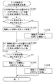
図7は、図6のステップS610で実行されるテレ側端又はワイド側端算出処理の手順を示すフローチャートである。 FIG. 7 is a flowchart showing the procedure of the tele-side end or wide-side end calculation process executed in step S610 of FIG.
図7において、まず、ステップS607で記憶したリセット位置Czの位相C0に、光学テレ側端位置とリセット位置との間のパルスカウント値を正弦波1周期のパルス数(1/8相単位の場合は1周期に32パルス数)で割ったときの余りから求めた位相を加算することにより、光学テレ側端位置の位相を計算し(ステップS701)、ステップS701で計算した光学テレ側端位置の位相がステップモータの停止可能位相であるか否かを判別し(ステップS702)、停止可能位相であるときは、光学テレ側端をそのまま実際の駆動上のテレ側端位置として設定する(ステップS703)と共に、停止可能な位相位置でないときは、実際の駆動上のテレ側端位置を光学テレ側端位置から1パルス分(1/8相分)ワイド側にずらした位置として(ステップS704)、ステップS705に進む。 In FIG. 7, first, the pulse count value between the optical telephoto end position and the reset position is set to the phase C0 of the reset position Cz stored in step S607, and the number of pulses in one cycle of the sine wave (in the case of 1/8 phase unit). Is calculated by adding the phase obtained from the remainder when divided by the number of 32 pulses in one cycle (step S701), and calculating the phase of the optical tele end position calculated in step S701. It is determined whether or not the phase is a stoppable phase of the step motor (step S702). If the phase is the stoppable phase, the optical tele end is set as it is as the actual tele end position on driving (step S703). If the phase position is not stoppable, the actual telephoto end position is shifted from the optical telephoto end position by one pulse (1/8 phase) to the wide side. To (step S704), the process proceeds to step S705.
次いで、ステップS609で記憶したリセット位置の位相C0から、光学ワイド側端位置とリセット位置との間のパルスカウント値を光学テレ側端位置とリセット位置との間のパルスカウント値を正弦波1周期のパルス数(1/8相単位の場合は1周期に32パルス数)で割ったときの余りから求めた位相を減算することにより、光学ワイド側端位置におけるステップモータの位相を計算し(ステップS705)、ステップS705で計算した光学ワイド側端位置の位相がステップモータの停止可能な位相であるか否かを判別し(ステップS706)、停止可能位相位置であれば、光学ワイド側端をそのまま実際の駆動上のワイド側端位置として設定する(ステップS707)と共に、停止可能位相位置でないときは、実際の駆動上のワイド側端位置を光学ワイド側端位置から1パルス分(1/8相分)テレ側にずらした位置して(ステップS708)、本処理を終了する。 Next, from the phase C0 of the reset position stored in step S609, the pulse count value between the optical wide side end position and the reset position is set as the pulse count value between the optical tele side end position and the reset position as one sine wave cycle. The phase of the step motor at the optical wide side end position is calculated by subtracting the phase obtained from the remainder when divided by the number of pulses (32 pulses per cycle in the case of 1/8 phase) (step S705), it is determined whether or not the phase of the optical wide side end position calculated in step S705 is a phase where the step motor can be stopped (step S706). It is set as the wide end position on the actual drive (step S707), and when it is not the stoppable phase position, the actual wide position on the drive is set. One pulse end position from the optical wide side end position (1/8 phase) positioned shifted to the telephoto side (step S 708), the process ends.
図7の処理によれば、光学テレ側端及びワイド側端におけるステップモータの位相が非停止位相であるときは、テレ側端及びワイド側端位置を実際の光学テレ側端及びワイド側端位置よりも内側(ステップモータの原点位置側)に設定する。 According to the processing of FIG. 7, when the phase of the step motor at the optical tele end and the wide end is a non-stop phase, the tele end and wide end positions are changed to the actual optical tele end and wide end positions. Set to the inner side (step motor origin position side).
以下、リセット位置の位相とテレ側端及びワイド側端を含めた停止位置の関係を表2に示す。 The relationship between the phase of the reset position and the stop position including the tele side end and the wide side end is shown in Table 2 below.
前述した現在位置におけるステップモータの位相、及び光学テレ側端及び光学ワイド側端位置におけるステップモータの位相は、リセット位置を検出した時の位相と記憶されているリセット位置カウンタによって、表2の関係から停止位相であるか否かを判断することができる。 The phase of the step motor at the current position and the phase of the step motor at the optical telephoto side end and the optical wide side end position are as shown in Table 2 according to the phase when the reset position is detected and the stored reset position counter. From this, it can be determined whether or not it is a stop phase.
なお、本実施の形態では、ステップモータの最小位相単位を図18における1/8相の単位とし、停止位相を1/4相の単位とする場合で説明したが、他の位相関係による制御であっても表2で説明したことと同様な考え方で、停止位相を算出することが容易にできる。 In the present embodiment, the minimum phase unit of the step motor is described as a 1/8 phase unit in FIG. 18 and the stop phase is set as a 1/4 phase unit. Even if it exists, it is possible to easily calculate the stop phase based on the same concept as described in Table 2.
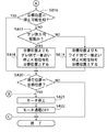
図8及び図9は、図6のステップS311で実行される通常動作処理の手順を示すフローチャートである。 8 and 9 are flowcharts showing the procedure of the normal operation process executed in step S311 of FIG.
図8において、現在のレンズ位置を読み出し(ステップS801)、次いで、ズームスイッチ114が操作されているか否かによって、ズーム命令を受けている否かを判別し(ステップS802)、ズーム命令を受けているときは、ステップS803以降のズーム処理を実行し、ズーム命令を受けていないときは、ステップS816以降のフォーカス処理を実行する。 In FIG. 8, the current lens position is read (step S801), and then whether or not a zoom command is received is determined based on whether or not the zoom switch 114 is operated (step S802). If the zoom command is received, the zoom process after step S803 is executed. If the zoom command is not received, the focus process after step S816 is executed.
以下、図8のステップS803以降のズーム処理を説明する。 Hereinafter, zoom processing after step S803 in FIG. 8 will be described.
まず、モータへの通電をONにして(ステップS803)、ズームスイッチ114の操作状態に応じてモータの駆動速度を設定し(ステップS804)、ズームの操作方向がテレ側方向か否かを判別する(ステップS805)。 First, energization of the motor is turned on (step S803), the motor drive speed is set according to the operation state of the zoom switch 114 (step S804), and it is determined whether or not the zoom operation direction is the tele side direction. (Step S805).
ステップS805の判別の結果、ズームレンズ102の駆動方向がテレ側方向のときは、ズームレンズ102の現在位置が駆動上のテレ側端位置であるか否かを判別し(ステップS806)、テレ側端位置でなければ、現在の位置に対してパルス数Bだけ大きい値であって、2V周期後には到達しているパルス数の値)を加算した位置を目標位置(Cz←Cz+B)とし(ステップS807)、目標位置Czがテレ側端位置を越えているか否かを判別し(ステップS808)、超えていれば、目標位置Czを駆動上のテレ側端位置としてリミットチェックをした(ステップS809)後、越えていなければ直ちに、ズームレンズ102の駆動方向を記憶して(ステップS8014)、ズームレンズ102の現在位置が目標位置Czになるまでズームモータ117を駆動させて(ステップS815)、本処理を終了する。
If the result of determination in step S805 is that the driving direction of the
ステップS807において、ステップS804で設定した駆動速度で1V期間に進むパルス数よりも+α(1V期間に進むパルス数よりも小さいパルス数B)を加算して算出した目標位置Czの値は、最小位相単位(1/8相)ではなく、より細かな小数値であってもよい。これは、1V期間後に停止せずに連続的にズームモータ117を駆動させるためである。
In step S807, the value of the target position Cz calculated by adding + α (number of pulses B smaller than the number of pulses proceeding to the 1V period) at the driving speed set in step S804 is less than the minimum phase. Instead of the unit (1/8 phase), a smaller decimal value may be used. This is because the
ステップS805の判別の結果、ズームレンズ102の駆動方向がテレ側方向でなくワイド側方向であるときは、ズームレンズ102の現在位置が駆動上のワイド側端位置であるか否かを判別し(ステップS810)、ワイド側端位置でなければ、現在の位置から上記パルス数Bだけ大きい値であって、2V周期後には到達しているパルス数の値)を減算した位置を目標位置(Cz←Cz−B)とし(ステップS811)、目標位置Czがワイド側端位置を下回っているか否かを判別し(ステップS812)、下回っていれば、目標位置Czを駆動上のワイド側端位置としてリミットチェックをした(ステップS813)後、下回っていなければ直ちに、ズームレンズ102の駆動方向を記憶して(ステップS8014)、ズームレンズ102の現在位置が目標位置Czになるまでズームモータ117を駆動させて(ステップS815)、本処理を終了する。
If the result of determination in step S805 is that the drive direction of the
ステップS806の判別の結果、ズームレンズ102の現在位置が駆動上のテレ側端位置であるとき、又はステップS810の判別の結果、ズームレンズ102の現在位置が駆動上のワイド側端位置であるときは、ズームモータ117を停止して(ステップS821)、ズームモータ117への通電をOFF状態にした(ステップS822)後、本処理を終了する。
As a result of the determination in step S806, when the current position of the
以下、図9のステップS816以降のフォーカス処理を説明する。 Hereinafter, the focus processing after step S816 in FIG. 9 will be described.
まず、1V前に設定した目標位置におけるステップモータの位相が停止可能位相であるか否かを判別し、停止可能位相でないときは、ステップS814で記憶した駆動方向がテレ側方向であったか否かを判別し、テレ側方向であるときは、ステップS807で設定していた目標位置Czよりもテレ側で一番近いステップモータの停止可能位相位置を目標位置する(ステップS818)と共に、テレ側以上でなくワイド側方向であるときは、ステップS811で設定していた目標位置よりもワイド側で一番近い停止可能位相位置を目標位置として(ステップS819)、ステップS820に進む。 First, it is determined whether or not the phase of the step motor at the target position set 1V before is a stoppable phase. If it is not the stoppable phase, it is determined whether or not the drive direction stored in step S814 is the tele side direction. If it is determined that the direction is the tele-side direction, the stop position position of the step motor closest to the tele-side than the target position Cz set in step S807 is set as the target position (step S818), and at the tele-side or higher. If it is in the wide side direction, the stoppable phase position closest to the wide side than the target position set in step S811 is set as the target position (step S819), and the process proceeds to step S820.
ステップS816の判別の結果、1V前に設定した目標位置が停止可能位相であるときは、ステップS817〜S819をスキップして、直ちにステップS820に進む。 As a result of the determination in step S816, when the target position set 1V before is the stoppable phase, steps S817 to S819 are skipped and the process immediately proceeds to step S820.
ステップS820では、ズームレンズ102の現在位置Czが目標位置になったか否かを判別し、目標位置になっていれば、ズームモータ117を停止して(ステップS821)、ズームモータ117への通電をOFF状態にした(ステップS822)後、目標位置になっていなければ直ちに、本処理を終了する。
In step S820, it is determined whether or not the current position Cz of the
本実施の形態によれば、ステップモータ117のリセット位置をステップモータ117の最小位相単位で検出すると共にズームレンズ105の位置を最小位相単位で算出し、加えて、ステップモータ117のテレ側端及びワイド側端位置を最小位相単位よりも粗い位相単位でステップモータ117の停止可能位相位置又は非停止位相位置に設定するので、レンズ駆動制御を高精度に行うと共に、ズームレンズ105をテレ側端又はワイド側端におけるステップモータ117の停止可能位相位置に停止させることができ、ステップモータの通電を遮断しても、ステップモータがその停止位置において位相がずれるのを防止することができる。
According to the present embodiment, the reset position of the
上記実施の形態は、ズームレンズ102及びリセット位置検出センサ122を対象としているが、フォーカスレンズ105及びリセット位置検出センサ123も同様である。
The above embodiment is directed to the
図10は、図7のテレ側端及びワイド側端算出処理の第1の変形例の手順を示すフローチャートである。 FIG. 10 is a flowchart showing the procedure of a first modification of the tele-side end and wide-side end calculation processing of FIG.
図7の処理では、テレ側端・ワイド側端位置が実際の光学設計上のテレ側端・ワイド側端位置よりも内側に設定されるので、ズームストロークが狭くなるので、本処理では、ズームストロークを維持したままテレ側端・ワイド側端位置をシフトさせるものである。 In the processing of FIG. 7, the tele-side end and the wide-side end position are set inside the actual optical design tele-side end and wide-side end position, so the zoom stroke is narrowed. The tele end / wide end position is shifted while maintaining the stroke.
図10の処理は、図10のステップS1001〜S1008が図7のステップS701〜S708に夫々対応しており、図7の処理と基本的に同様である。異なる点は、駆動ワイド側端の算出方法だけであり、以下、その点のみを説明する。 In the process of FIG. 10, steps S1001 to S1008 of FIG. 10 correspond to steps S701 to S708 of FIG. 7, respectively, and are basically the same as the process of FIG. The only difference is the calculation method of the driving wide side end, and only this point will be described below.
図10において、ステップS1006の判別の結果、ステップS1005で計算した光学ワイド側端位置におけるステップモータの位相が停止可能位相でないときは、実際の駆動上のワイド側端位置を光学ワイド側端位置から1パルス分(1/8相分)ワイド側にずらして(ステップS1008)、本処理を終了する。 In FIG. 10, when the phase of the step motor at the optical wide side end position calculated in step S1005 is not a stoppable phase as a result of the determination in step S1006, the actual wide side end position on driving is determined from the optical wide side end position. After shifting by one pulse (1/8 phase) to the wide side (step S1008), this process is terminated.
図10の処理によれば、計算した光学テレ側端位置及び光学ワイド側端位置におけるステップモータの位相が夫々停止可能位相でないときは(ステップS1002及びS1006で夫々NO)、駆動テレ側端をワイド側にずらす(ステップS1004)と共に、駆動ワイド側端もワイド側にずらす(ステップS1008)ので、て、ズームレンズ102のズームストロークを維持することができる。
According to the processing of FIG. 10, when the phase of the step motor at the calculated optical tele end position and optical wide end position is not a stoppable phase (NO in steps S1002 and S1006, respectively), the driving tele end is set wide. Since the driving wide side end is also shifted to the wide side (step S1008), the zoom stroke of the
図11は、図7のテレ側端及びワイド側端算出処理の第2の変形例の手順を示すフローチャートである。 FIG. 11 is a flowchart showing the procedure of the second modification of the tele-side end and wide-side end calculation processing of FIG.
図11の処理では、ズームストロークを維持したままテレ側端・ワイド側端位置をシフトさせる点では、図10の処理と同様であるが、テレ側端側にメカ端余裕が広いレンズの場合には、同様にズームストロークを維持したまま、テレ側端・ワイド側端の位置をテレ方向にずらすことも可能である。 The processing in FIG. 11 is the same as the processing in FIG. 10 in that the tele-side end and the wide-side end position are shifted while maintaining the zoom stroke, but in the case of a lens with a wide mechanical end margin on the tele-side end side. Similarly, it is possible to shift the positions of the tele end and the wide end in the tele direction while maintaining the zoom stroke.
図11の処理は、図11のステップS1101〜S1108が図7のステップS701〜S708に夫々対応しており、図7の処理と基本的に同様である。異なる点は、駆動テレ側端の算出方法だけであり、以下、その点のみを説明する。 In the process of FIG. 11, steps S1101 to S1108 of FIG. 11 correspond to steps S701 to S708 of FIG. 7, respectively, and are basically the same as the process of FIG. The only difference is the method of calculating the driving tele end, and only that point will be described below.
図11において、ステップS1102の判別の結果、ステップS1101で計算した光学テレ側端位置におけるステップモータの位相が停止可能位相でないときは、実際の駆動上のワイド側端位置を光学ワイド側端位置から1パルス分(1/8相分)テレ側にずらして(ステップS1104)、ステップS1105以降の処理を実行して、本処理を終了する。 In FIG. 11, when the phase of the step motor at the optical tele end position calculated in step S1101 is not a stoppable phase as a result of the determination in step S1102, the actual wide side end position on the drive is determined from the optical wide end position. Shift to the tele side for 1 pulse (1/8 phase) (step S1104), execute the processing after step S1105, and end this processing.
図11の処理によれば、計算した光学テレ側端位置及び光学ワイド側端位置におけるステップモータの位相が夫々停止可能位相でないときは(ステップS1102及びS1206で夫々NO)、駆動テレ側端をテレ側にずらす(ステップS1204)と共に、駆動ワイド側端もテレ側にずらす(ステップS1208)ので、ズームレンズ102のズームストロークを維持つつテレ側端及びワイド側端位置をテレ側方向にずらすことができる。
According to the process of FIG. 11, when the phase of the step motor at the calculated optical tele end position and optical wide end position is not a stoppable phase (NO in steps S1102 and S1206, respectively), the driving tele end is set to telephoto. Since the driving wide side end is also shifted to the tele side (step S1208), the tele side end and the wide side end position can be shifted in the tele side direction while maintaining the zoom stroke of the
図12は、図7のテレ側端及びワイド側端算出処理の第3の変形例の手順を示すフローチャートである。 FIG. 12 is a flowchart showing the procedure of the third modification of the tele-side end and wide-side end calculation process of FIG.
図7の処理では、テレ側端・ワイド側端位置が実際の光学設計上のテレ側端・ワイド側端位置よりも内側に設定されるので、設計上のズームストロークが狭くなるが、本処理では、ズームストロークを拡大するようにテレ側端・ワイド側端位置をずらすものである。 In the processing of FIG. 7, the tele-side end and the wide-side end position are set on the inner side of the actual optical design tele-side end and wide-side end position. Then, the tele end and the wide end are shifted so as to enlarge the zoom stroke.
図12の処理は、図9のステップS1201〜S1208が図7のステップS701〜S708に夫々対応しており、図7の処理と基本的に同様である。異なる点は、駆動テレ側端及び駆動ワイド側端の算出方法だけであり、以下、その点のみを説明する。 In the processing of FIG. 12, steps S1201 to S1208 in FIG. 9 correspond to steps S701 to S708 in FIG. 7, respectively, and are basically the same as the processing in FIG. The only difference is the calculation method for the driving tele end and the driving wide end, and only this point will be described below.
図12において、ステップS1202の判別の結果、ステップS1201で計算した光学テレ側端位置におけるステップモータの位相が停止可能位相であるときは、実際の駆動上のワイド側端位置を光学ワイド側端位置から1パルス分(1/8相分)テレ側にずらして(ステップS1204)、ステップS1205に進む。 In FIG. 12, as a result of the determination in step S1202, when the phase of the step motor at the optical telephoto end position calculated in step S1201 is a stoppable phase, the actual wide side end position on driving is set to the optical wide side end position. 1 pulse (1/8 phase) from the tele side (step S1204), and the process proceeds to step S1205.
また、ステップS1206の判別の結果、ステップS1205で計算した光学ワイド側端位置におけるステップモータの位相が停止可能位相であるときは、実際の駆動上のワイド側端位置を光学ワイド側端位置から1パルス分(1/8相分)ワイド側にずらして(ステップS1208)、本処理を終了する。 As a result of the determination in step S1206, when the phase of the step motor at the optical wide side end position calculated in step S1205 is a stoppable phase, the actual driving wide side end position is set to 1 from the optical wide side end position. The pulse (1/8 phase) is shifted to the wide side (step S1208), and this process ends.
図12の処理によれば、計算した光学テレ側端位置及び光学ワイド側端位置におけるステップモータの位相が夫々停止可能位相であるときは(ステップS1202及びS1206で夫々NO)、駆動テレ側端をテレ側にずらす(ステップS1204)と共に、駆動ワイド側端をワイド側にずらす(ステップS1208)ので、ズームレンズ102のズームストロークを拡大することができ、もって実質的な駆動倍率を増加させることができる。
According to the processing of FIG. 12, when the phase of the step motor at the calculated optical tele end position and optical wide end position is a stoppable phase (NO in steps S1202 and S1206, respectively), the driving tele end is Since the driving wide side end is shifted to the wide side (step S1208) as well as shifting to the tele side (step S1204), the zoom stroke of the
101 第1固定レンズ群
102 変倍レンズ群(ズームレンズ)
104 第2固定レンズ群
105 合焦レンズ群(フォーカスレンズ)
113 カメラ/AFマイコン
114 ズームスイッチ
117 ズームモータ
118 フォーカスモータ
122,123 レンズ位置検出センサ
101 First fixed
104 Second fixed
113 Camera / AF microcomputer 114
Claims (9)
Priority Applications (1)
| Application Number | Priority Date | Filing Date | Title |
|---|---|---|---|
| JP2005016133A JP4612843B2 (en) | 2005-01-24 | 2005-01-24 | Lens drive control apparatus and method |
Applications Claiming Priority (1)
| Application Number | Priority Date | Filing Date | Title |
|---|---|---|---|
| JP2005016133A JP4612843B2 (en) | 2005-01-24 | 2005-01-24 | Lens drive control apparatus and method |
Publications (3)
| Publication Number | Publication Date |
|---|---|
| JP2006201722A true JP2006201722A (en) | 2006-08-03 |
| JP2006201722A5 JP2006201722A5 (en) | 2008-03-06 |
| JP4612843B2 JP4612843B2 (en) | 2011-01-12 |
Family
ID=36959738
Family Applications (1)
| Application Number | Title | Priority Date | Filing Date |
|---|---|---|---|
| JP2005016133A Expired - Fee Related JP4612843B2 (en) | 2005-01-24 | 2005-01-24 | Lens drive control apparatus and method |
Country Status (1)
| Country | Link |
|---|---|
| JP (1) | JP4612843B2 (en) |
Cited By (1)
| Publication number | Priority date | Publication date | Assignee | Title |
|---|---|---|---|---|
| WO2021172029A1 (en) * | 2020-02-27 | 2021-09-02 | 日本電産サーボ株式会社 | Motor drive device |
Citations (3)
| Publication number | Priority date | Publication date | Assignee | Title |
|---|---|---|---|---|
| JPH07234353A (en) * | 1994-02-22 | 1995-09-05 | Kyocera Corp | Zoom lens drive controller |
| JPH10224680A (en) * | 1997-02-12 | 1998-08-21 | Asahi Optical Co Ltd | Focus adjustment device for camera |
| JP2001004896A (en) * | 1999-06-21 | 2001-01-12 | Sony Corp | Imaging lens device |
-
2005
- 2005-01-24 JP JP2005016133A patent/JP4612843B2/en not_active Expired - Fee Related
Patent Citations (3)
| Publication number | Priority date | Publication date | Assignee | Title |
|---|---|---|---|---|
| JPH07234353A (en) * | 1994-02-22 | 1995-09-05 | Kyocera Corp | Zoom lens drive controller |
| JPH10224680A (en) * | 1997-02-12 | 1998-08-21 | Asahi Optical Co Ltd | Focus adjustment device for camera |
| JP2001004896A (en) * | 1999-06-21 | 2001-01-12 | Sony Corp | Imaging lens device |
Cited By (1)
| Publication number | Priority date | Publication date | Assignee | Title |
|---|---|---|---|---|
| WO2021172029A1 (en) * | 2020-02-27 | 2021-09-02 | 日本電産サーボ株式会社 | Motor drive device |
Also Published As
| Publication number | Publication date |
|---|---|
| JP4612843B2 (en) | 2011-01-12 |
Similar Documents
| Publication | Publication Date | Title |
|---|---|---|
| KR101920130B1 (en) | Camera module adjustment method, lens position control device, control device and control method for linear motion device | |
| US9354487B2 (en) | Image-pickup apparatus | |
| US7801434B2 (en) | Focus controller and optical apparatus using the same | |
| US8659671B2 (en) | Optical apparatus having a recording mode for recording a motion picture and a different recording mode for recording a still picture | |
| US8508161B2 (en) | Drive apparatus | |
| US7734167B2 (en) | Focus controller, optical apparatus using the same, and control method | |
| JPH08149777A (en) | Drive device, optical device and camera | |
| US20110273789A1 (en) | Linear motor with integral position sensor | |
| EP2827491A2 (en) | Stepping motor control device, optical apparatus, stepping motor control method, and program | |
| KR20170059783A (en) | Actuator driving apparatus and camera module including the same | |
| JP2728316B2 (en) | Optical apparatus having lens position control device | |
| KR101032919B1 (en) | Brushless DC Motor and Imager | |
| JPH11275897A (en) | Pulse motor control device and method, imaging device | |
| JP4612843B2 (en) | Lens drive control apparatus and method | |
| US8131143B2 (en) | Focus control circuit for adjusting the focus by moving a lens | |
| US5446517A (en) | Camera | |
| KR20180012839A (en) | Actuator driving apparatus and camera module including the same | |
| JP4136074B2 (en) | Lens drive control apparatus and method | |
| JP4933061B2 (en) | Optical equipment | |
| KR20110007029A (en) | Focus control circuit | |
| JP2006078730A (en) | Imaging apparatus | |
| JP2010246252A (en) | Motor drive device and optical control device | |
| JP3296688B2 (en) | Auto focus video camera | |
| JP2006162411A (en) | POSITION DETECTION DEVICE, LENS DEVICE, AND IMAGING DEVICE | |
| JPH1169887A (en) | Pulse motor drive control device and lens control device using the pulse motor drive control device |
Legal Events
| Date | Code | Title | Description |
|---|---|---|---|
| RD03 | Notification of appointment of power of attorney |
Free format text: JAPANESE INTERMEDIATE CODE: A7423 Effective date: 20060420 |
|
| RD05 | Notification of revocation of power of attorney |
Free format text: JAPANESE INTERMEDIATE CODE: A7425 Effective date: 20070626 |
|
| A521 | Request for written amendment filed |
Free format text: JAPANESE INTERMEDIATE CODE: A523 Effective date: 20080123 |
|
| A621 | Written request for application examination |
Free format text: JAPANESE INTERMEDIATE CODE: A621 Effective date: 20080123 |
|
| A977 | Report on retrieval |
Free format text: JAPANESE INTERMEDIATE CODE: A971007 Effective date: 20100914 |
|
| TRDD | Decision of grant or rejection written | ||
| A01 | Written decision to grant a patent or to grant a registration (utility model) |
Free format text: JAPANESE INTERMEDIATE CODE: A01 Effective date: 20101005 |
|
| A01 | Written decision to grant a patent or to grant a registration (utility model) |
Free format text: JAPANESE INTERMEDIATE CODE: A01 |
|
| A61 | First payment of annual fees (during grant procedure) |
Free format text: JAPANESE INTERMEDIATE CODE: A61 Effective date: 20101016 |
|
| FPAY | Renewal fee payment (event date is renewal date of database) |
Free format text: PAYMENT UNTIL: 20131022 Year of fee payment: 3 |
|
| R150 | Certificate of patent or registration of utility model |
Ref document number: 4612843 Country of ref document: JP Free format text: JAPANESE INTERMEDIATE CODE: R150 Free format text: JAPANESE INTERMEDIATE CODE: R150 |
|
| LAPS | Cancellation because of no payment of annual fees |