JP2006242015A - Blow-by gas and purge gas processing apparatus for variable valve engine - Google Patents
Blow-by gas and purge gas processing apparatus for variable valve engine Download PDFInfo
- Publication number
- JP2006242015A JP2006242015A JP2005055473A JP2005055473A JP2006242015A JP 2006242015 A JP2006242015 A JP 2006242015A JP 2005055473 A JP2005055473 A JP 2005055473A JP 2005055473 A JP2005055473 A JP 2005055473A JP 2006242015 A JP2006242015 A JP 2006242015A
- Authority
- JP
- Japan
- Prior art keywords
- pump
- gas
- blow
- oil
- purge gas
- Prior art date
- Legal status (The legal status is an assumption and is not a legal conclusion. Google has not performed a legal analysis and makes no representation as to the accuracy of the status listed.)
- Granted
Links
Images


Classifications
-
- F—MECHANICAL ENGINEERING; LIGHTING; HEATING; WEAPONS; BLASTING
- F01—MACHINES OR ENGINES IN GENERAL; ENGINE PLANTS IN GENERAL; STEAM ENGINES
- F01M—LUBRICATING OF MACHINES OR ENGINES IN GENERAL; LUBRICATING INTERNAL COMBUSTION ENGINES; CRANKCASE VENTILATING
- F01M13/00—Crankcase ventilating or breathing
- F01M13/02—Crankcase ventilating or breathing by means of additional source of positive or negative pressure
- F01M13/021—Crankcase ventilating or breathing by means of additional source of positive or negative pressure of negative pressure
- F01M2013/026—Crankcase ventilating or breathing by means of additional source of positive or negative pressure of negative pressure with pumps sucking air or blow-by gases from the crankcase
Landscapes
- Lubrication Details And Ventilation Of Internal Combustion Engines (AREA)
- Valve Device For Special Equipments (AREA)
- Supplying Secondary Fuel Or The Like To Fuel, Air Or Fuel-Air Mixtures (AREA)
- Lubrication Of Internal Combustion Engines (AREA)
Abstract
Description
本発明は、吸気量を調量するように開閉制御される吸気弁がエンジン本体のシリンダヘッドに配設され、スロットル弁を有しない吸気系がシリンダヘッドに接続される可変動弁エンジンに関し、特に、クランクケースからのブローバイガスならびにキャニスタからパージされるパージガスを処理するための装置に関する。 The present invention relates to a variable valve engine in which an intake valve that is controlled to be opened and closed so as to regulate the intake air amount is disposed in a cylinder head of an engine body, and an intake system that does not have a throttle valve is connected to the cylinder head. And an apparatus for treating blow-by gas from a crankcase and purge gas purged from a canister.
吸気弁を開閉制御することで吸気量を調量することにより、吸気系にスロットル弁を介在させることのないようにした可変動弁エンジンが、特許文献1で既に知られている。
吸気系にスロットル弁が設けられている従来のエンジンにあっては、スロットル弁よりも下流側の吸気系では負圧が発生するので、クランクケースからのブローバイガスならびにキャニスタからパージされるパージガスを前記負圧で吸気系に吸引することが可能である。しかるに上記特許文献1で開示されるような可変動弁エンジンでは、吸気弁を開閉制御して吸気量を調量するので、吸気系での負圧の発生が期待できない。 In a conventional engine in which a throttle valve is provided in the intake system, negative pressure is generated in the intake system downstream of the throttle valve, so the blow-by gas from the crankcase and the purge gas purged from the canister are It is possible to suck into the intake system with negative pressure. However, in the variable valve engine as disclosed in Patent Document 1, the intake valve is controlled by opening and closing the intake valve, so that the generation of negative pressure in the intake system cannot be expected.
本発明は、かかる事情に鑑みてなされたものであり、吸気弁の開閉制御によって吸気量を調量することで吸気系にスロットル弁を介在させないようにした上で、ブローバイガスおよびパージガスを吸気系に導き得るようにした可変動弁エンジンにおけるブローバイガスおよびパージガス処理装置を提供することを目的とする。 The present invention has been made in view of such circumstances, and by adjusting the intake air amount by opening / closing control of the intake valve so that the throttle valve is not interposed in the intake system, the blow-by gas and the purge gas are supplied to the intake system. An object of the present invention is to provide a blow-by gas and purge gas processing device in a variable valve engine that can be led to the following.
上記目的を達成するために、請求項1記載の発明は、吸気量を調量するように開閉制御される吸気弁がエンジン本体のシリンダヘッドに配設され、スロットル弁を有しない吸気系がシリンダヘッドに接続される可変動弁エンジンにおいて、エンジン本体のクランクケースから吸引したブローバイガスを前記吸気系側に圧送する第1ポンプと、キャニスタからのパージガスを前記第1ポンプで圧送されるブローバイガス中に混入せしめる第2ポンプとを備えることを特徴とする。 In order to achieve the above object, according to the first aspect of the present invention, an intake valve that is controlled to be opened and closed so as to regulate the intake air amount is disposed in a cylinder head of the engine body, and an intake system that does not have a throttle valve is a cylinder In a variable valve engine connected to a head, a blow pump gas sucked from a crankcase of an engine body is pumped to the intake system side, and a purge gas from a canister is blown by a pump by the first pump. And a second pump that is mixed into the first and second pumps.
また請求項2記載の発明は、請求項1記載の発明の構成に加えて、第1ポンプが、オイルで潤滑されるベーンポンプであることを特徴とする。 According to a second aspect of the invention, in addition to the configuration of the first aspect of the invention, the first pump is a vane pump lubricated with oil.
請求項3記載の発明は、請求項1または2記載の発明の構成に加えて、第2ポンプが、ブローバイガスを高速で流過させることによって発生する負圧を利用して前記パージガスを吸引すべく、第1ポンプで圧送されるブローバイガスを吸気系に導く管路の途中に配設されるジェットポンプであることを特徴とする。 According to a third aspect of the invention, in addition to the configuration of the first or second aspect of the invention, the second pump sucks the purge gas by using a negative pressure generated by causing the blow-by gas to flow at a high speed. Therefore, the jet pump is arranged in the middle of a pipeline that guides the blow-by gas pumped by the first pump to the intake system.
請求項4記載の発明は、請求項2記載の発明の構成に加えて、第1および第2ポンプ間に、オイルセパレータが介設されることを特徴とする。 According to a fourth aspect of the invention, in addition to the configuration of the second aspect of the invention, an oil separator is interposed between the first and second pumps.
請求項5記載の発明は、請求項1〜4のいずれかに記載の発明の構成に加えて、第1ポンプの吸引側には、前記クランクケースからのブローバイガスを導く第1吸引管路と、吸気系に一端が接続されるとともに前記エンジン本体をバイパスする第2吸引管路とが接続されることを特徴とする。 According to a fifth aspect of the present invention, in addition to the configuration of the first aspect of the present invention, the suction side of the first pump is provided with a first suction pipe that guides blow-by gas from the crankcase. One end is connected to the intake system, and a second suction line that bypasses the engine body is connected.
請求項6記載の発明は、請求項1〜5のいずれかに記載の発明の構成に加えて、第1ポンプが、排気側カムシャフトに連動、連結されることを特徴とする。
The invention according to
請求項7記載の発明は、請求項2記載の発明の構成に加えて、エンジン本体に装備されるオイルポンプからのオイルを導く油路が、潤滑用として第1ポンプに接続されることを特徴とする。 According to a seventh aspect of the invention, in addition to the configuration of the second aspect of the invention, an oil passage for guiding oil from an oil pump provided in the engine body is connected to the first pump for lubrication. And
さらに請求項8記載の発明は、請求項4記載の発明の構成に加えて、前記オイルセパレータで捕集されるオイルを貯留するとともに前記エンジン本体のオイルパンにオイルを戻すための捕集タンクを備えることを特徴とする。
In addition to the configuration of the invention of claim 4, the invention of
請求項1記載の発明によれば、第1ポンプでブローバイガスを吸引して吸気系に圧送するとともに、圧送するブローバイガス中に第2ポンプによってパージガスを混入するので、吸気系に負圧が発生しないノンスロットル運転でも、ブローバイガスおよびパージガスを吸気系に確実に導くことができ、しかもブローバイガスおよびパージガスを吸気系に導く管路を1つとしてラインの簡素化を図ることができる。 According to the first aspect of the present invention, the blow-by gas is sucked by the first pump and pumped to the intake system, and the purge gas is mixed into the blow-by gas to be pumped by the second pump, so that negative pressure is generated in the intake system. Even in non-throttle operation, the blow-by gas and the purge gas can be reliably guided to the intake system, and the line can be simplified by using one conduit for guiding the blow-by gas and the purge gas to the intake system.
また請求項2記載の発明によれば、第1ポンプをオイルで潤滑されるベーンポンプとすることで、第1ポンプでは、ベーンおよびポンプハウジング間のシール性を高めることができ、それによりブローバイガスの吸引・圧送効率を高めて大量のブローバイガスを吸引、圧送することができる。 According to the second aspect of the present invention, since the first pump is a vane pump lubricated with oil, in the first pump, the sealing performance between the vane and the pump housing can be improved, and thereby the blow-by gas A large amount of blow-by gas can be sucked and pumped by increasing the suction and pumping efficiency.
請求項3記載の発明によれば、構造が簡素であるジェットポンプとすることにより第2ポンプの軽量、コンパクト化を図るとともに第2ポンプの耐久信頼性を高めることができる。 According to the invention described in claim 3, by using a jet pump with a simple structure, the second pump can be reduced in weight and size, and the durability reliability of the second pump can be enhanced.
請求項4記載の発明によれば、第1ポンプでブローバイガス中に混入したオイルをオイルセパレータで分離することにより、第2ポンプでの目詰まりや、吸気系へのオイルの付着を防止し、全体システムの信頼性を高めることができる。 According to the invention of claim 4, the oil mixed in the blow-by gas by the first pump is separated by the oil separator, thereby preventing clogging in the second pump and adhesion of oil to the intake system, The reliability of the entire system can be increased.
請求項5記載の発明によれば、エンジン本体内でのブローバイガスの流通経路の流通抵抗はエンジン本体の内部構造の違いによって変化するが、クランクケースからのブローバイガスを導く第1吸引管路と、エンジン本体をバイパスする第2吸引管路とを第1ポンプに接続し、ブローバイガスおよび新気を第1ポンプで吸引することにより、エンジン本体の構造の違いによっても第1ポンプで充分な量のガス吸引ができるように流量調節を容易に行うことができ、第2ポンプをジェットポンプとしたときでも充分な負圧を発生させる量のガスを第1ポンプで圧送することが可能となる。 According to the fifth aspect of the present invention, the flow resistance of the flow path of the blow-by gas in the engine body varies depending on the difference in the internal structure of the engine body, and the first suction pipe that guides the blow-by gas from the crankcase By connecting the second suction pipe that bypasses the engine body to the first pump and sucking blow-by gas and fresh air with the first pump, a sufficient amount can be obtained with the first pump even if the structure of the engine body is different. Therefore, even when the second pump is a jet pump, an amount of gas that generates a sufficient negative pressure can be pumped by the first pump.
請求項6記載の発明によれば、吸気弁の開閉制御によって吸気量を調量するようにしたノンスロットル運転を行う場合、吸気弁側には吸気弁の制御装置が配設されるため充分なスペースがなく、排気側カムシャフトで第1ポンプを駆動するようにして第1ポンプの駆動系を配置するスペースを容易に確保することができる。 According to the sixth aspect of the present invention, when the non-throttle operation in which the intake air amount is adjusted by opening / closing control of the intake valve is performed, the intake valve control device is provided on the intake valve side, which is sufficient. There is no space, and a space for disposing the drive system of the first pump can be easily secured by driving the first pump with the exhaust camshaft.
請求項7記載の発明によれば、エンジン本体の各潤滑部にオイルを供給するためにエンジン本体にもともと付設されているオイルポンプからのオイルを第1ポンプに供給するようにすることで、新たなオイル供給源を設けることを不要として簡素化を図ることが可能であり、しかもオイルポンプの元圧は充分に高いものであり、充分な量のオイルを第1ポンプに供給することができる。 According to the seventh aspect of the present invention, the oil from the oil pump originally attached to the engine body is supplied to the first pump in order to supply the oil to each lubricating part of the engine body. It is possible to simplify by eliminating the need to provide an oil supply source, and the original pressure of the oil pump is sufficiently high, so that a sufficient amount of oil can be supplied to the first pump.
さらに請求項8記載の発明によれば、オイルセパレータで分離したオイルをオイルパンに戻すことにより、エンジンオイルを無駄に消費することなく何度でも利用でき、効率がよい。 Further, according to the eighth aspect of the invention, by returning the oil separated by the oil separator to the oil pan, the engine oil can be used any number of times without being wasted, and the efficiency is high.
以下、本発明の実施の形態を、添付の図面に示した本発明の一実施例に基づいて説明する。 DESCRIPTION OF THE PREFERRED EMBODIMENTS Embodiments of the present invention will be described below based on one embodiment of the present invention shown in the accompanying drawings.
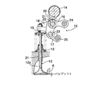
図1〜図3は本発明の一実施例を示すものであり、図1はブローバイガスおよびパージガス処理装置の全体構成を示す図、図2は高リフト状態での吸気弁の動弁装置を示す縦断側面図、図3は低リフト状態での吸気弁の動弁装置を示す縦断側面図である。 1 to 3 show an embodiment of the present invention, FIG. 1 is a diagram showing the overall configuration of a blow-by gas and purge gas processing device, and FIG. 2 shows a valve operating device for an intake valve in a high lift state. FIG. 3 is a longitudinal side view showing a valve operating device for an intake valve in a low lift state.
先ず図1において、エンジン本体5のシリンダヘッド6には、外部からの空気を浄化するエアクリーナ10と、該エアクリーナ10に下流側で接続される吸気チャンバ11とを備える吸気系9が接続されており、この吸気系9にスロットル弁が設けられることはない。
First, in FIG. 1, an
図2において、吸気弁12は弁ばね13で閉弁方向にばね付勢されつつシリンダヘッド6に開閉作動可能に配設されるものであり、この吸気弁12は、吸気側カムシャフト14によってリフト可変機構16を介して駆動され、該リフト可変機構15は、第1リンクアーム16と、第1リンクアーム16の下方に配置される第2リンクアーム17と、ロッカアーム18とを備える。
In FIG. 2, the
ロッカアーム18の一端部には、吸気弁12におけるステム12aの上端に上方から当接するタペットねじ19が進退位置を調節可能として螺合される。また吸気側カムシャフト14に設けられる動弁カム20に転がり接触するローラ21がアッパーピン22を介してロッカアーム18の他端部に軸支される。
A
第1リンクアーム16の一端部は、前記アッパーピン22を介して前記ロッカアーム18の他端部に回動可能に連結される。また第2リンクアーム17の一端部は、前記アッパーピン22よりも下方でロッカアーム18の他端部にロアピン23を介して回動可能に連結される。
One end of the
第1リンクアーム16の他端部は、シリンダヘッド6に固定したロッカシャフト24に回動可能に支承され、第2リンクアーム17の他端部は可動軸25で回動可能に支承される。この可動軸25は、図示しないアクチュエータによって上下に駆動される。
The other end of the
このようなリフト可変機構15において、可動軸25が上昇した状態では、吸気側カムシャフト14の動弁カム20でローラ21が押圧されると、ロッカシャフト24、アッパーピン22、ロアピン23および可動軸25を結ぶ四節リンクが変形してロッカアーム18が鎖線位置から実線位置へと下方に揺動し、タペットねじ19が吸気弁12のステム12aを押圧し、吸気弁12を高リフトで開弁する。
In such a
また可動軸25が、図3で示すように下降した状態では、吸気側カムシャフト14の動弁カム20でローラ21が押圧されると、前記四節リンクが変形してロッカアーム18が鎖線位置から実線位置へと下方に揺動し、タペットねじ19が吸気弁12のステム12aを押圧し、吸気弁12が低リフトで開弁する。
In the state where the
このようにして吸気弁12のリフト量をリフト可変機構15で変化させることができ、そのような吸気弁12のリフト量変化によって吸気量を調量することが可能であるので、吸気量を調量するためのスロットル弁を吸気系9に設けることが不要となる。
In this way, the lift amount of the
再び図1において、エンジン本体5のクランクケース7にはブリーザ室28が付設されており、そのブリーザ室28には第1吸引管路29の一端が接続される。また吸気系9においてエアクリーナ10および吸気チャンバ11間にはエンジン本体5をバイパスする第2吸引管路30の一端が接続されており、第1および第2吸引管路29,30の他端は、吸引側一方向弁31を介して第1ポンプ32の吸引側に接続される。すなわち第1ポンプ32は、エンジン本体5のクランクケース7からブローバイガスを吸引可能であるとともに、そのブローバイガス中に混入するように吸気系9からの新気を吸引することができる。
Referring again to FIG. 1, the
また第2吸引管路30の途中から分岐した分岐管路33がエンジン本体5の頂部に接続されており、エンジン本体5内には吸気系9からの新気を導入可能である。この実施例では第1吸引管路29の途中に流通量を制御する制御弁34が介設されるが、第2吸引管路30に制御弁が設けられていてもよく、また第1および第2吸引管路29,30にともに制御弁が設けられていてもよく、第1ポンプ32の吸引量全体を制御する制御弁が第1および第2吸引管路29,30の少なくとも一方に設けられていればよい。
A
第1ポンプ32は、排気側カムシャフト35に連動、連結されるとともにオイルで潤滑されるベーンポンプであり、エンジン本体5の各潤滑部にオイルを供給するためにエンジン本体5に装備されるオイルポンプ36からのオイルを導く油路37が、潤滑用として第1ポンプ32に接続される。
The
第1ポンプ32の吐出側は管路38を介して吸気系9の吸気チャンバ11に接続されるものであり、この管路38には、第1ポンプ32側から順に、吐出側一方向弁39と、オイルセパレータ40と、第2ポンプ41とが介設される。
The discharge side of the
第2ポンプ41は、キャニスタ42からのパージガスを第1ポンプ32で圧送されるブローバイガス中に混入せしめるためのものであり、燃料タンク43で蒸発してキャニスタ42で吸着された蒸発燃料が、第2ポンプ41およびキャニスタ42間に設けられるパージ制御弁44の開弁時に、キャニスタ42の底部から吸入した外気とともにパージガスとしてキャニスタ42から第2ポンプ41で吸引されることになる。
The
第2ポンプ41は、ブローバイガスを高速で流過させることによって発生する負圧を利用してパージガスを吸引すべく、第1ポンプ32で圧送されるブローバイガスを吸気系9に導く管路38の途中に配設されるジェットポンプである。
The
第1および第2ポンプ32,41間で管路38に介設されるオイルセパレータ40は、第1ポンプ32からのオイルを含むガスを邪魔板に衝突させて分離する第1セパレータ45と、第1セパレータ45からのガス中のオイルを分離する遠心分離式の第2セパレータ46とから成るものであり、第1および第2セパレータ45,46の底部は、開閉弁47,48を介して捕集タンク49に接続される。
The
すなわち開閉弁47,48の開弁によりオイルセパレータ40で分離されたオイルは捕集タンク49に貯留されることになり、この捕集タンク49に貯留されたオイルは、エンジン本体5の底部のオイルパン8に戻される。
That is, the oil separated by the
次にこの実施例の作用について説明すると、クランクケース7から吸引したブローバイガスは第1ポンプ32で吸気系9側に圧送され、キャニスタ42からのパージガスは、第1ポンプ32で圧送されるブローバイガス中に第2ポンプ41によって混入されるので、吸気系9に負圧が発生しないノンスロットル運転でも、ブローバイガスおよびパージガスを吸気系9に確実に導くことができ、しかもブローバイガスおよびパージガスを吸気系9に導く管路38を1つとしてラインの簡素化を図ることができる。
Next, the operation of this embodiment will be described. Blow-by gas sucked from the crankcase 7 is pumped to the
また第1ポンプ32が、オイルで潤滑されるベーンポンプであることにより、第1ポンプ32では、ベーンおよびポンプハウジング間のシール性を高めることができ、それによりブローバイガスの吸引・圧送効率を高めて大量のブローバイガスを吸引、圧送することができる。しかも第1ポンプ32には、エンジン本体5に装備されるオイルポンプ36からのオイルを導く油路37が潤滑用として接続されるものであり、エンジン本体5の各潤滑部にオイルを供給するためにエンジン本体5にもともと付設されているオイルポンプ36からのオイルを第1ポンプ32に供給するようにすることで、新たなオイル供給源を設けることを不要として簡素化を図ることが可能であり、しかもオイルポンプ36の元圧は充分に高いものであり、充分な量のオイルを第1ポンプ32に供給することができる。
Further, since the
それに加えて、第1ポンプ32は、排気側カムシャフト35に連動、連結されるものであり、吸気弁12の開閉制御によって吸気量を調量するようにしたノンスロットル運転を行う場合、吸気弁12側には吸気弁12の制御装置が配設されるため充分なスペースがなく、排気側カムシャフト35で第1ポンプ32を駆動するようにして第1ポンプ32の駆動系を配置するスペースを容易に確保することができる。
In addition, the
しかも第1ポンプ32の吸引側には、クランクケース7からのブローバイガスを導く第1吸引管路29と、吸気系9に一端が接続されるとともにエンジン本体5をバイパスする第2吸引管路30とが接続されるので、第1ポンプ32で充分な量のガス吸引ができるように流量調節を容易に行うことができる。すなわちエンジン本体5内でのブローバイガスの流通経路の流通抵抗はエンジン本体5の内部構造の違いによって変化するが、ブローバイガスおよび新気を第1ポンプ32で吸引することにより、エンジン本体5の構造の違いによっても第1ポンプ32で充分な量のガス吸引ができるように流量調節を容易に行うことが可能となり、ジェットポンプである第2ポンプ41で充分な負圧を発生させる量のガスを第1ポンプ32で圧送することが可能となる。
Moreover, on the suction side of the
一方、第2ポンプ41は、ブローバイガスを高速で流過させることによって発生する負圧を利用して前記パージガスを吸引すべく、第1ポンプ32で圧送されるブローバイガスを吸気系9に導く管路38の途中に配設されるジェットポンプであるので、構造が簡素であり、第2ポンプ41の軽量、コンパクト化を図るとともに第2ポンプ41の耐久信頼性を高めることができる。
On the other hand, the
また第1および第2ポンプ32,41間にはオイルセパレータ40が介設されており、第1ポンプ32でブローバイガス中に混入したオイルをオイルセパレータ40で分離することにより、第2ポンプ41での目詰まりや、吸気系9へのオイルの付着を防止し、全体システムの信頼性を高めることができる。
An
さらにオイルセパレータ40で捕集されるオイルを貯留する捕集タンク49からエンジン本体5のオイルパン8にオイルが戻されるので、エンジンオイルを無駄に消費することなく何度でも利用でき、効率がよい。
Further, since the oil is returned to the
以上、本発明の実施例を説明したが、本発明は上記実施例に限定されるものではなく、特許請求の範囲に記載された本発明を逸脱することなく種々の設計変更を行うことが可能である。 Although the embodiments of the present invention have been described above, the present invention is not limited to the above-described embodiments, and various design changes can be made without departing from the present invention described in the claims. It is.
たとえば上記実施例では、吸気弁12のリフト量を連続的に可変とすることで吸気量を調量するようにした可変動弁エンジンについて説明したが、ソレノイドで開閉駆動される吸気弁12の閉弁時期を可変とすることで吸気量を調量するようにした可変動弁エンジンについても本発明を適用可能である。
For example, in the above embodiment, the variable valve engine has been described in which the intake amount is adjusted by continuously changing the lift amount of the
5・・・エンジン本体
6・・・シリンダヘッド
7・・・クランクケース
8・・・オイルパン
9・・・吸気系
12・・・吸気弁
29・・・第1吸引管路
30・・・第2吸引管路
32・・・第1ポンプ
35・・・排気側カムシャフト
36・・・オイルポンプ
37・・・油路
40・・・オイルセパレータ
41・・・第2ポンプ
42・・・キャニスタ
49・・・捕集タンク
5 ...
Claims (8)
Priority Applications (2)
| Application Number | Priority Date | Filing Date | Title |
|---|---|---|---|
| JP2005055473A JP4511973B2 (en) | 2005-03-01 | 2005-03-01 | Blow-by gas and purge gas processing apparatus for variable valve engine |
| US11/364,547 US7281532B2 (en) | 2005-03-01 | 2006-03-01 | Blow-by gas and purge gas treating device in intake valve lift variable engine |
Applications Claiming Priority (1)
| Application Number | Priority Date | Filing Date | Title |
|---|---|---|---|
| JP2005055473A JP4511973B2 (en) | 2005-03-01 | 2005-03-01 | Blow-by gas and purge gas processing apparatus for variable valve engine |
Publications (2)
| Publication Number | Publication Date |
|---|---|
| JP2006242015A true JP2006242015A (en) | 2006-09-14 |
| JP4511973B2 JP4511973B2 (en) | 2010-07-28 |
Family
ID=37048683
Family Applications (1)
| Application Number | Title | Priority Date | Filing Date |
|---|---|---|---|
| JP2005055473A Expired - Fee Related JP4511973B2 (en) | 2005-03-01 | 2005-03-01 | Blow-by gas and purge gas processing apparatus for variable valve engine |
Country Status (1)
| Country | Link |
|---|---|
| JP (1) | JP4511973B2 (en) |
Citations (4)
| Publication number | Priority date | Publication date | Assignee | Title |
|---|---|---|---|---|
| JP2001164918A (en) * | 1999-12-06 | 2001-06-19 | Nissan Motor Co Ltd | Blow-by gas processing unit for gasoline engine |
| JP2002266663A (en) * | 2001-03-13 | 2002-09-18 | Nissan Motor Co Ltd | Intake control device for internal combustion engine |
| JP2003042014A (en) * | 2001-07-26 | 2003-02-13 | Toyota Motor Corp | Canister purge system |
| JP2004183592A (en) * | 2002-12-05 | 2004-07-02 | Nissan Motor Co Ltd | Engine fuel vapor treatment system |
-
2005
- 2005-03-01 JP JP2005055473A patent/JP4511973B2/en not_active Expired - Fee Related
Patent Citations (4)
| Publication number | Priority date | Publication date | Assignee | Title |
|---|---|---|---|---|
| JP2001164918A (en) * | 1999-12-06 | 2001-06-19 | Nissan Motor Co Ltd | Blow-by gas processing unit for gasoline engine |
| JP2002266663A (en) * | 2001-03-13 | 2002-09-18 | Nissan Motor Co Ltd | Intake control device for internal combustion engine |
| JP2003042014A (en) * | 2001-07-26 | 2003-02-13 | Toyota Motor Corp | Canister purge system |
| JP2004183592A (en) * | 2002-12-05 | 2004-07-02 | Nissan Motor Co Ltd | Engine fuel vapor treatment system |
Also Published As
| Publication number | Publication date |
|---|---|
| JP4511973B2 (en) | 2010-07-28 |
Similar Documents
| Publication | Publication Date | Title |
|---|---|---|
| US7281532B2 (en) | Blow-by gas and purge gas treating device in intake valve lift variable engine | |
| JP4720783B2 (en) | Supercharger lubrication device | |
| CN108661746B (en) | Engine oil supply device | |
| JP5964285B2 (en) | Internal combustion engine | |
| US7040306B2 (en) | Blowby gas ventilation system for an internal combustion engine, and method of using same | |
| CN101598048A (en) | engine breather | |
| JP6502596B2 (en) | Internal combustion engine | |
| CN103573474B (en) | Motor | |
| JP2008180134A (en) | Engine | |
| JP3689373B2 (en) | Overhead valve type 4-cycle engine | |
| JP4511973B2 (en) | Blow-by gas and purge gas processing apparatus for variable valve engine | |
| JP5478436B2 (en) | Engine blow-by gas recirculation system | |
| JP2016033340A (en) | Internal combustion engine | |
| JP2007046612A (en) | Internal combustion engine and its operation method | |
| JP2006242016A (en) | Blow-by gas and purge gas processing apparatus for variable valve engine | |
| JP4139247B2 (en) | 4-cycle engine lubrication system | |
| CN201354658Y (en) | engine lubricator | |
| JP2006316698A (en) | Oil mist processing equipment | |
| JP4560790B2 (en) | Membrane vaporizer | |
| JP2008175129A (en) | Crankcase ventilation equipment | |
| EP2527608A1 (en) | Internal combustion engine and motorcycle equipped with the engine | |
| JP6211455B2 (en) | Heating device for carburetor | |
| JP2007009746A (en) | Oil mist processing equipment | |
| CN201176887Y (en) | Engine lubricating device | |
| JP2013050060A (en) | Blowby gas treatment apparatus |
Legal Events
| Date | Code | Title | Description |
|---|---|---|---|
| A621 | Written request for application examination |
Effective date: 20071129 Free format text: JAPANESE INTERMEDIATE CODE: A621 |
|
| A131 | Notification of reasons for refusal |
Free format text: JAPANESE INTERMEDIATE CODE: A131 Effective date: 20100120 |
|
| A521 | Written amendment |
Free format text: JAPANESE INTERMEDIATE CODE: A523 Effective date: 20100323 |
|
| TRDD | Decision of grant or rejection written | ||
| A01 | Written decision to grant a patent or to grant a registration (utility model) |
Free format text: JAPANESE INTERMEDIATE CODE: A01 Effective date: 20100428 |
|
| A01 | Written decision to grant a patent or to grant a registration (utility model) |
Free format text: JAPANESE INTERMEDIATE CODE: A01 |
|
| A61 | First payment of annual fees (during grant procedure) |
Effective date: 20100507 Free format text: JAPANESE INTERMEDIATE CODE: A61 |
|
| FPAY | Renewal fee payment (prs date is renewal date of database) |
Free format text: PAYMENT UNTIL: 20130514 Year of fee payment: 3 |
|
| R150 | Certificate of patent (=grant) or registration of utility model |
Free format text: JAPANESE INTERMEDIATE CODE: R150 |
|
| LAPS | Cancellation because of no payment of annual fees |