JP2006242510A - Air conditioner - Google Patents
Air conditioner Download PDFInfo
- Publication number
- JP2006242510A JP2006242510A JP2005061105A JP2005061105A JP2006242510A JP 2006242510 A JP2006242510 A JP 2006242510A JP 2005061105 A JP2005061105 A JP 2005061105A JP 2005061105 A JP2005061105 A JP 2005061105A JP 2006242510 A JP2006242510 A JP 2006242510A
- Authority
- JP
- Japan
- Prior art keywords
- condenser
- air
- evaporator
- air conditioner
- flow path
- Prior art date
- Legal status (The legal status is an assumption and is not a legal conclusion. Google has not performed a legal analysis and makes no representation as to the accuracy of the status listed.)
- Pending
Links
Images


Landscapes
- Air-Conditioning Room Units, And Self-Contained Units In General (AREA)
Abstract
【課題】 局所的な冷房機能を有する空気調和機において、凝縮器を通った高温の空気を後方に排気することができる空気調和機を提供する。
【解決手段】 空気調和機は、背面パネル5を含む外カバー1と、外カバー11の内部において後側に配置された凝縮器11と、外カバー1の内部において後側に配置された蒸発器12とを備える。凝縮器11は、蒸発器12の下側に配置されている。凝縮器11の前側に凝縮器11ファンの空気の流路として、高さ方向に延びる縦流路が形成されている。凝縮器11と蒸発器12との間の空間の少なくとも一部を含むように、縦流路と連通して前後方向に延びる中間流路が形成されている。中間流路は、背面パネル5まで達するように形成されている。背面パネル5は、中間流路からの空気を外部に放出するように形成された排気部34を有する。
【選択図】 図2PROBLEM TO BE SOLVED: To provide an air conditioner capable of exhausting hot air passing through a condenser backward in an air conditioner having a local cooling function.
An air conditioner includes an outer cover (1) including a back panel (5), a condenser (11) arranged on the rear side inside the outer cover (11), and an evaporator arranged on the rear side inside the outer cover (1). 12. The condenser 11 is disposed below the evaporator 12. A longitudinal flow path extending in the height direction is formed on the front side of the condenser 11 as an air flow path of the condenser 11 fan. An intermediate flow path that communicates with the vertical flow path and extends in the front-rear direction is formed so as to include at least a part of the space between the condenser 11 and the evaporator 12. The intermediate flow path is formed to reach the back panel 5. The back panel 5 has an exhaust part 34 formed so as to discharge air from the intermediate flow path to the outside.
[Selection] Figure 2
Description
本発明は、空気調和機に関する。特に、除湿機能を有する空気調和機に関する。 The present invention relates to an air conditioner. In particular, the present invention relates to an air conditioner having a dehumidifying function.
空気調和機には、除湿を行なうために冷媒の凝縮器および蒸発器を備えるものがある。また、空気調和機には、容易に移動可能に形成され、除湿機能に加えて局所的な冷房機能を有するものがある。 Some air conditioners include a refrigerant condenser and an evaporator for dehumidification. Some air conditioners are easily movable and have a local cooling function in addition to a dehumidifying function.
図8に、特開2003−314855号公報に開示された空気調和機の概略構成図を示す。この空気調和機は、持ち運びができるように小型に形成されている。この空気調和機は、局所的な冷房と除湿との切換えを簡単な操作で行なうことができるように形成されている。 In FIG. 8, the schematic block diagram of the air conditioner disclosed by Unexamined-Japanese-Patent No. 2003-314855 is shown. This air conditioner is formed in a small size so that it can be carried. This air conditioner is formed so that switching between local cooling and dehumidification can be performed with a simple operation.
ハウジング50の内部には、それぞれの装置が配置されている。圧縮機57で圧縮された冷媒は、凝縮器51に送られて冷却されると共に凝縮される。凝縮器で凝縮された冷媒は、蒸発器に送られて蒸発器の内部で蒸発する。この後に、冷媒は圧縮機に戻される。
Each device is arranged inside the
蒸発器52は、内部で冷媒が蒸発するときの蒸発潜熱によって周囲の温度よりも低くなる。一方で、凝縮器51は、圧縮機57で圧縮された冷媒の温度が高いために周囲の温度よりも高くなる。蒸発器52を通った空気は低温になり、凝縮器51を通った空気は高温になる。
The
蒸発器52を通る空気の流路には、ダンパ装置59が配置されている。ダンパ装置59は、矢印73または矢印75に示すように、吹出口の切換が行なえるように形成されている。
A
この空気調和機において除湿を行なう場合には、ダンパ装置59を矢印73に示す向きに空気が流れるように設定する。第1送風機54によって、矢印71に示すように蒸発器52に室内の空気が送られる。室内の空気は、蒸発器52で行なわれる熱交換によって冷却される。蒸発器52の周りでは結露が生じる。結露して生じたドレン水は、ドレンタンク58に溜められる。
When dehumidification is performed in this air conditioner, the
蒸発器52を通った空気は、除湿されて乾燥している。蒸発器52を通った空気は、ダンパ装置59に送られる。ダンパ装置59においては向きが変更され、矢印73に示すように上側の吹出口から吹出される。
The air passing through the
また、室内の空気は、矢印72に示すように凝縮器51に送られる。凝縮器51においては、熱交換が行なわれて、空気の温度が上昇する。凝縮器51を通った空気は、第2送風機53によって、矢印74に示すように空気調和機の上側の吹出口から吹出される。
Further, the indoor air is sent to the condenser 51 as indicated by an
空気調和機の上方への吹出口においては、凝縮器からの高温の空気と蒸発器からの低温の空気とが混合されて吹出される。吹出される空気は、湿分の少ない空気になっている。除去された湿分は、ドレンタンクに溜められて、適宜廃棄される。 At the upper outlet of the air conditioner, the hot air from the condenser and the cold air from the evaporator are mixed and blown out. The air blown out is air with low moisture. The removed moisture is stored in a drain tank and discarded as appropriate.
この空気調和機において局所的な冷房を行なう場合、すなわち、スポットクーラとして用いる場合には、ダンパ装置59によって矢印75に示す向きに空気の経路を変更する。矢印75に示す流れの空気は、蒸発器52を通った空気であるために低温である。この低温の空気は、空気調和機の前側の吹出口から吹出される。凝縮器51を通った高温の空気は、矢印74に示すように、上側の吹出口から吹出され、低温の空気と分離される。このように、局所的な冷房を行なう空気調和機として用いることができる。
上記の特開2003−314855号公報に開示された空気調和機においては、1つの空気調和機でありながら、除湿と局所的な冷房とを行なうことができる。さらに、持ち運びが可能であり、好みの場所で手軽に使うことができる。 In the air conditioner disclosed in the above Japanese Patent Application Laid-Open No. 2003-314855, it is possible to perform dehumidification and local cooling while being one air conditioner. Furthermore, it is portable and can be used easily at your preferred location.
しかしながら、上記の公報に開示された空気調和機において、局所的な冷房機として用いる場合に、凝縮器を通った高温の空気は空気調和機の上方へ排気される。このため、局所的な冷房機として用いているにも関わらず、この暖かい空気に人があたってしまうという問題があった。たとえば、空気調和機の上面に配置されている操作部を操作する際に、上面の吹出口から吹出される暖かい空気にあたってしまうという問題があった。 However, in the air conditioner disclosed in the above publication, when used as a local air conditioner, high-temperature air that has passed through the condenser is exhausted above the air conditioner. For this reason, there is a problem that people are exposed to this warm air even though it is used as a local air conditioner. For example, when operating the operation part arrange | positioned at the upper surface of an air conditioner, there existed a problem that it would hit the warm air which blows off from the blower outlet of an upper surface.
本発明は、局所的な冷房機能を有する空気調和機において、凝縮器を通った高温の空気を後方に排気することができる空気調和機を提供することを目的とする。 An object of the present invention is to provide an air conditioner capable of exhausting high-temperature air that has passed through a condenser backward in an air conditioner having a local cooling function.
本発明に基づく空気調和機は、背面パネルを含む外カバーと、上記外カバーの内部において後側に配置され、加圧された冷媒を冷却するための凝縮器と、上記外カバーの内部において後側に配置され、上記冷媒を内部で蒸発させるための蒸発器と、上記凝縮器の前側に配置され、空気を上側に向かって送るための凝縮器ファンと、上記蒸発器の前側に配置され、空気を前側に向かって送るための蒸発器ファンとを備える。上記凝縮器は、上記蒸発器の下側に配置されている。上記凝縮器の前側に上記凝縮器ファンの空気の流路として、高さ方向に延びる縦流路が形成されている。上記凝縮器と上記蒸発器との間の空間の少なくとも一部を含むように、上記縦流路と連通して前後方向に延びる中間流路が形成されている。上記中間流路は、背面パネルまで達するように形成されている。上記背面パネルは、上記中間流路からの空気を外部に放出するように形成された排気部を有する。この構成を採用することにより、上記凝縮器を通った高温の空気を後方に排気できる空気調和機を提供することができる。 An air conditioner according to the present invention includes an outer cover including a rear panel, a condenser disposed on the rear side inside the outer cover, for cooling the pressurized refrigerant, and a rear part inside the outer cover. Arranged on the side, an evaporator for evaporating the refrigerant inside, a condenser fan for sending air upward, arranged on the front side of the condenser, and arranged on the front side of the evaporator, An evaporator fan for sending air toward the front side. The condenser is disposed below the evaporator. A longitudinal flow path extending in the height direction is formed as an air flow path of the condenser fan on the front side of the condenser. An intermediate flow path that communicates with the longitudinal flow path and extends in the front-rear direction is formed so as to include at least a part of the space between the condenser and the evaporator. The intermediate flow path is formed to reach the back panel. The back panel has an exhaust part formed to discharge air from the intermediate flow path to the outside. By adopting this configuration, it is possible to provide an air conditioner that can exhaust high-temperature air that has passed through the condenser to the rear.
上記発明において好ましくは、上記排気部は複数の風向板を含み、上記風向板は、水平方向に延びるように形成され、上記風向板は、外側が低くなるように傾斜して配置されている。この構成を採用することにより、上記排気部から下側に向かって排気を行なうことができる。 Preferably, in the above invention, the exhaust section includes a plurality of wind direction plates, the wind direction plates are formed so as to extend in a horizontal direction, and the wind direction plates are disposed so as to be inclined so that the outside becomes lower. By adopting this configuration, exhaust can be performed downward from the exhaust section.
本発明によれば、局所的な冷房機能を有する空気調和機において、凝縮器を通った高温の空気を後方に排気することができる空気調和機を提供することができる。 ADVANTAGE OF THE INVENTION According to this invention, in the air conditioner which has a local cooling function, the air conditioner which can exhaust the high temperature air which passed the condenser back can be provided.
図1から図7を参照して、本発明に基づく実施の形態における空気調和機について説明する。本実施の形態における空気調和機は、除湿機能と局所的な冷房機能とを有する。また、持ち運んだり押したりすることにより移動可能に形成されている。 With reference to FIGS. 1-7, the air conditioner in embodiment based on this invention is demonstrated. The air conditioner in the present embodiment has a dehumidifying function and a local cooling function. Moreover, it is formed so as to be movable by being carried or pushed.
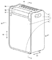
図1は、空気調和機を前側から見たときの斜視図である。矢印61は、空気調和機の前後方向(奥行き方向)を示し、矢印62は、空気調和機の高さ方向を示す。空気調和機は、外カバー1を備える。外カバー1は、前面パネル2、上面パネル3、側面パネル4および底面パネル8を含む。
FIG. 1 is a perspective view of the air conditioner as viewed from the front side. An
前面パネル2は、空気調和機の前側のほぼ全体の部分を覆うように形成されている。前面パネル2は、前側に向かって取外しが可能なように形成されている。側面パネル4は、空気調和機の側面に配置されている。側面パネル4の上部には、持ち運びを行なうときに手を引掛けるための取っ手部が形成されている。すなわち、本実施の形態における空気調和機は、取っ手部に手を引掛けて一人で持ち運びができるように形成されている。また、底面パネル8の下側には、人が空気調和機を押して移動できるように車輪が配置されている。上面パネル3は、空気調和機の上面に配置されている。上面パネル3には、操作部41が配置されている。操作部41には、複数のボタンが形成されている。
The
外カバー1の前側の上部には、除湿された空気または冷却された空気を吹出すための吹出口31が形成されている。本実施の形態における空気調和機には、吹出口31に2個のルーバ6a,6bが配置されている。
A
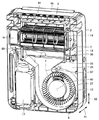
図2に、図1におけるII−II線に関する破断図を示す。矢印61に示す方向は、空気調和機の前後方向である。矢印62に示す方向は、空気調和機の高さ方向である。
FIG. 2 is a cutaway view taken along line II-II in FIG. The direction shown by the
本実施の形態における空気調和機は、外カバー1の内部において、後側に配置された凝縮器11を備える。また、空気調和機は、外カバー1の内部において、後側に配置された蒸発器12を備える。凝縮器11と蒸発器12とは、空気調和機の高さ方向に配列するように配置されている。本実施の形態においては、凝縮器11は、蒸発器12の下側に配置されている。凝縮器11と蒸発器12とは、離れて配置されている。
The air conditioner in the present embodiment includes a
凝縮器11は、圧縮機によって加圧された冷媒を内部で冷却するための熱交換器である。蒸発器12は、冷媒を気化させて周りの空気との熱交換を行なうための熱交換器である。
The
外カバー1は、空気調和機の背面に配置された背面パネル5を含む。背面パネル5は、空気調和機の後側の領域のほぼ全体を覆うように配置されている。
The
図3に、本実施の形態における空気調和機を後側から見たときの斜視図を示す。背面パネル5は、板状に形成されている。背面パネル5は、上部に複数の吸気口が形成された蒸発器吸気部33を有する。また、背面パネル5は、下部に複数の吸気口が形成された凝縮器吸気部32を有する。凝縮器吸気部32と蒸発器吸気部33との間には、排気口としての排気部34が形成されている。空気調和機の背面の下端には、電源コード21が配置されている。
In FIG. 3, the perspective view when the air conditioner in this Embodiment is seen from the rear side is shown. The
図2を参照して、凝縮器吸気部32は、凝縮器11に向かって空気が進入するように形成されている。蒸発器吸気部33は、蒸発器12に向かって空気が進入するように形成されている。
Referring to FIG. 2, the
本実施の形態においては、凝縮器11および蒸発器12は、それぞれが背面パネル5に近接して配置されている。凝縮器吸気部32および蒸発器吸気部33は、背面から見たときに、それぞれの熱交換器の大きさとほぼ同じ大きさになるように形成されている。
In the present embodiment, each of the
凝縮器11の前側には、凝縮器ファン13が配置されている。凝縮器ファン13の内部には、凝縮器ファンモータ15が配置されている。凝縮器ファン13は、いわゆるシロッコファンである。凝縮器ファン13は、回転することにより矢印63に示す方向のうち、上側に向かって空気を送るように形成されている。
A
蒸発器12の前側には、蒸発器ファン14が配置されている。蒸発器ファン14は、蒸発器ファン14の外側に配置された蒸発器ファンモータに接続されている。蒸発器ファン14は、いわゆるクロスフローファンである。蒸発器ファン14は、回転軸46を中心に回転するように形成されている。蒸発器ファン14は、矢印66に示すように、蒸発器12からの空気を前側に向けて送るように形成されている。
An
蒸発器ファン14の下側には、蒸発器ファン14を囲むように第1のケーシング25が配置されている。第1のケーシング25は、板状に形成されている。第1のケーシング25は、蒸発器ファン14の形状に沿って形成されている。第1のケーシング25は、空気調和機の前後方向および幅方向に延びるように形成されている。第1のケーシング25は、矢印66に示すように、蒸発器ファン14からの空気を空気調和機の前側の上部の吹出口31に導くことができるように形成されている。
A
第1のケーシング25の下側には、間隔を空けて第2のケーシング26が配置されている。第2のケーシング26は、板状に形成されている。第2のケーシング26は、第1のケーシング25に沿う部分と下側に向かって延びる部分とを有する。第1のケーシング25に沿う部分は、空気調和機の前後方向および幅方向に延びるように形成されている。下側に向かって延びる部分は、空気調和機の高さ方向および幅方向に延びるように形成されている。
A
凝縮器11の前側には、凝縮器11と第2のケーシング26との間の空間の一部を含むように高さ方向に延びる縦流路が形成されている。すなわち、矢印63に示すように、高さ方向に空気が流れるように流路が形成されている。
A longitudinal channel extending in the height direction is formed on the front side of the
本実施の形態における空気調和機には、凝縮器11と蒸発器12との間の空間の一部および第1のケーシング25と第2のケーシング26との間の空間の一部を含むように前後方向に延びる中間流路が形成されている。中間流路は、矢印64に示すように、空気調和機の前後方向に空気が流れるように形成されている。中間流路は、背面パネル5まで達するように形成されている。また、中間流路は、上記の縦流路と連通するように形成されている。
The air conditioner in the present embodiment includes a part of the space between the
図4に、本実施の形態における排気部の部分の拡大破断図を示す。排気部34は、中間流路からの空気を外部に放出するように形成されている。排気部34は、背面パネル5に開口が形成され、この開口に複数の風向板23が配置された構成を有する。風向板23は、水平方向に延びるように形成されている。風向板23は、外側が低くなるように傾斜して配置されている。
FIG. 4 shows an enlarged cutaway view of the exhaust portion in the present embodiment. The
図2を参照して、中間流路と縦流路とが交わる領域には、ダンパ7が配置されている。本実施の形態におけるダンパ7は、1/4円状の断面形状を有する。ダンパ7は、1/4円の中心を回動軸として矢印69に示すように回動可能に形成されている。本実施の形態においては、ダンパ7は、第1のケーシング25との間に隙間を有するように配置されている。
With reference to FIG. 2, a
第1のケーシング25の前側の端部には開口部35が形成されている。開口部35は、蒸発器ファン14から吹出口31に向かう空気の流路に対して中間流路が合流するように形成されている。開口部35は、中間流路の端部に位置するように形成されている。
An
第1のケーシング25の下側において、開口部35の近傍には、空気中の除菌を行なうためのイオンを発生するイオン発生器22が配置されている。本実施の形態においては、空気調和機の幅方向の両端に2つのイオン発生器22が配置されている。本実施の形態におけるイオン発生器22は、中間流路の端部に配置されている。
On the lower side of the
蒸発器12の下側には、蒸発器12に結露した結露水(ドレン水)を集めるための結露皿19が配置されている。結露皿19は、蒸発器12の下部の形状に沿うように断面形状がコの字形に形成されている。第2のケーシング26の前側には、除湿を行なったときのドレン水を溜めるためのドレンタンク18が配置されている。ドレンタンク18は、外カバー1の内部において前側に配置されている。
A
図5に、図1におけるIV−IV線に関する破断図を示す。蒸発器ファン14は、ほぼ円柱状に形成され、回転軸が空気調和機の幅方向と平行に配置されている。蒸発器ファン14の側方には蒸発器ファンモータ16が配置されている。
FIG. 5 is a cutaway view taken along line IV-IV in FIG. The
凝縮器ファン13は、ほぼ円柱状に形成され、回転軸45が、空気調和機の前後方向に延びるように配置されている。凝縮器ファン13は、凝縮器ファン13が回転することにより、矢印67に示すように、ダンパ7に向かって空気を流すことができるように形成されている。
The
ダンパ7は、空気調和機の幅方向に延びるように形成されている。ダンパ7は、矢印69に示すように、空気調和機の幅方向に平行な軸を回転軸として回動するように形成されている。
The
ダンパ7の側方には、ダンパ7を回動するためのステップモータ20が配置されている。ステップモータ20は、任意の位置でダンパ7を停止できるように形成されている。凝縮器ファン13の周りには、凝縮器ファン13の形状に沿って第3のケーシング27が配置されている。第3のケーシング27は、板状に形成されている。
A
凝縮器ファン13の側方には、冷媒を圧縮するための圧縮機17が配置されている。圧縮機17は、外カバー1の内部において底面パネル8に固定されている。
A
図6に、背面パネルを取外して、さらに、結露皿を取外したときの斜視図を示す。図6は、後側から見たときの斜視図である。本実施の形態においては、結露皿19と第1のケーシング25とは一体的に形成されている。開口部35は、第1のケーシング25の先端部に、幅方向に延びるように形成されている。
FIG. 6 shows a perspective view when the back panel is removed and the dew condensation tray is further removed. FIG. 6 is a perspective view when viewed from the rear side. In the present embodiment, the
凝縮器11および蒸発器12は、複数のフィンおよび冷媒が通るための配管を含む。本実施の形態においては、凝縮器11および蒸発器12は、それぞれが直方体状に形成されている。
The
結露皿19は、空気調和機の幅方向に延びる部分と空気調和機の前側に向かって延びる部分とを有する。前側に向かって延びる部分の端部には、ドレン水の排出部36が形成されている。排出部36は、ドレンタンクに接続される。
The
図2および図4を参照して、本実施の形態における空気調和機を局所的な冷房機として用いる場合には、空気を遮断する面が前側に位置するようにダンパ7を配置する。すなわち、中間流路において後側に空気が流れるようにダンパ7を配置する。ダンパ7の回動には、ステップモータが用いられる。
Referring to FIGS. 2 and 4, when the air conditioner in the present embodiment is used as a local air conditioner,
図2、図4および図5を参照して、凝縮器ファンモータ15が駆動することにより、凝縮器ファン13が回転する。凝縮器ファン13が回転することにより、外側から凝縮器吸気部32を通って凝縮器11に空気が進入する。凝縮器11を通った空気は、熱交換が行なわれて吸入する空気よりも高温になる。
With reference to FIGS. 2, 4, and 5, the
凝縮器11を通った空気は、凝縮器11と第2のケーシング26とで挟まれる空間の一部を含む縦流路において上側に向かって流れる。この後に、空気は、ダンパ7の向きに沿って空気調和機の後側に向きを変えて、中間流路を流れて排気部34から排気される。このように、凝縮器11を通った空気は、矢印65に示すように縦流路および中間流路を通って、後側に配置された排気部34から排気される。
The air that has passed through the
蒸発器ファンモータ16が駆動することにより、蒸発器ファン14が回転する。蒸発器ファン14が回転することにより、矢印66に示すように蒸発器吸気部33を通って進入した空気が吹出口31に向かって吹出される。蒸発器吸気部33を通って吸気された空気は、蒸発器12を通ることにより冷却され、吸入する空気よりも低温になる。この後に前側の吹出口31から吹出される。吹出口31から吹出される際には、ルーバ6a,6bの向きに沿って低温の空気が吹出される。
When the
また、吸気された空気は、蒸発器12で結露して湿分が除去される。吸入される空気は、蒸発器12を通ることにより乾燥した空気になる。除去された湿分は、結露水として結露皿19に落下して、ドレンタンク18に導かれる。
The sucked air is condensed by the
一方で、圧縮機17が駆動することにより、冷媒が圧縮機によって圧縮され、凝縮器11に送られる。凝縮器11において、凝縮器吸気部32から吸気された空気によって熱交換が行なわれて冷媒が冷却される。凝縮器11においては、冷媒が冷却されて凝縮する。凝縮器11を出た冷媒は蒸発器12に向かう。蒸発器12においては、冷媒の一部が蒸発する。冷媒が蒸発するときの蒸発潜熱によって蒸発器12は低温になる。蒸発器12を通った冷媒は、再び圧縮機17に戻される。
On the other hand, when the
このように、本実施の形態における空気調和機は、凝縮器11を通った高温の空気が、後側に排出される。このため、高温の空気が上側から吹出して、上面パネルに配置された操作部を操作する際に高温の空気が使用者にあたってしまうことを防止できる。また、高温の空気は後側に排気され、前側に低温の空気が吹出されるため、局所的な冷房を行なう冷房機としての機能を十分に発揮することができる。
Thus, in the air conditioner in the present embodiment, the high-temperature air that has passed through the
また、図4を参照して、本実施の形態においては、排気部34に複数の風向板23が配置され、風向板23は、外側が低くなるように形成されている。この構成を採用することにより、空気を下側に向かって排気することができ、使用者に高温の空気があたってしまうことをより確実に防止できる。たとえば、空気調和機を室内の側壁の近傍に配置したときに、排気された高温の空気が側壁にあたって上側に向かって流れ、使用者にあたってしまうことを防止できる。
Referring to FIG. 4, in the present embodiment, a plurality of
図7に、本実施の形態における空調機を除湿のみを行なう除湿機として使用する場合の破断図を示す。図7に示す破断図は、図1におけるII−II線に対応する破断図である。 In FIG. 7, the fracture | rupture figure at the time of using the air conditioner in this Embodiment as a dehumidifier which performs only dehumidification is shown. The fracture view shown in FIG. 7 is a fracture view corresponding to the line II-II in FIG.
除湿機として使用する場合には、局所的な冷房機として使用する場合と比較して、ダンパ7の位置が異なる。ダンパ7は、空気の流れを遮断する部分が、空気調和機の後側に配置される。すなわち、ダンパ7は、縦流路を通った空気がダンパ7によって中間流路の前側に向かって流れるように配置されている。
When used as a dehumidifier, the position of the
凝縮器ファン13が回転することにより、縦流路において上側に空気が流れる。上側に向かって流れる空気は、ダンパ7の形状に沿って前側に向きを変える。空気は、中間流路のうち第1のケーシングと第2のケーシングとに挟まれる空間を空気調和機の前側に向かって流れる。この後に、第1のケーシング25の開口部35を通って、凝縮器ファン13からの空気と合流する。この後に、吹出口31から吹出される。
As the
凝縮器11を通った高温の空気は、矢印68に示すように、縦流路および中間流路の前側の部分を通って、蒸発器12からの低温の空気と合流した後に吹出口31から吹出される。凝縮器11を通った空気は除湿されているため、吹出口31から乾燥した空気を吹出すことができる。除湿機として使用する場合には、高温の空気と低温の空気とが混合され、室温よりも僅かに高い温度になった状態で空気を吹出すことができる。
The hot air that has passed through the
冷媒が圧縮機で圧縮され、凝縮器および蒸発器を通って圧縮機に戻ることは、局所的な冷房機として機能する場合と同様である。 The refrigerant is compressed by the compressor and returns to the compressor through the condenser and the evaporator as in the case of functioning as a local air conditioner.
中間流路において、イオン発生器22を駆動することにより、空気を電離してイオンを発生することができる。生じたイオンは、中間流路を通る空気に含まれた状態で、吹出口31から吹出される。イオン発生器22を駆動することにより、吹出す空気に除菌機能を備えることができる。
By driving the
図2、図5および図7を参照して、本実施の形態における空気調和機は、凝縮器11および蒸発器12が、外カバー1の内部において後側に配置され、凝縮器11と蒸発器12とが高さ方向に配列するように配置されている。この構成を採用することにより、空気の流路を大きくすることができ、除湿機能および冷房機能を向上させることができる。特に、空気調和機の幅方向に流路を確保することができ、通風抵抗を小さくすることができる。または、同じ除湿性能および同じ冷房機能を有する空気調和機を形成した場合に、従来の技術における空気調和機よりも小型化を図ることができる。
2, 5 and 7, in the air conditioner of the present embodiment, a
さらに、凝縮器11と蒸発器12とを高さ方向に配列して配置することにより、それぞれの熱交換器に対する空気の吸込み口を大きくすることができる。この結果、それぞれの熱交換器を通る風量を多くすることができる。また、それぞれの熱交換器の表面積を大きくすることができる。したがって、除湿機能および冷房機能ともにその性能を向上させることができる。また、凝縮器11と凝縮器ファン13とを近接した位置に配置することができる。また、蒸発器12と蒸発器ファン14とを近接した位置に配置することができる。凝縮器11および蒸発器12は、外カバー1の内部の空間を大きくするために背面パネル5に近接して配置することが好ましい。
Furthermore, by arranging the
また、従来の技術においては、蒸発器ファンとして、内側にモータが配置されたシロッコファンを採用していたが、外カバー1の内部の空間に余裕が生じて蒸発器ファンにモータがファンの外側に配置されたクロスフローファンを採用することができる。この結果、従来の技術における空気調和機とほぼ同じ大きさでありながら、蒸発器ファンの駆動音を小さくすることができ、空気調和機を静かに運転することができる。
In the prior art, a sirocco fan in which a motor is disposed on the inside is used as an evaporator fan. However, there is a margin in the space inside the
さらに、本発明における空気調和機は、凝縮器と蒸発器とが高さ方向に配列して配置されているため、組立やメインテナンス時などの分解を容易に行なうことができる。従来の技術における空気調和機は、中央部分に凝縮器および蒸発器が集まって配置されているために、組立手順が複雑であったり各装置の配置に時間がかかったりした。しかし、本発明における空気調和機は、容易に組立および分解を行なうことができて、作業性が向上する。 Furthermore, since the condenser and the evaporator are arranged in the height direction, the air conditioner according to the present invention can be easily disassembled during assembly or maintenance. In the conventional air conditioner, since the condenser and the evaporator are arranged in the central portion, the assembling procedure is complicated and it takes time to arrange each device. However, the air conditioner according to the present invention can be easily assembled and disassembled, and the workability is improved.
本実施の形態においては、凝縮器11の前側に、凝縮器ファン13の空気の流路として高さ方向に延びる縦流路が形成されている。また、縦流路と連通して、凝縮器11と蒸発器12とに挟まれる空間を含むように、前後方向に延びる中間流路が形成されている。縦流路と中間流路とが交わる領域にはダンパ7が配置されている。この構成を採用することにより、ダンパ7を回動するのみで除湿機能と局所的な冷房機能とを容易に切換えることができる。
In the present embodiment, a longitudinal flow path extending in the height direction is formed on the front side of the
本実施の形態においては、外カバー1の前側に吹出口31が形成され、蒸発器ファン14からの空気の流路と、中間流路とが合流して吹出口31に向かうように形成されている。この構成を採用することにより、除湿機として用いる場合および局所的な冷房機として用いる場合の両方において、同じ吹出口から、除湿された空気または低温の空気を吹出すことができる。
In the present embodiment, a
本実施の形態においては、ダンパ7を回動するためのステップモータ20を備え、ダンパは1/4円状の断面形状を有して回動可能なように形成されている。この構成を採用することにより、中間流路において、凝縮器を通った高温の空気を中間流路の前側または後側に流すためのダンパを容易に形成することができる。
In the present embodiment, a
ダンパを駆動する手段としてモータを用いることにより、自動運転が可能になる。または、ボタン操作で冷房機能と除湿機能とを切替ることができる。特に、ダンパを駆動する手段として、ステップモータを用いることにより、ダンパの回動角度を任意の角度で停止させることができ、局所的な冷房機として用いる場合に吹出口からの温度を調整することができる。 Automatic operation is possible by using a motor as means for driving the damper. Or a cooling function and a dehumidification function can be switched by button operation. In particular, by using a step motor as a means for driving the damper, the rotation angle of the damper can be stopped at an arbitrary angle, and when used as a local cooling device, the temperature from the outlet is adjusted. Can do.
本実施の形態においては、上側に蒸発器を配置して、下側に凝縮器を配置したが、この形態に限られず、蒸発器を下側に配置して、凝縮器を上側に配置してもかまわない。 In the present embodiment, the evaporator is disposed on the upper side and the condenser is disposed on the lower side. However, the present invention is not limited to this, and the evaporator is disposed on the lower side and the condenser is disposed on the upper side. It doesn't matter.
また、本実施の形態においては、ダンパとして、断面形状が1/4円状のダンパを用いたが、この形態に限られず、前側と後側に流れを変更できるように形成されていれば、任意の形状のダンパを採用することができる。 Further, in the present embodiment, a damper having a quarter-circular cross section is used as the damper, but the present invention is not limited to this form, and if the flow can be changed to the front side and the rear side, Any shape of damper can be employed.
本実施の形態においては、局所的な冷房機能を備える除湿機を例に取上げて説明したが、この形態に限られず、局所的な冷房機能を有する空気調和機に適用することができる。たとえば、可動不能なダンパを配置した局所的な冷房機能のみを有する空気調和機に本願発明を適用することができる。 In the present embodiment, the dehumidifier having a local cooling function has been described as an example. However, the present invention is not limited to this embodiment, and the present invention can be applied to an air conditioner having a local cooling function. For example, the present invention can be applied to an air conditioner having only a local cooling function in which a non-movable damper is arranged.
上記の実施の形態に係るそれぞれの図面において、同一または相当する部分には、同一の符号を付している。 In the respective drawings according to the above-described embodiments, the same or corresponding parts are denoted by the same reference numerals.
なお、今回開示した上記実施の形態はすべての点で例示であって制限的なものではない。本発明の範囲は上記した説明ではなくて特許請求の範囲によって示され、特許請求の範囲と均等の意味および範囲内でのすべての変更を含むものである。 In addition, the said embodiment disclosed this time is an illustration in all the points, Comprising: It is not restrictive. The scope of the present invention is defined by the terms of the claims, rather than the description above, and includes all modifications within the scope and meaning equivalent to the terms of the claims.
1 外カバー、2 前面パネル、3 上面パネル、4 側面パネル、5 背面パネル、6a,6b ルーバ、7 ダンパ、8 底面パネル、11 凝縮器、12 蒸発器、13 凝縮器ファン、14 蒸発器ファン、15 凝縮器ファンモータ、16 蒸発器ファンモータ、17 圧縮機、18 ドレンタンク、19 結露皿、20 ステップモータ、21 電源コード、22 イオン発生器、23 風向板、25 第1のケーシング、26 第2のケーシング、27 第3のケーシング、31 吹出口、32 凝縮器吸気部、33 蒸発器吸気部、34 排気部、35 開口部、36 排出部、41 操作部、45,46 回転軸、50 ハウジング、51 凝縮器、52 蒸発器、53 第2送風機、54 第1送風機、57 圧縮機、58 ドレンタンク、59 ダンパ装置、61〜69,71〜75 矢印。 1 outer cover, 2 front panel, 3 top panel, 4 side panel, 5 back panel, 6a, 6b louver, 7 damper, 8 bottom panel, 11 condenser, 12 evaporator, 13 condenser fan, 14 evaporator fan, 15 Condenser fan motor, 16 Evaporator fan motor, 17 Compressor, 18 Drain tank, 19 Condensation dish, 20 Step motor, 21 Power cord, 22 Ion generator, 23 Wind direction plate, 25 First casing, 26 Second Casing, 27 third casing, 31 air outlet, 32 condenser intake section, 33 evaporator intake section, 34 exhaust section, 35 opening section, 36 discharge section, 41 operation section, 45, 46 rotating shaft, 50 housing, 51 Condenser, 52 Evaporator, 53 Second Blower, 54 First Blower, 57 Compressor, 58 Drain Tank, 59 Lymph system, 61~69,71~75 arrow.
Claims (2)
前記外カバーの内部において後側に配置され、加圧された冷媒を冷却するための凝縮器と、
前記外カバーの内部において後側に配置され、前記冷媒を内部で蒸発させるための蒸発器と、
前記凝縮器の前側に配置され、空気を上側に向かって送るための凝縮器ファンと、
前記蒸発器の前側に配置され、空気を前側に向かって送るための蒸発器ファンと
を備え、
前記凝縮器は、前記蒸発器の下側に配置され、
前記凝縮器の前側に前記凝縮器ファンの空気の流路として、高さ方向に延びる縦流路が形成され、
前記凝縮器と前記蒸発器との間の空間の少なくとも一部を含むように、前記縦流路と連通して前後方向に延びる中間流路が形成され、
前記中間流路は、背面パネルまで達するように形成され、
前記背面パネルは、前記中間流路からの空気を外部に放出するように形成された排気部を有する、空気調和機。 An outer cover including a back panel;
A condenser disposed on the rear side of the outer cover and for cooling the pressurized refrigerant;
An evaporator disposed on the rear side of the outer cover for evaporating the refrigerant inside;
A condenser fan disposed on the front side of the condenser and for sending air upward;
An evaporator fan disposed on the front side of the evaporator and for sending air toward the front side;
The condenser is located below the evaporator;
As the air flow path of the condenser fan on the front side of the condenser, a vertical flow path extending in the height direction is formed,
An intermediate flow path that communicates with the longitudinal flow path and extends in the front-rear direction is formed so as to include at least part of the space between the condenser and the evaporator,
The intermediate flow path is formed to reach the back panel,
The said back panel is an air conditioner which has an exhaust part formed so that the air from the said intermediate flow path might be discharge | released outside.
前記風向板は、水平方向に延びるように形成され、
前記風向板は、外側が低くなるように傾斜して配置された、請求項1に記載の空気調和機。 The exhaust part includes a plurality of wind direction plates,
The wind direction plate is formed to extend in a horizontal direction,
The air conditioner according to claim 1, wherein the wind direction plate is disposed so as to be inclined so that an outer side is lowered.
Priority Applications (1)
| Application Number | Priority Date | Filing Date | Title |
|---|---|---|---|
| JP2005061105A JP2006242510A (en) | 2005-03-04 | 2005-03-04 | Air conditioner |
Applications Claiming Priority (1)
| Application Number | Priority Date | Filing Date | Title |
|---|---|---|---|
| JP2005061105A JP2006242510A (en) | 2005-03-04 | 2005-03-04 | Air conditioner |
Publications (1)
| Publication Number | Publication Date |
|---|---|
| JP2006242510A true JP2006242510A (en) | 2006-09-14 |
Family
ID=37049101
Family Applications (1)
| Application Number | Title | Priority Date | Filing Date |
|---|---|---|---|
| JP2005061105A Pending JP2006242510A (en) | 2005-03-04 | 2005-03-04 | Air conditioner |
Country Status (1)
| Country | Link |
|---|---|
| JP (1) | JP2006242510A (en) |
Cited By (3)
| Publication number | Priority date | Publication date | Assignee | Title |
|---|---|---|---|---|
| WO2015111245A1 (en) * | 2014-01-23 | 2015-07-30 | シャープ株式会社 | Air conditioner |
| CN109323335A (en) * | 2018-11-02 | 2019-02-12 | 青岛海尔空调器有限总公司 | An indoor unit of an air conditioner and an air conditioner |
| CN109323336A (en) * | 2018-11-02 | 2019-02-12 | 青岛海尔空调器有限总公司 | An indoor unit of an air conditioner and an air conditioner |
Citations (4)
| Publication number | Priority date | Publication date | Assignee | Title |
|---|---|---|---|---|
| JPS526555U (en) * | 1975-07-01 | 1977-01-18 | ||
| JPS62176628U (en) * | 1986-04-28 | 1987-11-10 | ||
| JPH0669621U (en) * | 1992-09-04 | 1994-09-30 | ウエツトマスター株式会社 | Spot Cooler |
| JP2002071165A (en) * | 2000-08-30 | 2002-03-08 | Toshiba Kyaria Kk | Air conditioner |
-
2005
- 2005-03-04 JP JP2005061105A patent/JP2006242510A/en active Pending
Patent Citations (4)
| Publication number | Priority date | Publication date | Assignee | Title |
|---|---|---|---|---|
| JPS526555U (en) * | 1975-07-01 | 1977-01-18 | ||
| JPS62176628U (en) * | 1986-04-28 | 1987-11-10 | ||
| JPH0669621U (en) * | 1992-09-04 | 1994-09-30 | ウエツトマスター株式会社 | Spot Cooler |
| JP2002071165A (en) * | 2000-08-30 | 2002-03-08 | Toshiba Kyaria Kk | Air conditioner |
Cited By (5)
| Publication number | Priority date | Publication date | Assignee | Title |
|---|---|---|---|---|
| WO2015111245A1 (en) * | 2014-01-23 | 2015-07-30 | シャープ株式会社 | Air conditioner |
| CN105492836A (en) * | 2014-01-23 | 2016-04-13 | 夏普株式会社 | Air conditioner |
| CN105492836B (en) * | 2014-01-23 | 2018-05-01 | 夏普株式会社 | Air conditioner |
| CN109323335A (en) * | 2018-11-02 | 2019-02-12 | 青岛海尔空调器有限总公司 | An indoor unit of an air conditioner and an air conditioner |
| CN109323336A (en) * | 2018-11-02 | 2019-02-12 | 青岛海尔空调器有限总公司 | An indoor unit of an air conditioner and an air conditioner |
Similar Documents
| Publication | Publication Date | Title |
|---|---|---|
| CN109891161B (en) | Air conditioner | |
| KR20180044162A (en) | Air conditioner | |
| JP3786090B2 (en) | Air conditioner and control method of air conditioner | |
| CN106765648A (en) | Dehumidifying air conditioner integrated machine | |
| JPH04313628A (en) | Composite air conditioner with heater and humidifier and dehumidifier | |
| JP2004116859A (en) | Air conditioner | |
| CN206410246U (en) | Dehumidifying air conditioner integrated machine | |
| JP2004101072A (en) | Air conditioner | |
| JP4439413B2 (en) | Air conditioner | |
| JP2006242510A (en) | Air conditioner | |
| JP2009092299A (en) | Humidity control device | |
| JP3731113B2 (en) | Air conditioner | |
| JP2009085449A (en) | Floor mounted air conditioner | |
| KR101554788B1 (en) | Dehumidifier | |
| KR101231278B1 (en) | A dehumidifier | |
| JP2009058220A (en) | Air conditioning method and air conditioner | |
| JP4817128B2 (en) | Dehumidifier | |
| JP6113989B2 (en) | Outdoor unit | |
| JP2019215100A (en) | Dehumidifier | |
| JP2022190424A (en) | Air blower | |
| JP2008170115A (en) | Cold air machine | |
| JP4711567B2 (en) | Air conditioner | |
| JP5469211B2 (en) | Air conditioning method and air conditioner | |
| KR20110087894A (en) | Heat exchange ventilator | |
| CN214664850U (en) | Air conditioning apparatus |
Legal Events
| Date | Code | Title | Description |
|---|---|---|---|
| A621 | Written request for application examination |
Free format text: JAPANESE INTERMEDIATE CODE: A621 Effective date: 20070302 |
|
| A977 | Report on retrieval |
Free format text: JAPANESE INTERMEDIATE CODE: A971007 Effective date: 20091208 |
|
| A131 | Notification of reasons for refusal |
Free format text: JAPANESE INTERMEDIATE CODE: A131 Effective date: 20091215 |
|
| A521 | Written amendment |
Free format text: JAPANESE INTERMEDIATE CODE: A523 Effective date: 20100204 |
|
| A131 | Notification of reasons for refusal |
Free format text: JAPANESE INTERMEDIATE CODE: A131 Effective date: 20100406 |
|
| A02 | Decision of refusal |
Free format text: JAPANESE INTERMEDIATE CODE: A02 Effective date: 20100803 |