JP2006242557A - Refrigeration equipment - Google Patents
Refrigeration equipment Download PDFInfo
- Publication number
- JP2006242557A JP2006242557A JP2006027260A JP2006027260A JP2006242557A JP 2006242557 A JP2006242557 A JP 2006242557A JP 2006027260 A JP2006027260 A JP 2006027260A JP 2006027260 A JP2006027260 A JP 2006027260A JP 2006242557 A JP2006242557 A JP 2006242557A
- Authority
- JP
- Japan
- Prior art keywords
- heat exchanger
- pressure
- refrigerant
- refrigerant flow
- intermediate heat
- Prior art date
- Legal status (The legal status is an assumption and is not a legal conclusion. Google has not performed a legal analysis and makes no representation as to the accuracy of the status listed.)
- Granted
Links
Images


Classifications
-
- F—MECHANICAL ENGINEERING; LIGHTING; HEATING; WEAPONS; BLASTING
- F25—REFRIGERATION OR COOLING; COMBINED HEATING AND REFRIGERATION SYSTEMS; HEAT PUMP SYSTEMS; MANUFACTURE OR STORAGE OF ICE; LIQUEFACTION SOLIDIFICATION OF GASES
- F25B—REFRIGERATION MACHINES, PLANTS OR SYSTEMS; COMBINED HEATING AND REFRIGERATION SYSTEMS; HEAT PUMP SYSTEMS
- F25B1/00—Compression machines, plants or systems with non-reversible cycle
- F25B1/10—Compression machines, plants or systems with non-reversible cycle with multi-stage compression
-
- F—MECHANICAL ENGINEERING; LIGHTING; HEATING; WEAPONS; BLASTING
- F25—REFRIGERATION OR COOLING; COMBINED HEATING AND REFRIGERATION SYSTEMS; HEAT PUMP SYSTEMS; MANUFACTURE OR STORAGE OF ICE; LIQUEFACTION SOLIDIFICATION OF GASES
- F25B—REFRIGERATION MACHINES, PLANTS OR SYSTEMS; COMBINED HEATING AND REFRIGERATION SYSTEMS; HEAT PUMP SYSTEMS
- F25B41/00—Fluid-circulation arrangements
- F25B41/30—Expansion means; Dispositions thereof
- F25B41/31—Expansion valves
- F25B41/325—Expansion valves having two or more valve members
-
- F—MECHANICAL ENGINEERING; LIGHTING; HEATING; WEAPONS; BLASTING
- F25—REFRIGERATION OR COOLING; COMBINED HEATING AND REFRIGERATION SYSTEMS; HEAT PUMP SYSTEMS; MANUFACTURE OR STORAGE OF ICE; LIQUEFACTION SOLIDIFICATION OF GASES
- F25B—REFRIGERATION MACHINES, PLANTS OR SYSTEMS; COMBINED HEATING AND REFRIGERATION SYSTEMS; HEAT PUMP SYSTEMS
- F25B9/00—Compression machines, plants or systems, in which the refrigerant is air or other gas of low boiling point
- F25B9/002—Compression machines, plants or systems, in which the refrigerant is air or other gas of low boiling point characterised by the refrigerant
- F25B9/008—Compression machines, plants or systems, in which the refrigerant is air or other gas of low boiling point characterised by the refrigerant the refrigerant being carbon dioxide
-
- F—MECHANICAL ENGINEERING; LIGHTING; HEATING; WEAPONS; BLASTING
- F25—REFRIGERATION OR COOLING; COMBINED HEATING AND REFRIGERATION SYSTEMS; HEAT PUMP SYSTEMS; MANUFACTURE OR STORAGE OF ICE; LIQUEFACTION SOLIDIFICATION OF GASES
- F25B—REFRIGERATION MACHINES, PLANTS OR SYSTEMS; COMBINED HEATING AND REFRIGERATION SYSTEMS; HEAT PUMP SYSTEMS
- F25B1/00—Compression machines, plants or systems with non-reversible cycle
- F25B1/04—Compression machines, plants or systems with non-reversible cycle with compressor of rotary type
-
- F—MECHANICAL ENGINEERING; LIGHTING; HEATING; WEAPONS; BLASTING
- F25—REFRIGERATION OR COOLING; COMBINED HEATING AND REFRIGERATION SYSTEMS; HEAT PUMP SYSTEMS; MANUFACTURE OR STORAGE OF ICE; LIQUEFACTION SOLIDIFICATION OF GASES
- F25B—REFRIGERATION MACHINES, PLANTS OR SYSTEMS; COMBINED HEATING AND REFRIGERATION SYSTEMS; HEAT PUMP SYSTEMS
- F25B2309/00—Gas cycle refrigeration machines
- F25B2309/06—Compression machines, plants or systems characterised by the refrigerant being carbon dioxide
- F25B2309/061—Compression machines, plants or systems characterised by the refrigerant being carbon dioxide with cycle highest pressure above the supercritical pressure
-
- F—MECHANICAL ENGINEERING; LIGHTING; HEATING; WEAPONS; BLASTING
- F25—REFRIGERATION OR COOLING; COMBINED HEATING AND REFRIGERATION SYSTEMS; HEAT PUMP SYSTEMS; MANUFACTURE OR STORAGE OF ICE; LIQUEFACTION SOLIDIFICATION OF GASES
- F25B—REFRIGERATION MACHINES, PLANTS OR SYSTEMS; COMBINED HEATING AND REFRIGERATION SYSTEMS; HEAT PUMP SYSTEMS
- F25B2400/00—Component parts or details not otherwise provided for in this subclass
- F25B2400/07—Details of compressors or related parts
- F25B2400/072—Intercoolers therefor
-
- F—MECHANICAL ENGINEERING; LIGHTING; HEATING; WEAPONS; BLASTING
- F25—REFRIGERATION OR COOLING; COMBINED HEATING AND REFRIGERATION SYSTEMS; HEAT PUMP SYSTEMS; MANUFACTURE OR STORAGE OF ICE; LIQUEFACTION SOLIDIFICATION OF GASES
- F25B—REFRIGERATION MACHINES, PLANTS OR SYSTEMS; COMBINED HEATING AND REFRIGERATION SYSTEMS; HEAT PUMP SYSTEMS
- F25B2400/00—Component parts or details not otherwise provided for in this subclass
- F25B2400/13—Economisers
-
- F—MECHANICAL ENGINEERING; LIGHTING; HEATING; WEAPONS; BLASTING
- F25—REFRIGERATION OR COOLING; COMBINED HEATING AND REFRIGERATION SYSTEMS; HEAT PUMP SYSTEMS; MANUFACTURE OR STORAGE OF ICE; LIQUEFACTION SOLIDIFICATION OF GASES
- F25B—REFRIGERATION MACHINES, PLANTS OR SYSTEMS; COMBINED HEATING AND REFRIGERATION SYSTEMS; HEAT PUMP SYSTEMS
- F25B2600/00—Control issues
- F25B2600/17—Control issues by controlling the pressure of the condenser
-
- F—MECHANICAL ENGINEERING; LIGHTING; HEATING; WEAPONS; BLASTING
- F25—REFRIGERATION OR COOLING; COMBINED HEATING AND REFRIGERATION SYSTEMS; HEAT PUMP SYSTEMS; MANUFACTURE OR STORAGE OF ICE; LIQUEFACTION SOLIDIFICATION OF GASES
- F25B—REFRIGERATION MACHINES, PLANTS OR SYSTEMS; COMBINED HEATING AND REFRIGERATION SYSTEMS; HEAT PUMP SYSTEMS
- F25B2600/00—Control issues
- F25B2600/25—Control of valves
- F25B2600/2509—Economiser valves
-
- F—MECHANICAL ENGINEERING; LIGHTING; HEATING; WEAPONS; BLASTING
- F25—REFRIGERATION OR COOLING; COMBINED HEATING AND REFRIGERATION SYSTEMS; HEAT PUMP SYSTEMS; MANUFACTURE OR STORAGE OF ICE; LIQUEFACTION SOLIDIFICATION OF GASES
- F25B—REFRIGERATION MACHINES, PLANTS OR SYSTEMS; COMBINED HEATING AND REFRIGERATION SYSTEMS; HEAT PUMP SYSTEMS
- F25B2700/00—Sensing or detecting of parameters; Sensors therefor
- F25B2700/19—Pressures
- F25B2700/193—Pressures of the compressor
- F25B2700/1931—Discharge pressures
-
- F—MECHANICAL ENGINEERING; LIGHTING; HEATING; WEAPONS; BLASTING
- F25—REFRIGERATION OR COOLING; COMBINED HEATING AND REFRIGERATION SYSTEMS; HEAT PUMP SYSTEMS; MANUFACTURE OR STORAGE OF ICE; LIQUEFACTION SOLIDIFICATION OF GASES
- F25B—REFRIGERATION MACHINES, PLANTS OR SYSTEMS; COMBINED HEATING AND REFRIGERATION SYSTEMS; HEAT PUMP SYSTEMS
- F25B2700/00—Sensing or detecting of parameters; Sensors therefor
- F25B2700/19—Pressures
- F25B2700/193—Pressures of the compressor
- F25B2700/1933—Suction pressures
-
- F—MECHANICAL ENGINEERING; LIGHTING; HEATING; WEAPONS; BLASTING
- F25—REFRIGERATION OR COOLING; COMBINED HEATING AND REFRIGERATION SYSTEMS; HEAT PUMP SYSTEMS; MANUFACTURE OR STORAGE OF ICE; LIQUEFACTION SOLIDIFICATION OF GASES
- F25B—REFRIGERATION MACHINES, PLANTS OR SYSTEMS; COMBINED HEATING AND REFRIGERATION SYSTEMS; HEAT PUMP SYSTEMS
- F25B40/00—Subcoolers, desuperheaters or superheaters
-
- F—MECHANICAL ENGINEERING; LIGHTING; HEATING; WEAPONS; BLASTING
- F25—REFRIGERATION OR COOLING; COMBINED HEATING AND REFRIGERATION SYSTEMS; HEAT PUMP SYSTEMS; MANUFACTURE OR STORAGE OF ICE; LIQUEFACTION SOLIDIFICATION OF GASES
- F25B—REFRIGERATION MACHINES, PLANTS OR SYSTEMS; COMBINED HEATING AND REFRIGERATION SYSTEMS; HEAT PUMP SYSTEMS
- F25B5/00—Compression machines, plants or systems, with several evaporator circuits, e.g. for varying refrigerating capacity
- F25B5/02—Compression machines, plants or systems, with several evaporator circuits, e.g. for varying refrigerating capacity arranged in parallel
-
- F—MECHANICAL ENGINEERING; LIGHTING; HEATING; WEAPONS; BLASTING
- F25—REFRIGERATION OR COOLING; COMBINED HEATING AND REFRIGERATION SYSTEMS; HEAT PUMP SYSTEMS; MANUFACTURE OR STORAGE OF ICE; LIQUEFACTION SOLIDIFICATION OF GASES
- F25D—REFRIGERATORS; COLD ROOMS; ICE-BOXES; COOLING OR FREEZING APPARATUS NOT OTHERWISE PROVIDED FOR
- F25D11/00—Self-contained movable devices, e.g. domestic refrigerators
- F25D11/02—Self-contained movable devices, e.g. domestic refrigerators with cooling compartments at different temperatures
- F25D11/022—Self-contained movable devices, e.g. domestic refrigerators with cooling compartments at different temperatures with two or more evaporators
Landscapes
- Engineering & Computer Science (AREA)
- Physics & Mathematics (AREA)
- Mechanical Engineering (AREA)
- Thermal Sciences (AREA)
- General Engineering & Computer Science (AREA)
- Chemical & Material Sciences (AREA)
- Chemical Kinetics & Catalysis (AREA)
- Applications Or Details Of Rotary Compressors (AREA)
- Compression-Type Refrigeration Machines With Reversible Cycles (AREA)
- Air Conditioning Control Device (AREA)
- Fluid-Pressure Circuits (AREA)
Abstract
Description
本発明は、冷凍、冷蔵、空調、ヒートポンプ等に利用される冷凍装置、特に、所定の制御特性によって調整される第1の冷媒流(補助流)と第2の冷媒流(主流)とを備えた冷凍装置に関するものである。 The present invention includes a refrigeration apparatus used for refrigeration, refrigeration, air conditioning, a heat pump, and the like, in particular, a first refrigerant flow (auxiliary flow) and a second refrigerant flow (main flow) adjusted by predetermined control characteristics. The present invention relates to a freezing apparatus.
従来よりこの種冷凍装置は、圧縮手段、放熱器、絞り手段等から冷凍サイクルが構成され、圧縮手段で圧縮された冷媒が放熱器にて放熱し、絞り手段にて減圧された後、蒸発器にて冷媒を蒸発させて、このときの冷媒の蒸発により周囲の空気を冷却するものとされていた。近年、この種冷凍装置では、自然環境問題などからフロン系冷媒が使用できなくなってきている。このため、フロン冷媒の代替品として自然冷媒である二酸化炭素を使用する試みがなされている。当該二酸化炭素冷媒は高低圧差の激しい冷媒で、臨界圧力が低く、圧縮により冷媒サイクルの高圧側が超臨界状態となることが知られている(例えば、特許文献1参照)。
係る超臨界冷媒サイクルでは、放熱器側の熱源温度(例えば、放熱器と熱交換する熱媒体である外気の温度や室内の温度、或いは、給湯器の給水温度)が高い等の原因により、放熱器出口の冷媒温度が高くなる条件下においては、蒸発器入口の比エンタルピが大きくなるため、冷凍効果が著しく低下する問題が生じていた。この場合、冷凍能力を確保するには、高圧圧力を上昇させる必要があるため、圧縮動力が増大して、成績係数も低下すると云う不都合が生じる。 In such a supercritical refrigerant cycle, heat is dissipated due to a high heat source temperature on the radiator side (for example, the temperature of the outside air that is a heat medium that exchanges heat with the radiator, the temperature of the room, or the water supply temperature of the water heater). Under the condition where the refrigerant temperature at the outlet of the evaporator is high, the specific enthalpy at the inlet of the evaporator is increased, which causes a problem that the refrigeration effect is significantly reduced. In this case, in order to secure the refrigerating capacity, it is necessary to increase the high pressure, so that the compression power increases and the coefficient of performance decreases.
このため、放熱器で冷却された冷媒を2つの冷媒流に分流し、分流された一方の冷媒流(第1の冷媒流)を絞り手段で絞った後に中間熱交換器の一方の通路(第1の流路)に流し、もう一方の冷媒流(第2の冷媒流)を中間熱交換器の前記第1の流路と交熱的に設けられた他方の通路(第2の流路)に流した後、絞り手段を介して蒸発器にて蒸発させる所謂スプリットサイクル(二段圧縮一段膨張中間冷却サイクル)の冷凍装置が提案されている。 For this reason, the refrigerant cooled by the radiator is divided into two refrigerant flows, one of the divided refrigerant flows (first refrigerant flow) is squeezed by the throttle means, and then one of the passages of the intermediate heat exchanger (first passage) And the other refrigerant flow (second refrigerant flow) is provided in a heat exchange manner with the first flow path of the intermediate heat exchanger (second flow path). A so-called split cycle (two-stage compression, one-stage expansion intercooling cycle) refrigeration apparatus has been proposed in which the refrigerant is evaporated by an evaporator via a throttle means after flowing through the apparatus.
上述のスプリットサイクル装置では、放熱器で放熱した後の冷媒を分流し、減圧膨張された第1の冷媒流により、第2の冷媒流を冷却することができるようになり、蒸発器入口の比エンタルピを小さくすることができるようになる。これにより、冷凍効果を大きくすることが可能となり、従来の装置に比べて効果的に性能を向上させることができるようになるものであったが、第2の冷媒流を減圧する前に冷却するための第1の冷媒流による冷却効果は、中間熱交換器を流れる第1の冷媒流と第2の冷媒流の量に依存するため、最適な性能改善効果を得るには、これら冷媒流を適切に制御する必要がある。 In the above-described split cycle device, the refrigerant that has been radiated by the radiator can be divided, and the second refrigerant flow can be cooled by the first refrigerant flow that has been decompressed and expanded. Enthalpy can be reduced. As a result, the refrigeration effect can be increased and the performance can be effectively improved as compared with the conventional apparatus. However, the second refrigerant flow is cooled before the pressure is reduced. Because the cooling effect by the first refrigerant flow for this depends on the amount of the first refrigerant flow and the second refrigerant flow flowing through the intermediate heat exchanger, in order to obtain the optimum performance improvement effect, It needs to be properly controlled.
本発明は、係る従来技術の課題を解決するために成されたものであり、冷凍装置の蒸発器における冷凍能力を改善して、性能の向上を図ることを目的とするものである。特に、冷媒に二酸化炭素を用いた冷凍装置の性能を向上させることを目的とする。 The present invention has been made to solve the problems of the related art, and has an object to improve the refrigeration capacity of the evaporator of the refrigeration apparatus and improve the performance. In particular, it aims to improve the performance of a refrigeration apparatus using carbon dioxide as a refrigerant.
請求項1の発明の冷凍装置は、圧縮手段、放熱器、補助絞り手段、中間熱交換器、主絞り手段及び蒸発器とから冷凍サイクルを構成し、放熱器から出た冷媒を二つの流れに分流して、第1の冷媒流を補助絞り手段を経て中間熱交換器の第1の流路に流し、第2の冷媒流を中間熱交換器の第2の流路に流した後、主絞り手段を経て蒸発器に流すことにより、中間熱交換器にて第1の冷媒流と第2の冷媒流とを熱交換させると共に、蒸発器から出た冷媒を圧縮手段の低圧部に吸い込ませ、中間熱交換器から出た第1の冷媒流を圧縮手段の中間圧部に吸い込ませるものであって、圧縮手段の吸入圧力と吐出圧力に基づいて補助絞り手段を制御することにより、圧縮手段の中間圧部の圧力を決定することを特徴とする。 In the refrigeration apparatus according to the first aspect of the present invention, a refrigeration cycle is constituted by a compression means, a radiator, an auxiliary throttle means, an intermediate heat exchanger, a main throttle means and an evaporator, and the refrigerant discharged from the radiator is divided into two flows. After the first refrigerant flow is divided, the first refrigerant flow is passed through the auxiliary throttle means to the first flow path of the intermediate heat exchanger, and the second refrigerant flow is flowed to the second flow path of the intermediate heat exchanger. By flowing to the evaporator through the throttle means, the first refrigerant flow and the second refrigerant flow are exchanged in the intermediate heat exchanger, and the refrigerant discharged from the evaporator is sucked into the low pressure portion of the compression means. The first refrigerant flow from the intermediate heat exchanger is sucked into the intermediate pressure portion of the compression means, and the compression means is controlled by controlling the auxiliary throttle means based on the suction pressure and the discharge pressure of the compression means. The pressure of the intermediate pressure part is determined.
請求項2の発明の冷凍装置は、圧縮手段、放熱器、補助絞り手段、中間熱交換器、主絞り手段及び蒸発器とから冷凍サイクルを構成し、放熱器から出た冷媒を二つの流れに分流して、第1の冷媒流を補助絞り手段を経て中間熱交換器の第1の流路に流し、第2の冷媒流を中間熱交換器の第2の流路に流した後、主絞り手段を経て蒸発器に流すことにより、中間熱交換器にて第1の冷媒流と第2の冷媒流とを熱交換させると共に、蒸発器から出た冷媒を圧縮手段の低圧部に吸い込ませ、中間熱交換器から出た第1の冷媒流を圧縮手段の中間圧部に吸い込ませるものであって、圧縮手段の吸入圧力と吐出圧力に基づき、圧縮手段の中間圧部の圧力を決定したことを特徴とする。
The refrigeration apparatus of the invention of
請求項3の発明の冷凍装置は、圧縮手段、放熱器、補助絞り手段、中間熱交換器、主絞り手段及び蒸発器とから冷凍サイクルを構成し、放熱器から出た冷媒を二つの流れに分流して、第1の冷媒流を補助絞り手段を経て中間熱交換器の第1の流路に流し、第2の冷媒流を中間熱交換器の第2の流路に流した後、主絞り手段を経て蒸発器に流すことにより、中間熱交換器にて第1の冷媒流と第2の冷媒流とを熱交換させると共に、蒸発器から出た冷媒を圧縮手段の低圧部に吸い込ませ、中間熱交換器から出た第1の冷媒流を圧縮手段の中間圧部に吸い込ませるものであって、
Pint,opt=Kint,opt*GMP=Kint,opt*(Psuc*Pdis)0.5 ・・・(1)
Pint,opt=最適中間圧
Kint,opt=最適中間圧係数
GMP=高圧圧力と低圧圧力の相乗平均
Psuc=圧縮手段の吸入圧力
Pdis=圧縮手段の吐出圧力
補助絞り手段を制御することにより、上記数式(1)で得られる最適中間圧に圧縮手段の中間圧部における圧力を制御することを特徴とする。
The refrigeration apparatus of the invention of claim 3 comprises a refrigeration cycle comprising a compression means, a radiator, an auxiliary throttle means, an intermediate heat exchanger, a main throttle means, and an evaporator, and the refrigerant discharged from the radiator is divided into two flows. After the first refrigerant flow is divided, the first refrigerant flow is passed through the auxiliary throttle means to the first flow path of the intermediate heat exchanger, and the second refrigerant flow is flowed to the second flow path of the intermediate heat exchanger. By flowing to the evaporator through the throttle means, the first refrigerant flow and the second refrigerant flow are exchanged in the intermediate heat exchanger, and the refrigerant discharged from the evaporator is sucked into the low pressure portion of the compression means. The first refrigerant flow from the intermediate heat exchanger is sucked into the intermediate pressure part of the compression means,
Pint, opt = Kint, opt * GMP = Kint, opt * (Psuc * Pdis) 0.5 (1)
Pint, opt = Optimum intermediate pressure
Kint, opt = Optimum intermediate pressure coefficient
GMP = geometric mean of high pressure and low pressure
Psuc = Suction pressure of compression means
Pdis = discharge pressure of the compression means By controlling the auxiliary throttle means, the pressure in the intermediate pressure portion of the compression means is controlled to the optimum intermediate pressure obtained by the above equation (1).
請求項4の発明の冷凍装置は、圧縮手段、放熱器、補助絞り手段、中間熱交換器、主絞り手段及び蒸発器とから冷凍サイクルを構成し、放熱器から出た冷媒を二つの流れに分流して、第1の冷媒流を補助絞り手段を経て中間熱交換器の第1の流路に流し、第2の冷媒流を中間熱交換器の第2の流路に流した後、主絞り手段を経て蒸発器に流すことにより、中間熱交換器にて第1の冷媒流と前記第2の冷媒流とを熱交換させると共に、蒸発器から出た冷媒を圧縮手段の低圧部に吸い込ませ、中間熱交換器から出た第1の冷媒流を圧縮手段の中間圧部に吸い込ませるものであって、
Pint,opt=Kint,opt*GMP=Kint,opt*(Psuc*Pdis)0.5 ・・・(1)
Pint,opt=最適中間圧
Kint,opt=最適中間圧係数
GMP=高圧圧力と低圧圧力の相乗平均
Psuc=圧縮手段の吸入圧力
Pdis=圧縮手段の吐出圧力
圧縮手段の中間圧部における圧力を、上記数式(1)で得られた最適中間圧としたことを特徴とする。
The refrigeration apparatus of the invention of claim 4 comprises a refrigeration cycle comprising a compression means, a radiator, an auxiliary throttle means, an intermediate heat exchanger, a main throttle means and an evaporator, and the refrigerant discharged from the radiator is divided into two flows. After the first refrigerant flow is divided, the first refrigerant flow is passed through the auxiliary throttle means to the first flow path of the intermediate heat exchanger, and the second refrigerant flow is flowed to the second flow path of the intermediate heat exchanger. By flowing to the evaporator through the throttle means, the first refrigerant flow and the second refrigerant flow are exchanged in the intermediate heat exchanger, and the refrigerant discharged from the evaporator is sucked into the low pressure portion of the compression means. The first refrigerant flow from the intermediate heat exchanger is sucked into the intermediate pressure part of the compression means,
Pint, opt = Kint, opt * GMP = Kint, opt * (Psuc * Pdis) 0.5 (1)
Pint, opt = Optimum intermediate pressure
Kint, opt = Optimum intermediate pressure coefficient
GMP = geometric mean of high pressure and low pressure
Psuc = Suction pressure of compression means
Pdis = discharge pressure of compression means The pressure in the intermediate pressure part of the compression means is the optimum intermediate pressure obtained by the above equation (1).
請求項5の発明の冷凍装置は、請求項3の発明において最適中間圧係数Kint,optは、1.1以上1.6以下の範囲であることを特徴とする。
The refrigeration apparatus of the invention of
請求項6の発明の冷凍装置は、請求項4の発明において最適中間圧係数Kint,optは、1.1以上1.6以下の範囲であることを特徴とする。 The refrigeration apparatus of the invention of claim 6 is characterized in that, in the invention of claim 4, the optimum intermediate pressure coefficient Kint, opt is in the range of 1.1 to 1.6.
請求項7の発明の冷凍装置は、圧縮手段、放熱器、補助絞り手段、中間熱交換器、主絞り手段及び蒸発器とから冷凍サイクルを構成し、放熱器から出た冷媒を二つの流れに分流して、第1の冷媒流を補助絞り手段を経て中間熱交換器の第1の流路に流し、第2の冷媒流を中間熱交換器の第2の流路に流した後、主絞り手段を経て蒸発器に流すことにより、中間熱交換器にて第1の冷媒流と第2の冷媒流とを熱交換させると共に、蒸発器から出た冷媒を圧縮手段の低圧部に吸い込ませ、中間熱交換器から出た第1の冷媒流を圧縮手段の中間圧部に吸い込ませるものであって、蒸発器における冷媒の蒸発温度及び外気温度に基づいて補助絞り手段を制御することにより、圧縮手段の中間圧部の圧力を決定することを特徴とする。 The refrigeration apparatus of the invention of claim 7 comprises a refrigeration cycle comprising a compression means, a radiator, an auxiliary throttle means, an intermediate heat exchanger, a main throttle means and an evaporator, and the refrigerant discharged from the radiator is divided into two flows. After the first refrigerant flow is divided, the first refrigerant flow is passed through the auxiliary throttle means to the first flow path of the intermediate heat exchanger, and the second refrigerant flow is flowed to the second flow path of the intermediate heat exchanger. By flowing to the evaporator through the throttle means, the first refrigerant flow and the second refrigerant flow are exchanged in the intermediate heat exchanger, and the refrigerant discharged from the evaporator is sucked into the low pressure portion of the compression means. The first refrigerant flow from the intermediate heat exchanger is sucked into the intermediate pressure part of the compression means, and the auxiliary throttle means is controlled based on the evaporation temperature and the outside air temperature of the refrigerant in the evaporator, The pressure of the intermediate pressure part of the compression means is determined.
請求項8の発明の冷凍装置は、圧縮手段、放熱器、補助絞り手段、中間熱交換器、主絞り手段及び蒸発器とから冷凍サイクルを構成し、放熱器から出た冷媒を二つの流れに分流して、第1の冷媒流を補助絞り手段を経て中間熱交換器の第1の流路に流し、第2の冷媒流を中間熱交換器の第2の流路に流した後、主絞り手段を経て蒸発器に流すことにより、中間熱交換器にて第1の冷媒流と第2の冷媒流とを熱交換させると共に、蒸発器から出た冷媒を圧縮手段の低圧部に吸い込ませ、中間熱交換器から出た第1の冷媒流を圧縮手段の中間圧部に吸い込ませるものであって、蒸発器における冷媒の蒸発温度及び外気温度に基づき、圧縮手段の中間圧部の圧力を決定したことを特徴とする。 The refrigeration apparatus of the invention of claim 8 comprises a refrigeration cycle comprising a compression means, a radiator, an auxiliary throttle means, an intermediate heat exchanger, a main throttle means and an evaporator, and the refrigerant discharged from the radiator is divided into two flows. After the first refrigerant flow is divided, the first refrigerant flow is passed through the auxiliary throttle means to the first flow path of the intermediate heat exchanger, and the second refrigerant flow is flowed to the second flow path of the intermediate heat exchanger. By flowing to the evaporator through the throttle means, the first refrigerant flow and the second refrigerant flow are exchanged in the intermediate heat exchanger, and the refrigerant discharged from the evaporator is sucked into the low pressure portion of the compression means. The first refrigerant flow from the intermediate heat exchanger is sucked into the intermediate pressure portion of the compression means, and the pressure of the intermediate pressure portion of the compression means is determined based on the evaporation temperature and the outside air temperature of the refrigerant in the evaporator. Characterized by the decision.
請求項9の発明の冷凍装置は、圧縮手段、放熱器、補助絞り手段、中間熱交換器、主絞り手段及び蒸発器とから冷凍サイクルを構成し、放熱器から出た冷媒を二つの流れに分流して、第1の冷媒流を補助絞り手段を経て中間熱交換器の第1の流路に流し、第2の冷媒流を中間熱交換器の第2の流路に流した後、主絞り手段を経て蒸発器に流すことにより、中間熱交換器にて第1の冷媒流と第2の冷媒流とを熱交換させると共に、蒸発器から出た冷媒を圧縮手段の低圧部に吸い込ませ、中間熱交換器から出た第1の冷媒流を圧縮手段の中間圧部に吸い込ませるものであって、中間熱交換器から出た第2の冷媒流の温度、又は、中間熱交換器から出た第1の冷媒流の温度を所定の値に制御することを特徴とする。
The refrigeration apparatus of the invention of
請求項10の発明の冷凍装置は、上記各発明において冷凍装置で使用される冷媒は二酸化炭素であることを特徴とする。
The refrigeration apparatus of the invention of
本発明の冷凍装置では、放熱器で放熱した後の冷媒を分流し、補助絞り手段で減圧膨張された第1の冷媒流により、第2の冷媒流を冷却することができるようになり、蒸発器入口の比エンタルピを小さくすることができるようになる。これにより、冷凍効果を大きくすることが可能となり、従来の装置に比べて効果的に性能を向上させることができるようになる。また、分流された第1の冷媒流は圧縮手段の中間圧部に戻されるため、圧縮手段の低圧部に吸い込まれる第2の冷媒流の量が減少し、低圧から中間圧まで圧縮するための圧縮手段における圧縮仕事量が減少する。その結果、圧縮手段における圧縮動力が低下して成績係数が向上する。 In the refrigeration apparatus of the present invention, the second refrigerant flow can be cooled by diverting the refrigerant after the heat is radiated by the radiator and the first refrigerant flow decompressed and expanded by the auxiliary throttle means to evaporate. The specific enthalpy at the vessel inlet can be reduced. As a result, the refrigeration effect can be increased and the performance can be effectively improved as compared with the conventional apparatus. Further, since the divided first refrigerant flow is returned to the intermediate pressure portion of the compression means, the amount of the second refrigerant flow sucked into the low pressure portion of the compression means is reduced, and the compression is performed from the low pressure to the intermediate pressure. The amount of compression work in the compression means is reduced. As a result, the compression power in the compression means is reduced and the coefficient of performance is improved.
ここで、上記所謂スプリットサイクルの効果は中間熱交換器を流れる第1の冷媒流と第2の冷媒流の量に依存する。即ち、第1の冷媒流の量が多過ぎれば蒸発器において最終的に蒸発する第2の冷媒流の量が不足することになり、逆に第1の冷媒流の量が少な過ぎればスプリットサイクルの効果が薄れて来る。一方、補助絞り手段で減圧された第1の冷媒流の圧力は圧縮手段の中間圧部の圧力であり、この中間圧部の圧力を制御することは、第1の冷媒流の量を制御することになる。そして、圧縮手段の中間圧部の圧力を得るファクタとして、圧縮手段の吸込圧力と吐出圧力が考えられる。 Here, the effect of the so-called split cycle depends on the amount of the first refrigerant flow and the second refrigerant flow flowing through the intermediate heat exchanger. That is, if the amount of the first refrigerant flow is too large, the amount of the second refrigerant flow that finally evaporates in the evaporator will be insufficient, and conversely if the amount of the first refrigerant flow is too small, the split cycle. The effect will fade. On the other hand, the pressure of the first refrigerant flow depressurized by the auxiliary throttle means is the pressure of the intermediate pressure part of the compression means, and controlling the pressure of this intermediate pressure part controls the amount of the first refrigerant flow. It will be. The suction pressure and the discharge pressure of the compression means can be considered as factors for obtaining the pressure of the intermediate pressure portion of the compression means.
そこで、請求項1の発明によれば、圧縮手段の吸入圧力と吐出圧力に基づいて補助絞り手段を制御することにより、圧縮手段の中間圧部の圧力を決定するので、圧縮手段の吸入圧力と吐出圧力に基づいて補助絞り手段を制御し、圧縮手段の中間圧部の圧力を最適な値に制御することで、第1の冷媒流の量を、スプリットサイクルの効果が的確に得られる値とし、それによって冷凍装置の性能を著しく向上させることが可能となる。 Therefore, according to the first aspect of the present invention, the pressure of the intermediate pressure portion of the compression means is determined by controlling the auxiliary throttle means based on the suction pressure and the discharge pressure of the compression means. By controlling the auxiliary throttle means based on the discharge pressure and controlling the pressure of the intermediate pressure portion of the compression means to an optimum value, the amount of the first refrigerant flow is set to a value that can accurately obtain the effect of the split cycle. Thereby, the performance of the refrigeration apparatus can be remarkably improved.
また、請求項2の発明によれば、圧縮手段の吸入圧力と吐出圧力に基づき、圧縮手段の中間圧部の圧力を決定したので、圧縮手段の吸入圧力と吐出圧力に基づいて圧縮手段の中間圧部の圧力を最適な値にすることで、第1の冷媒流の量を、スプリットサイクルの効果が的確に得られる値とし、それによって冷凍装置の性能を著しく向上させることが可能となる。
According to the invention of
また、請求項3の発明によれば、補助絞り手段を制御することにより、圧縮手段の吸入圧力と吐出圧力を用いた数式(1)で得られる最適中間圧に圧縮手段の中間圧部における圧力を制御するので、例えば、請求項5の発明の如く最適中間圧係数Kint,optを、1.1以上1.6以下の範囲とすることで、第1の冷媒流の量を、スプリットサイクルの効果が的確に得られる値とし、それによって冷凍装置の性能を著しく向上させることが可能となる。
Pint,opt=Kint,opt*GMP=Kint,opt*(Psuc*Pdis)0.5 ・・・(1)
According to the invention of claim 3, by controlling the auxiliary throttle means, the pressure at the intermediate pressure portion of the compression means is adjusted to the optimum intermediate pressure obtained by the equation (1) using the suction pressure and the discharge pressure of the compression means. Therefore, for example, as in the invention of
Pint, opt = Kint, opt * GMP = Kint, opt * (Psuc * Pdis) 0.5 (1)
また、請求項4の発明によれば、圧縮手段の中間圧部における圧力を、前記数式(1)で得られる最適中間圧としたので、例えば、請求項6の発明の如く最適中間圧係数Kint,optを、1.1以上1.6以下の範囲とすることにより、第1の冷媒流の量を、スプリットサイクルの効果が的確に得られる値とし、それによって冷凍装置の性能を著しく向上させることが可能となる。 According to the invention of claim 4, since the pressure at the intermediate pressure portion of the compression means is the optimum intermediate pressure obtained by the equation (1), for example, the optimum intermediate pressure coefficient Kint as in the invention of claim 6 , opt is in the range of 1.1 to 1.6, the amount of the first refrigerant flow is set to a value that can accurately obtain the effect of the split cycle, thereby significantly improving the performance of the refrigeration apparatus. It becomes possible.
また、冷凍装置の運転条件は外気温度に依存しており、外気温度に応じて圧縮手段の中間圧部の圧力も変化するため、外気温度も圧縮手段の中間圧部の圧力を得るファクタとなる。更に、蒸発器における冷媒の蒸発温度も圧縮手段の中間圧部の圧力を得るファクタとなる。 Further, the operating condition of the refrigeration apparatus depends on the outside air temperature, and the pressure of the intermediate pressure part of the compression means also changes according to the outside air temperature. Therefore, the outside air temperature is a factor for obtaining the pressure of the intermediate pressure part of the compression means. . Furthermore, the evaporation temperature of the refrigerant in the evaporator is also a factor for obtaining the pressure of the intermediate pressure portion of the compression means.
そこで、請求項7の発明によれば、蒸発器における冷媒の蒸発温度及び外気温度に基づいて補助絞り手段を制御することにより、圧縮手段の中間圧部の圧力を決定するので、蒸発器における冷媒の蒸発温度と外気温度に基づいて補助絞り手段を制御し、圧縮手段の中間圧部の圧力を最適な値に制御することで、第1の冷媒流の量を、スプリットサイクルの効果が的確に得られる値とし、それによって冷凍装置の性能を著しく向上させることが可能となる。 Therefore, according to the seventh aspect of the present invention, since the pressure of the intermediate pressure portion of the compression means is determined by controlling the auxiliary throttle means based on the evaporation temperature and the outside air temperature of the refrigerant in the evaporator, the refrigerant in the evaporator The auxiliary throttle means is controlled based on the evaporation temperature and the outside air temperature, and the pressure of the intermediate pressure portion of the compression means is controlled to an optimum value, so that the amount of the first refrigerant flow can be accurately determined by the effect of the split cycle. It is possible to significantly improve the performance of the refrigeration apparatus by using the obtained value.
また、請求項8の発明によれば、蒸発器における冷媒の蒸発温度及び外気温度に基づき、圧縮手段の中間圧部の圧力を決定したので、蒸発器における冷媒の蒸発温度と外気温度に基づいて圧縮手段の中間圧部の圧力を最適な値にすることで、第1の冷媒流の量を、スプリットサイクルの効果が的確に得られる値とし、それによって冷凍装置の性能を著しく向上させることが可能となる。 According to the invention of claim 8, since the pressure of the intermediate pressure portion of the compression means is determined based on the refrigerant evaporation temperature and the outside air temperature in the evaporator, based on the refrigerant evaporation temperature and the outside air temperature in the evaporator. By optimizing the pressure of the intermediate pressure portion of the compression means, the amount of the first refrigerant flow can be set to a value that can accurately obtain the effect of the split cycle, thereby significantly improving the performance of the refrigeration apparatus. It becomes possible.
また、請求項9の発明の如く、中間熱交換器から出た第2の冷媒流の温度、又は、中間熱交換器から出た第1の冷媒流の温度を所定の値に制御することによっても、第1の冷媒流の量を、スプリットサイクルの効果が的確に得られる値とし、それによって冷凍装置の性能を著しく向上させることが可能である。 Further, as in the ninth aspect of the invention, by controlling the temperature of the second refrigerant flow coming out of the intermediate heat exchanger or the temperature of the first refrigerant flow coming out of the intermediate heat exchanger to a predetermined value However, it is possible to make the amount of the first refrigerant flow a value at which the effect of the split cycle can be accurately obtained, thereby significantly improving the performance of the refrigeration apparatus.
特に、請求項10の発明の如く冷媒として二酸化炭素を使用した場合に、上記各発明により冷凍能力を効果的に改善でき、性能の向上を図ることができる。
In particular, when carbon dioxide is used as the refrigerant as in the invention of
次に、図面に基づき本発明の実施形態を詳述する。本発明は、多くの異なる形態で実施することが可能であり、以下に記述する実施例に限定して解釈するべきでない。むしろ以下に示した各実施例は、本発明を申し分なく完全に開示し、当業者に充分に伝達できるように示したものにすぎない。 Next, embodiments of the present invention will be described in detail with reference to the drawings. The invention can be implemented in many different forms and should not be construed as limited to the embodiments set forth below. Rather, each example set forth below is provided so that this disclosure will be thorough and fully disclosed, and will fully convey to those skilled in the art.
(A)スプリットサイクル装置
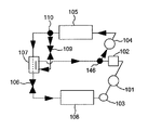
図1は、本発明の一実施例のスプリットサイクルを備えた冷凍装置を示すブロック図である。このスプリットサイクルは、二酸化炭素を冷媒として用い、高圧側の冷媒圧力(高圧圧力)がその臨界圧力以上(超臨界)となる二段圧縮一段膨張中間冷却サイクルである。当該スプリットサイクルは、圧縮手段を構成する低段側の圧縮要素101、インタークーラ102、2つの液体の流れを合流させる合流装置としての合流器146、同じく圧縮手段を構成する高段側の圧縮要素104、放熱器105、分流器110、補助絞り手段としての補助膨張弁109、中間熱交換器107、主絞り手段としての主膨張弁106、蒸発器108、アキュムレータ103とから冷凍サイクルが構成される。
(A) Split Cycle Apparatus FIG. 1 is a block diagram showing a refrigeration apparatus having a split cycle according to an embodiment of the present invention. This split cycle is a two-stage compression single-stage expansion intercooling cycle in which carbon dioxide is used as a refrigerant and the high-pressure side refrigerant pressure (high pressure) is equal to or higher than the critical pressure (supercritical). The split cycle includes a low-
上記放熱器105は、空気、又は、水、又は、その他の第2の熱媒体に高段側の圧縮要素104から出た高温高圧の冷媒を放熱させることによって当該高段側の圧縮要素104から出た冷媒を冷却するための熱交換器である。本実施例の放熱器105は、空気に放熱するガスクーラ熱交換器を用いるものとする。また、分流器110は、放熱器105から出た冷媒を二つの流れに分岐させる分流装置である。即ち、本実施例の分流器110は、放熱器105から出た冷媒を第1の冷媒流と第2の冷媒流とに分流し、第1の冷媒流を補助回路に流し、第2の冷媒流を主回路に流すように構成されている。
The
尚、図1における主回路とは、圧縮要素101、インタークーラ102、合流器6、圧縮要素104、放熱器105、分流器110、中間熱交換器107の第2の流路、主膨張弁106、蒸発器108、及び、アキュムレータ103からなる環状の冷媒回路であり、補助回路とは、分流器110から補助膨張弁109、中間熱交換器107の第1の流路を順次経て合流器146に至る回路を差す。
The main circuit in FIG. 1 is the
前記補助膨張弁109は、上記分流器110で分流され、補助回路を流れる第1の冷媒流を減圧するための補助絞り手段である。前記中間熱交換器107は、補助膨張弁109で減圧された補助回路の第1の冷媒流と分流器110で分流された第2の冷媒流との熱交換を行う熱交換器である。当該中間熱交換器107には第2の冷媒流が流れる第2の流路と上記第1の冷媒流が流れる第1の流路とが熱交換可能な関係で設けられており、該中間熱交換器107の第2の流路を通過することにより、第2の冷媒流は第1の流路を流れる第1の冷媒流により冷却されるので、蒸発器108における比エンタルピを小さくすることができる。
The
前記主膨張弁106は、上記中間熱交換器107で熱交換して冷却された第2の冷媒流を減圧するための主絞り手段である。そして、蒸発器108は、該主膨張弁106で減圧された第2の冷媒流の冷媒を水、又は、空気、又は、その他の第3の熱媒体とを直接又は間接的に熱交換させて蒸発させるためのものである。
The
以上の如く分流器110で分流された一方の冷媒流(第1の冷媒流)は、補助回路に入り、補助膨張弁109で減圧された後、中間熱交換器107の第1の流路を通過し、当該第1の通路を通過する過程で、第2の流路を通過する分流器110で分流された後の他方の冷媒流である第2の冷媒流と熱交換する。そして、補助回路を流れる該第1の冷媒流は、中間熱交換器107で熱交換した後、合流器146にて、低段側の圧縮要素101で圧縮されてインタークーラ102で冷却された後の第2の冷媒流と合流することになる。
As described above, one refrigerant flow (first refrigerant flow) divided by the
合流器146にて合流した後の冷媒は、圧縮手段の中間圧部(後述する実施例のロータリコンプレッサ10では密閉容器12内)である高段側の圧縮要素104の吸込ポートから吸い込まれるように構成されている。
The refrigerant after being merged by the
一方、図1で示される装置は以下の特徴を有するものとする。
(A−1)圧縮手段
前記圧縮手段を構成する各圧縮要素101、104は、それぞれモータを備えた2つの圧縮機から構成しても良いし、後述するように単一のモータで一体に結合された構成(1つのモータを持つ1つの圧縮機の中に2つの圧縮要素を備えた構成)としても良い。或いは、中間吸込ポートを設けた1つの圧縮要素を備える(この場合、インタークーラ102は無い)構成としても構わない。1つの圧縮要素の場合、圧縮機は吸込ポートと吐出ポートの間に中間吸込ポートを持ち、中間熱交換器107から流れ出た冷媒は、当該中間吸込ポートより圧縮要素に吸入される。尚、本実施例では、1つのインタークーラ102と2つの圧縮要素101、104から成るものとする。
On the other hand, the apparatus shown in FIG. 1 has the following characteristics.
(A-1) Compression means Each
(A−2)インタークーラ
インタークーラ102は、空気、水、その他の熱媒体と、低段側の圧縮要素101で圧縮されて高温となった冷媒(第2の冷媒流)との熱交換を行い、冷却するための熱交換器である。このインタークーラ102は本発明の必須の構成要素では無いので、設けても、設けなくてもよいが、設けた方が好ましい。本実施例では、インタークーラ102を設けるものとする。
(A-2) Intercooler The
(A−3)中間熱交換器の形式
中間熱交換器107において第2の流路を流れる第2の冷媒流と第1の流路を流れる第1の冷媒の流れ形式は対向流とすることが望ましいが、それに限定されるものでは無く、並行流、或いは、直交流、それらの組み合わせ、若しくは、その他の形式であってもよい。また、冷媒の流れに直交する任意断面における冷媒の温度が一様な混合流であっても、一様でない非混合流であってもよい。
(A-3) Type of intermediate heat exchanger In the
膨張弁106、109の制御については後述するが、当該各膨張弁106、109は2つの別々の弁から構成されるものとしても良く、或いは、1つの弁装置の中に一体に構成することも可能である。本発明の制御の概念は、冷凍装置への適用に止まらず、例えば、温水器、空気調和機、ヒートポンプやその他の冷却機器への応用など、蒸発器の温度レベルの全ての範囲のものに応用可能である。
Although the control of the
ここで、本実施例の冷凍装置は、冷媒として自然冷媒である二酸化炭素を使用するものとする。当該二酸化炭素冷媒は臨界圧力が低く、冷媒サイクルの高圧側が超臨界状態となることが知られている。係る超臨界冷媒サイクルにおいて、従来の単段の冷凍装置を使用すると、放熱器105側の熱源温度(例えば外気温度)が高いなどの原因により、放熱器105の出口の冷媒温度が高くなる条件下では、蒸発器108の入口冷媒の比エンタルピが大きくなり、冷凍効果が著しく低下する問題が生じていた。それにより、冷凍能力が低下するため、当該冷凍能力を確保するために高圧圧力を上昇させる必要があり、圧縮動力が増大して、成績係数(COP)も悪化する不都合が生じていた。
Here, the refrigeration apparatus of the present embodiment uses carbon dioxide, which is a natural refrigerant, as a refrigerant. It is known that the carbon dioxide refrigerant has a low critical pressure and the high pressure side of the refrigerant cycle is in a supercritical state. In such a supercritical refrigerant cycle, when a conventional single-stage refrigeration system is used, the refrigerant temperature at the outlet of the
そこで、放熱器105で冷却された後の冷媒を分流し、減圧膨張させた一方の補助回路を流れる第1の冷媒流により、分流された他方の主回路を流れる第2の冷媒流を冷却する、所謂、スプリットサイクル装置を用いることで、蒸発器108の入口の比エンタルピを小さくし、冷凍効果を大きくすることが可能となった。また、この場合、分流された補助回路の第1の冷媒流を圧縮手段の中間圧部、即ち、実施例では高段側の圧縮要素104に吸い込ませることで、低段側の圧縮要素101で圧縮する冷媒の量を減少させることができ、その結果圧縮動力が低下し、成績係数が向上する。
Therefore, the second refrigerant flow that flows through the other divided main circuit is cooled by the first refrigerant flow that flows through one auxiliary circuit that has been decompressed and expanded after the refrigerant that has been cooled by the
このように、スプリットサイクルによれば冷凍装置の性能改善を実現できるものである。しかしながら、実際の(従来の)冷凍装置では、第2の冷媒流を前もって冷却するという第1の冷媒流による冷却効果は、両冷媒が熱交換する熱交換器(実施例の中間熱交換器107に相等)に流れる冷媒量に依存するため、当該熱交換器に流れる第2の冷媒流と第1の冷媒流の流量を適切に制御する必要がある。そこで、本発明では係る性能を向上させるための適切な制御方法とそれに係る装置を提供する。
Thus, according to the split cycle, the performance improvement of the refrigeration apparatus can be realized. However, in the actual (conventional) refrigeration apparatus, the cooling effect by the first refrigerant flow that cools the second refrigerant flow in advance is that the heat exchanger (the
即ち、本発明は係る性能を向上させるための適切な制御方法とそれに係る装置を提供するものである。以下に本発明の冷凍装置の制御方法とその考え方について説明する。 That is, the present invention provides an appropriate control method for improving the performance and a device related thereto. The control method and concept of the refrigeration apparatus of the present invention will be described below.
(B)圧縮要素の容積比
低段側の圧縮要素101の排除容積に対する高段側の圧縮要素104の排除容積の比率(即ち、圧縮要素104の排除容積/圧縮要素101の排除容積。以下、容積比という)は、各々の圧縮要素101、104の吸込ポートを通過する冷媒の流量と密度に依存し、これは主回路の冷媒流量と補助回路の冷媒流量を決定する上で重要な要件である。本実施例では、容積比を0.3以上1.0以下の範囲内とする。更に好ましくは、容積比は0.5以上0.8以下の範囲内であり、本実施例の冷凍装置を用いた場合の最適な容積比は0.76である。当該最適容積比は、冷凍、冷蔵、冷房、その他の応用製品を想定したシミュレーションに基づき決定した。
(B) Compression element volume ratio Ratio of the displacement volume of the
図2に両圧縮要素101、104の容積比を上記最適容積比である0.76として、両圧縮要素101、104を同じ速度で運転し、冷房運転条件を想定したスプリットサイクルの最適運転のシュミレーション結果を示す。図2は上記容積比で冷房運転条件を想定したスプリットサイクルの最適運転条件において外気温度の変化に伴う各圧力の変化をプロットした図である。図2において、横軸は外気温度であり、当該冷房運転を想定した場合には当該外気温度は放熱器105にて冷媒と熱交換する熱媒体の温度に相当する。また、黒丸のプロットは膨張弁109で減圧された後の中間圧力の第1の冷媒流の圧力、黒三角のプロットは圧縮要素104で圧縮され、放熱器105に吸い込まれる高圧冷媒の圧力、白丸のプロットはアキュムレータ103内部の冷媒量をそれぞれ示している。
In FIG. 2, the compression ratio of both
尚、上記外気温度は当該シュミレーションのように冷房運転を想定した場合、放熱器105にて冷媒と熱交換する熱媒体の温度に相当し、暖房運転を想定した場合には被空調空間である室内温度、給湯器を想定した場合には給水温度に相当するものとする。
Note that the outside air temperature corresponds to the temperature of the heat medium that exchanges heat with the refrigerant in the
また、図2の左側の縦軸は、上記各冷媒の圧力を示し、右側の縦軸は冷媒量を示している。 Further, the left vertical axis in FIG. 2 indicates the pressure of each refrigerant, and the right vertical axis indicates the refrigerant amount.
図2に示すように、高圧冷媒の圧力は外気温度の上昇に伴い急激に上昇し、中間圧力の冷媒は外気温度が35℃と40℃の場合では、圧力に殆ど変化が無く、45℃で僅かに上昇するのみであった。 As shown in FIG. 2, the pressure of the high-pressure refrigerant rapidly increases as the outside air temperature rises, and the medium-pressure refrigerant has almost no change in pressure when the outside air temperature is 35 ° C. and 40 ° C. Only a slight increase.
(C)中間圧
最適な性能を実現するためには、補助膨張弁109を調整して中間圧を制御し、前述した如く補助膨張弁109で減圧された後の中間圧力の第1の冷媒流を最適な流量とする必要がある。即ち、補助膨張弁109を調節して、当該補助膨張弁109で減圧された後の補助回路を流れる冷媒(第1の冷媒流)を最適な中間圧とすることで、補助回路を流れる第1の冷媒流の冷媒流量を最適な値とすることができ、これにより、中間熱交換器107において、第2の冷媒流を効果的に冷却して、蒸発器108の入口の比エンタルピを小さくし、冷凍効果を大きくすることが可能となる。
(C) Intermediate pressure In order to achieve optimum performance, the intermediate pressure is controlled by adjusting the
ここで、目標とする中間圧(最適中間圧)を決定するための方法について以下に詳述する。 Here, a method for determining a target intermediate pressure (optimum intermediate pressure) will be described in detail below.
(C−1)圧縮手段の吸入側冷媒圧力と吐出側冷媒圧力から最適中間圧を決定する方法
先ず、圧縮手段の吸入圧力である低段側の圧縮要素101の吸入冷媒圧力と圧縮手段の吐出圧力である高段側の圧縮要素104の吐出冷媒圧力から圧縮手段の中間圧部の圧力を決定する方法について説明する。この場合、圧縮手段の吸入圧力と吐出圧力に基づいて前記補助膨張弁109を制御することにより、前記圧縮手段の中間圧部の圧力を決定する。
(C-1) Method for Determining Optimal Intermediate Pressure from Suction-side Refrigerant Pressure and Discharge-side Refrigerant Pressure of Compression Unit First, the suction refrigerant pressure of the low-
この場合、中間圧部の圧力が下記数式(1)に基づき算出された最適中間圧力となるように補助膨張弁109を制御する。
Pint,opt=Kint,opt*GMP=1.26*(Psuc*Pdis)0.5 ・・・(1)
上記数式(1)において、Pint,optは最適中間圧力、Kint,optは最適中間圧係数、GMPは高圧側圧力と低圧側圧力の相乗平均、Psucは圧縮要素101の吸入圧力(低圧側圧力)、Pdisは圧縮要素104の吐出圧力(高圧側圧力)をそれぞれ示している。
In this case, the
Pint, opt = Kint, opt * GMP = 1.26 * (Psuc * Pdis) 0.5 ... (1)
In the above formula (1), Pint, opt is the optimum intermediate pressure, Kint, opt is the optimum intermediate pressure coefficient, GMP is the geometric mean of the high pressure side pressure and the low pressure side pressure, and Psuc is the suction pressure (low pressure side pressure) of the
上記最適中間圧係数Kint,optは、本実施例の冷凍装置では1.26とすることが好ましいが、運転条件や装置の構造(例えば、圧縮要素101、104の容積比等)により、1.1以上1.6以下の範囲内で適宜決定するものとしても構わない。数式(1)より、高圧側圧力と低圧側圧力に基づき、目標とする最適中間圧力を算出し、当該最適中間圧力となるように補助膨張弁109を制御することで、補助回路を流れる第1の冷媒流の冷媒流量を最適な値とすることができる。これにより、中間熱交換器107において、第2の冷媒流を効果的に冷却して、蒸発器108の入口の比エンタルピを小さくし、冷凍効果を大きくすることが可能となる。
The optimum intermediate pressure coefficient Kint, opt is preferably 1.26 in the refrigeration apparatus of the present embodiment. However, depending on the operating conditions and the structure of the apparatus (for example, the volume ratio of the
一般に、圧縮手段における体積効率、断熱効率及び機械効率(以下これらをまとめて「圧縮効率」と記す)は、吸入側冷媒圧力に対する吐出側冷媒圧力の比率、所謂圧力比に依存する。即ち、圧力比が大きくなると、圧縮効率は低下する。そして、本実施例の圧縮手段のように、低段側の圧縮要素101と高段側の圧縮要素104を備えたものにおいて、低段側の圧縮要素と高段側の圧縮要素の圧力比が大きく相違し、いづれかの圧力比が著しく大きい場合には、当該圧力比が大きい側の圧縮要素での圧縮効率が著しく低下するため、冷凍サイクルの効率が低下することになる。そのため、低段側の圧縮要素と高段側の圧縮要素を備えた圧縮手段では、低段側の圧縮要素と高段側の圧縮要素の圧力比が等しくなる条件となるように中間圧力を決定することが望ましいとされている。
In general, volume efficiency, heat insulation efficiency, and mechanical efficiency (hereinafter collectively referred to as “compression efficiency”) in the compression means depend on a ratio of the discharge side refrigerant pressure to the suction side refrigerant pressure, so-called pressure ratio. That is, as the pressure ratio increases, the compression efficiency decreases. And, as in the compression means of this embodiment, in the case where the low-
前記の一般的に最適であるといわれている中間圧力は、低段側の圧縮要素の圧力比と高段側の圧縮要素の圧力比が等しいという関係より、吸入側冷媒圧力と吐出側冷媒圧力の相乗平均として表される。即ち、数式(1)において、最適中間圧係数Kint.optは1であるということになる。そして、このようにして求めた最適中間圧力となるように、圧縮手段の排除容積比率を設定する。即ち、低段側の圧縮要素及び高段側の圧縮要素、各々の吸入冷媒の比体積、体積効率、冷媒質量流量等から、圧縮手段の排除容積を求める。 The intermediate pressure, which is generally said to be optimal, is the suction side refrigerant pressure and the discharge side refrigerant pressure because the pressure ratio of the low-stage compression element is equal to the pressure ratio of the high-stage compression element. Expressed as the geometric mean of That is, in Equation (1), the optimum intermediate pressure coefficient Kint.opt is 1. Then, the excluded volume ratio of the compression means is set so that the optimum intermediate pressure obtained in this way is obtained. That is, the excluded volume of the compression means is obtained from the compression element on the low stage side and the compression element on the high stage side, the specific volume of each sucked refrigerant, volume efficiency, refrigerant mass flow rate, and the like.
このように、一般的に最適中間圧係数Kint.optは1であることが好ましいと考えられているが、本実施例の冷凍サイクルにおいては、必ずしもこの条件が最適な効率ではなく、前述のように、Kint.optは1.26とすることが好ましいということが、詳細な検討により判明した。本発明のスプリットサイクルでは、第1の冷媒流によって第2の冷媒流を冷却し、蒸発器に流入する冷媒の比エンタルピを小さくすることにより、冷凍サイクルの成績係数を向上させるものであるから、中間熱交換器107における熱交換が、サイクルの性能に及ぼす影響が大きいからである。
As described above, it is generally considered that the optimum intermediate pressure coefficient Kint.opt is preferably 1. However, in the refrigeration cycle of the present embodiment, this condition is not necessarily the optimum efficiency. Further, it was found by detailed examination that Kint.opt is preferably 1.26. In the split cycle of the present invention, the coefficient of performance of the refrigeration cycle is improved by cooling the second refrigerant flow with the first refrigerant flow and reducing the specific enthalpy of the refrigerant flowing into the evaporator. This is because heat exchange in the
そして、中間熱交換器107での熱交換性能は、熱交換を行なう冷媒の温度及び流量によって変化し、特に第1の冷媒流の温度及び流量による影響が大きい。そしてまた、第1の冷媒流の温度及び流量は補助膨張弁(補助絞り手段)109で減圧された後の圧力、即ち、中間圧力に密接な関連がある。尚、補助膨張弁109で減圧された後の補助回路は圧縮手段の中間圧部に繋がっているので、補助膨張弁108で減圧された後の中間圧力が結果的には圧縮手段の中間圧部の圧力として把握できる。
The heat exchange performance in the
具体的には、中間圧力が最適な値よりも高いと、補助膨張弁109による減圧幅が小さく、減圧された後の第1の冷媒流の冷媒温度も高いということになる。そのため、中間熱交換器107において、第1の冷媒流によって冷却された後の第2の冷媒流の温度は、第1の冷媒流の中間熱交換器107入口温度よりも低くなることはないから、このように中間圧力が高く、補助膨張弁109で減圧された後の第1の冷媒流の温度が高い場合には、中間熱交換器107出口での第2の冷媒流の温度も高くなる。従って、蒸発器108入口での冷媒の比エンタルピを小さくして、冷凍効果を大きくするというスプリットサイクルの性能向上効果も小さくなる。
Specifically, when the intermediate pressure is higher than the optimum value, the pressure reduction range by the
他方、中間圧力が最適値より低くなると、補助回路を流れる第1の冷媒流の流量は徐々に低下する。そして更に中間圧力を低くすると、補助回路を流れる冷媒が全くなくなり、通常の一段膨張冷凍サイクルと同じになる。補助膨張弁109を通過した冷媒の圧力が、前記のように補助回路を流れる冷媒が全くない場合の中間圧力より高くなる条件でなければ、冷媒は補助回路から圧縮手段の中間圧力部へと流れることができないからである。このように補助回路を流れる第1の冷媒流の流量が減少すると、低段側の圧縮要素101で圧縮する冷媒の量を減らして圧縮動力を削減することにより成績係数を向上させるというスプリットサイクルの効果が小さくなる。また、中間熱交換器107で熱交換される熱量は、各々の冷媒について、中間熱交換器107の入口と出口のエンタルピ差と流量との積で表されるので、熱収支を考えると、第1の冷媒の流量が減ることは、中間熱交換器107出口における第2の冷媒の比エンタルピが高くなることを意味する。従って、第1の冷媒流により第2の冷媒流を冷却することによって性能を向上させるというスプリットサイクルの効果が小さくなることになる。そして更に中間圧力が低くなり、補助回路を流れる冷媒が全くなくなると、もはやスプリットサイクルの効果は全く得られなくなる。
On the other hand, when the intermediate pressure becomes lower than the optimum value, the flow rate of the first refrigerant flow flowing through the auxiliary circuit gradually decreases. When the intermediate pressure is further lowered, there is no refrigerant flowing through the auxiliary circuit, which is the same as a normal one-stage expansion refrigeration cycle. Unless the pressure of the refrigerant that has passed through the
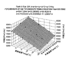
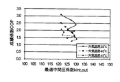
本発明は、上記のような、中間圧力とスプリットサイクルの性能改善効果との相関に着目し、最適な運転条件を実現し、冷凍サイクルの性能の向上を図ろうとするものである。図8は、蒸発温度と外気温度を運転条件パラメータとして変化させ、各々の運転条件において成績係数が最大となる最適中間圧係数Kint.optをプロットしたものである。前述のように、圧縮手段の中間圧部の圧力と、主回路及び補助回路の冷媒流量比率、並びに中間圧力は、圧縮手段の排除容積比に依存するため、最適中間圧力及び最適中間圧力係数も、排除容積比の影響を受ける。図8は、排除容積比を0.76として検討した結果である。排除容積比0.76としたのは、全運転条件について総合的に判断し好適であったからである。 The present invention pays attention to the correlation between the intermediate pressure and the performance improvement effect of the split cycle as described above, and aims to improve the performance of the refrigeration cycle by realizing optimum operating conditions. FIG. 8 plots the optimum intermediate pressure coefficient Kint.opt that maximizes the coefficient of performance under each operating condition by changing the evaporation temperature and the outside air temperature as the operating condition parameters. As described above, since the pressure of the intermediate pressure portion of the compression means, the refrigerant flow ratio of the main circuit and the auxiliary circuit, and the intermediate pressure depend on the excluded volume ratio of the compression means, the optimum intermediate pressure and the optimum intermediate pressure coefficient are also , Affected by the excluded volume ratio. FIG. 8 shows the results of examination with an excluded volume ratio of 0.76. The reason why the excluded volume ratio is set to 0.76 is that it is preferable to comprehensively judge all operating conditions.
図8から、蒸発温度と外気温度を変化させた場合において、最適中間圧係数Kint.optは1.2から1.3の間に分布していることが分かる。従って、数式(1)において、最適中間圧係数Kint.optを1.2以上1.3以下とすることが望ましい。そして、最適中間圧係数Kint.optを1.2以上1.3以下の範囲内にある所定の値として、吸入冷媒圧力及び吐出冷媒圧力から、数式(1)に基づいて最適中間圧力を求め、圧縮手段の中間圧部の圧力(即ち、前記中間圧力)を前記最適中間圧力になるように制御することにより、外気温度及び蒸発温度が変化する条件において、高効率な運転を行なうことができる。 FIG. 8 shows that the optimum intermediate pressure coefficient Kint.opt is distributed between 1.2 and 1.3 when the evaporation temperature and the outside air temperature are changed. Therefore, in the formula (1), it is desirable that the optimum intermediate pressure coefficient Kint.opt is 1.2 or more and 1.3 or less. Then, the optimum intermediate pressure coefficient Kint.opt is set to a predetermined value within the range of 1.2 to 1.3, and the optimum intermediate pressure is obtained from the intake refrigerant pressure and the discharge refrigerant pressure based on the formula (1). By controlling the pressure of the intermediate pressure portion of the compression means (that is, the intermediate pressure) to be the optimum intermediate pressure, a highly efficient operation can be performed under conditions where the outside air temperature and the evaporation temperature change.
最適中間圧係数Kint.optが1.3より大きい場合は、中間圧力が高くなりすぎ、冷凍サイクル高圧サイドの冷媒圧力と中間圧力との圧力差が小さくなる。即ち、補助膨張弁109での減圧幅が小さくなるので、補助膨張弁109における冷媒の温度降下が小さくなり、中間熱交換器107入口での第1の冷媒流の温度が高くなり、その結果、中間熱交換器107で熱交換後の第2の冷媒流の温度が高くなり、蒸発器108入口での冷媒の比エンタルピを小さくするというスプリットサイクルの性能改善効果が小さくなってしまう。従って、成績係数が低くなってしまう。他方、最適中間圧係数Kint.optが1.2より小さい場合には、中間圧力が低くなりすぎ、補助回路を流れる第1の冷媒流の流量が小さくなり、その結果、第2の冷媒流の流量が多くなり、低段側の圧縮要素101で圧縮する冷媒の流量を減らし圧縮動力を削減するというスプリットサイクルの効果が小さくなる。また同時に、第1の冷媒流の流量が小さくなることにより、中間熱交換器107での交換熱量が小さくなり、中間熱交換器107で熱交換後の第2の冷媒流の温度が高くなり、蒸発器108入口での冷媒の比エンタルピを小さくするというスプリットサイクルの性能改善効果が小さくなってしまう。従って、成績係数が低くなってしまう。
When the optimum intermediate pressure coefficient Kint.opt is larger than 1.3, the intermediate pressure becomes too high, and the pressure difference between the refrigerant pressure on the high-pressure side of the refrigeration cycle and the intermediate pressure becomes small. That is, since the pressure reduction width at the
また、冷凍装置の用途から使用条件がより具体的に想定できる場合においては、その想定される使用条件に応じて最適な性能が得られるように、排除容積比及び最適中間圧係数Kint.optを決めることができる。例えば、排除容積比をより小さくした場合には、最適中間圧係数Kint.optはより大きな値とすることができ、これとは反対に、排除容積比をより大きくした場合には、最適中間圧係数Kint.optはより小さな値とすることができる。 In addition, when the usage conditions can be estimated more specifically from the application of the refrigeration system, the exclusion volume ratio and the optimal intermediate pressure coefficient Kint.opt should be set so that optimal performance can be obtained according to the assumed usage conditions. I can decide. For example, the optimum intermediate pressure coefficient Kint.opt can be set to a larger value when the excluded volume ratio is smaller, and conversely, when the excluded volume ratio is larger, the optimum intermediate pressure coefficient The coefficient Kint.opt can be a smaller value.
前述のように、想定される運転条件に応じて、排除容積比を0.3以上1以下の範囲内にある所定の値、更に好ましくは、0.5以上0.8以下の範囲内にある所定の値とし、最適中間圧係数Kint.optは1.1以上1.6以下の範囲内にある所定の値とすることができる。 As described above, the excluded volume ratio is a predetermined value in the range of 0.3 or more and 1 or less, more preferably in the range of 0.5 or more and 0.8 or less, depending on the assumed operating conditions. The optimum intermediate pressure coefficient Kint.opt can be a predetermined value in the range of 1.1 to 1.6.
このように排除容積比を変更した場合であっても、最適中間圧係数Kint.optが1.6を超えると、中間圧力と高圧側圧力との圧力差が殆どなくなり、第1の冷媒流による第2の冷媒流を冷却する効果は得られず、第1の冷媒流の流量が極端に多く、第2の冷媒流が極端に少なくなり、冷凍サイクルの効率が著しく低下する。 Even when the excluded volume ratio is changed in this way, when the optimum intermediate pressure coefficient Kint.opt exceeds 1.6, there is almost no pressure difference between the intermediate pressure and the high-pressure side pressure, and the first refrigerant flow The effect of cooling the second refrigerant flow is not obtained, the flow rate of the first refrigerant flow is extremely large, the second refrigerant flow is extremely small, and the efficiency of the refrigeration cycle is significantly reduced.
他方、最適中間圧係数Kint.optが1.1より小さくなると、中間圧力が低くなり、第1の冷媒流の流量が極端に少なくなり、放熱器を通過した後の冷媒を分流して第2の冷媒流の流量を削減することにより低段側の圧縮要素101での冷媒流量を減らし圧縮動力を削減するという効果が著しく低下すると共に、第1の冷媒流による第2の冷媒流を冷却する効果が著しく低下し、スプリットサイクルによる成績係数の向上が殆ど得られないことになる。
On the other hand, when the optimum intermediate pressure coefficient Kint.opt is smaller than 1.1, the intermediate pressure is lowered, the flow rate of the first refrigerant flow is extremely reduced, and the second refrigerant is divided by passing the refrigerant after passing through the radiator. By reducing the flow rate of the refrigerant flow, the effect of reducing the flow rate of refrigerant in the low-
このように、高圧側圧力と低圧側圧力に基づき、数式(1)から目標とする最適中間圧力を算出し、当該最適中間圧力となるように補助膨張弁109を制御することで、最適な性能が実現可能となる。これにより、二酸化炭素冷媒を用いた冷凍装置の冷凍能力を改善して、性能を向上させることができるようになる。
As described above, based on the high-pressure side pressure and the low-pressure side pressure, the target optimum intermediate pressure is calculated from the formula (1), and the
(C−2)蒸発温度と外気温度から最適中間圧を決定する方法
次に、蒸発温度から圧縮手段の中間圧部の圧力を決定する方法について説明する。この場合、蒸発器108における冷媒の蒸発温度及び外気温度に基づき、補助膨張弁109を制御することにより、圧縮手段の中間圧部の圧力を決定する。
(C-2) Method for Determining Optimal Intermediate Pressure from Evaporation Temperature and Outside Air Temperature Next, a method for determining the pressure of the intermediate pressure portion of the compression means from the evaporation temperature will be described. In this case, the pressure of the intermediate pressure portion of the compression means is determined by controlling the
ここで、図1の冷凍装置を冷凍、冷蔵、空調(冷房及び暖房)、更に、その他の応用製品として使用することを想定して蒸発温度と外気温度の変化に基づき、それぞれの最適中間圧力を求めた結果を図3に示す。図3は蒸発温度、外気温度及び最適中間圧の関係を示す曲線図である。図3に示す結果から下記相関関係を示す数式(2)を導くことができる。
z=a+bx+cy+dx2+ey2+fxy ・・・(2)
Here, assuming that the refrigeration apparatus of FIG. 1 is used for freezing, refrigeration, air conditioning (cooling and heating), and other application products, the respective optimum intermediate pressures are determined based on changes in evaporation temperature and outside air temperature. The obtained results are shown in FIG. FIG. 3 is a curve diagram showing the relationship between the evaporation temperature, the outside air temperature, and the optimum intermediate pressure. From the results shown in FIG. 3, the following formula (2) showing the correlation can be derived.
z = a + bx + cy + dx 2 + ey 2 + fxy (2)
数式(2)において、zは目標とする最適中間圧、xは外気温度、yは蒸発温度である。また、a、b、c、d、e、fは係数であり、図3に示す結果から、本実施例の冷凍装置において、係数aは5041.2944、係数bは33.280952、係数cは35.452619、係数dは0.70333333、係数eは0.40309524、係数fは1.2085714とすることが最も好ましい。 In Equation (2), z is a target optimum intermediate pressure, x is an outside air temperature, and y is an evaporation temperature. Further, a, b, c, d, e, and f are coefficients. From the results shown in FIG. 3, in the refrigeration apparatus of the present example, the coefficient a is 5041.2944, the coefficient b is 33.280952, and the coefficient c is 35.452619, coefficient d is 0.70333333, coefficient e is 0.40309524, and coefficient f is most preferably 1.20857714.
このように、想定される運転条件に応じて、上記数式(2)により最適中間圧を求めて、当該最適中間圧となるように補助膨張弁109を制御する。実際には、数式(2)により求められた値の±50%の範囲内、好ましくは、±20%の範囲内となるように補助膨張弁109を制御することで、補助回路を流れる第1の冷媒流の冷媒流量を最適な値とすることができる。これにより、中間熱交換器107において、第2の冷媒流を効果的に冷却して、蒸発器108の入口の比エンタルピを小さくし、冷凍効果を大きくすることが可能となる。
As described above, the optimum intermediate pressure is obtained by the above formula (2) according to the assumed operating condition, and the
このように、蒸発温度と外気温度に基づいて、数式(2)から目標とする最適中間圧を算出し、当該最適中間圧の±20%の範囲内の圧力となるように補助膨張弁109を制御することで、最適な性能が実現可能となる。これにより、二酸化炭素冷媒を用いた冷凍装置の冷凍能力を改善して、性能を向上させることができるようになる。また、上記数式(2)は全運転条件において適用できるものである。尚、本実施例では上記各係数a、b、c、d、e、fを上述の数値とすることが最も好ましいが、各係数a、b、c、d、e、fの数値は実際の冷凍装置の構造に依存するものであり、容積比のような変数が作用して決定された値であることに留意する必要がある。
Thus, based on the evaporation temperature and the outside air temperature, the target optimum intermediate pressure is calculated from Equation (2), and the
(C−3)一定の中間圧に制御する方法
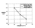
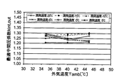
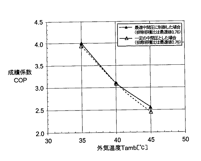
一方、前記図2に示す冷房運転のシュミレーションの結果から高圧側圧力と中間圧力は共に外気温度に依存するが、中間圧の外気温度依存性は高圧側圧力に比べて非常に低く、外気温度が変化しても最適な中間圧力の値は7.5MPaから8.0MPaの範囲内であり、大きく変化しないことがわかる。これは中間圧を予め設定した所定(一定)の値となるように制御した場合、その装置が最適な性能に近づいて制御される可能性があることを示している。ここで、中間圧部の圧力が最適中間圧となるように制御した場合と、予め設定した所定の圧力にとなるように制御した場合とで性能を比較すると、図4に示す結果が得られた。図4において、実線は最適中間圧となるように制御した場合の外気温度変化に伴う成績係数(COP)の変化、破線は中間圧を所定の値(例えば、7.75MPa)となるように制御した場合の外気温度変化に伴う成績係数の変化をそれぞれ示している。
(C-3) Method of controlling to a constant intermediate pressure On the other hand, both the high-pressure side pressure and the intermediate pressure depend on the outside air temperature from the results of the cooling operation simulation shown in FIG. 2, but the dependence of the intermediate pressure on the outside air temperature is It is very low compared with the high-pressure side pressure, and it can be seen that the optimum intermediate pressure value is in the range of 7.5 MPa to 8.0 MPa even if the outside air temperature changes, and does not change greatly. This indicates that when the intermediate pressure is controlled to be a predetermined (constant) value set in advance, the apparatus may be controlled to approach optimum performance. Here, when the performance is compared between the case where the pressure of the intermediate pressure portion is controlled to be the optimum intermediate pressure and the case where the pressure is controlled to be a predetermined pressure set in advance, the result shown in FIG. 4 is obtained. It was. In FIG. 4, the solid line indicates a change in coefficient of performance (COP) accompanying a change in the outside air temperature when control is performed so as to achieve the optimum intermediate pressure, and the broken line indicates that the intermediate pressure is set to a predetermined value (for example, 7.75 MPa). The change in the coefficient of performance accompanying the change in the outside air temperature is shown respectively.
図4に示すように、中間圧を予め設定した所定(一定)の値となるように制御した場合の性能と中間圧部の圧力が最適中間圧となるように制御した場合の性能とではほぼ同じ性能となることがわかる。従って、中間圧を所定の値となるように制御することで、略最適な性能が得られることが明らかである。 As shown in FIG. 4, the performance when the intermediate pressure is controlled to be a predetermined (constant) value set in advance and the performance when the pressure of the intermediate pressure portion is controlled to be the optimum intermediate pressure are almost the same. It turns out that it becomes the same performance. Therefore, it is apparent that substantially optimal performance can be obtained by controlling the intermediate pressure to be a predetermined value.
この場合、目標とする所定の中間圧は、装置の用途に応じて予め想定される運転条件を考慮し、前記数式(1)又は数式(2)から求めることができる。このとき、数式(1)又は数式(2)から求められる値の±50%の範囲内の圧力とし、好ましくは±20%の範囲内の圧力となるように補助膨張弁109を制御するものとする。
In this case, the target predetermined intermediate pressure can be obtained from the formula (1) or the formula (2) in consideration of the operation condition assumed in advance according to the use of the apparatus. At this time, the
このように、補助膨張弁109により、中間圧を予め設定した所定の値で一定となるように制御するという簡単な制御方法であっても、上記(C−1)及び(C−2)と同様に装置の性能の向上を図ることができる。
Thus, even with a simple control method in which the intermediate pressure is controlled to be constant at a predetermined value set in advance by the
(C−4)最適高圧側圧力
他方、最適な性能を実現するためには、上述の如く補助膨張弁109により中間圧を制御するだけでなく、主膨張弁106を高圧側圧力が最適となるように制御する必要がある。ここで、高圧側圧力の制御方法について詳述する。前記図2で示すように高圧側圧力も外気温度に依存することが明らかである。更に、高圧側圧力は蒸発器108における冷媒の蒸発温度にも依存する。以上より、下記の数式(3)に基づき、高圧側圧力を制御するものとする。この相関関係は98.9%の信頼性がある。
Pdis=a+bTamb+cTevap+dTamb 2+eTevap 2+fTambTevap ・・・(3)
(C-4) Optimal High Pressure Side Pressure On the other hand, in order to realize optimal performance, not only the intermediate pressure is controlled by the
P dis = a + bT amb + cT evap + dT amb 2 + eT evap 2 + fT amb T evap (3)
上記数式(3)において、Pdisは高段側の圧縮要素104の吐出側冷媒圧力(高圧側圧力)、Tambは外気温度、Tevapは蒸発温度をそれぞれ示している。また、a、b、c、d、e及びfは係数であり、aを−1854.91508、bを334.4838095、cを−98.3269048、dを−0.60666667、eを0.932619048、fを3.522285714とする。
In the above formula (3), P dis represents the discharge side refrigerant pressure (high pressure side pressure) of the high- stage
このように、蒸発温度と外気温度を検出し、当該数式(3)により目標とする高圧側圧力を求め、主膨張弁106を調節して高圧側圧力を制御することによって、冷凍装置の最適な運転条件を実現することが可能となり、冷凍装置の性能を向上させることができる。
In this way, by detecting the evaporation temperature and the outside air temperature, obtaining the target high-pressure side pressure according to the mathematical formula (3), and adjusting the
尚、本実施例では最適高圧側圧力を蒸発温度と外気温度に基づき求めるものとしたが、制御方法としては、外気温度を放熱器105の出口の冷媒温度に代用することが可能である。また、外気温度は、暖房運転を想定した場合には室温、給湯器を想定した場合には給水温度で代用することが可能である。一方、蒸発温度は蒸発圧力でも代用可能であり、冷房運転を想定した場合には室温や目標設定室温等でも代用可能である。
In this embodiment, the optimum high-pressure side pressure is obtained based on the evaporation temperature and the outside air temperature. However, as a control method, the outside air temperature can be substituted for the refrigerant temperature at the outlet of the
また、主膨張弁106の具体的形態については特に限定はなく、一般的冷凍装置に用いられる電子式膨張弁やその他の絞り手段を採用することが可能である。
Moreover, there is no limitation in particular about the specific form of the
補助回路の絞り手段としての補助膨張弁109は、一般的な電子式膨張弁やその他の絞り手段を使用することが可能であるが、一定の中間圧力に制御する方法では、中間圧力を検出する手段が必要無く、簡単な方法で制御することが可能な均圧型定圧膨張弁が好ましい。
As the
(C−5)温度による制御方法
従来の単段型のサイクルでは、絞り手段による減圧で一部の冷媒が蒸発していた。即ち、蒸発器に入る前に一部の冷媒が蒸発し、その蒸発により残りの冷媒が冷却されていた。従って、蒸発器入口では蒸発して最早蒸発による冷凍効果を発揮しない蒸気冷媒と、蒸発した冷媒によって冷却されエンタルピが低くなった液冷媒が混在することとなる。このように、絞り手段で蒸発した冷媒は蒸発器において蒸発しないため、冷凍に寄与できない。これにより、蒸発器における冷凍効果が著しく低減する問題が生じていた。更に、係る冷媒は既に低圧となっているため、これを圧縮して高圧に戻すための圧縮動力が必要であった。
(C-5) Temperature-based control method In the conventional single-stage cycle, a part of the refrigerant was evaporated by the pressure reduction by the throttle means. That is, a part of the refrigerant evaporates before entering the evaporator, and the remaining refrigerant is cooled by the evaporation. Therefore, a vapor refrigerant that evaporates at the evaporator inlet and no longer exhibits the refrigeration effect due to evaporation is mixed with a liquid refrigerant that is cooled by the evaporated refrigerant and has a low enthalpy. Thus, since the refrigerant evaporated by the throttle means does not evaporate in the evaporator, it cannot contribute to refrigeration. Thereby, the problem that the freezing effect in an evaporator reduces remarkably has arisen. Further, since the refrigerant is already at a low pressure, a compression power is required to compress the refrigerant and return it to a high pressure.
しかしながら、2段のスプリットサイクルでは、中間熱交換器107において、分流器110にて分流された一方の補助回路冷媒(第1の冷媒流)を補助膨張弁(補助絞り手段)109にて減圧し、この減圧された補助回路冷媒(第1の冷媒流)の熱により主回路冷媒(第2の冷媒流)を予め冷却することができる。
However, in the two-stage split cycle, in the
この場合、主膨張弁106における熱の受け渡しについては従来の単段型のサイクルと同様であるが、主回路冷媒を冷却した後の補助回路冷媒の圧力は低圧ではなく中間圧であるため、冷凍に寄与しない冷媒を高圧に戻す為の圧縮動力は従来の単段型のサイクルと比べて著しく小さくなる。
In this case, the heat transfer in the
これにより、中間熱交換器107において補助回路を流れる第1の冷媒流で主回路を流れる第2の冷媒流をより効率的に冷却することができ、性能の向上を図ることができるようになる。
As a result, the second refrigerant flow flowing through the main circuit can be more efficiently cooled by the first refrigerant flow flowing through the auxiliary circuit in the
上述の如く中間熱交換器107により主回路を流れる第2の冷媒流を冷却して、冷凍装置の性能を向上できることが明らかであるが、係る第2の冷媒流を冷却する補助流の効果は前述の如く中間熱交換器107の容量(中間熱交換器107にて熱交換される第1の冷媒流と第2の冷媒流の量)に依存する。そこで、次に中間熱交換器107の入口或いは出口における第1の冷媒流若しくは第2の冷媒流の温度を制御する方法について詳述する。
As described above, it is obvious that the performance of the refrigeration apparatus can be improved by cooling the second refrigerant flow flowing through the main circuit by the
(I)中間熱交換器107として対向流型熱交換器を使用する場合。
先ず、中間熱交換器107として、第1の冷媒流と第2の冷媒流とが対向して流れる対向流型熱交換器を使用する場合について説明する。この場合、以下の(a)〜(f)の5つの方法があり、何れか一つの方法を用いれば良い。
(I) When a counter-flow heat exchanger is used as the
First, the case where a counter flow type heat exchanger in which the first refrigerant flow and the second refrigerant flow are opposed to each other is used as the
(a)中間熱交換器107を出る第1の冷媒流の温度を中間熱交換器107に入る第2の冷媒流の温度に応じて制御する。具体的には、中間熱交換器107を出る第1の冷媒流の温度が、中間熱交換器107に入る第2の冷媒流の温度の所定範囲以内となるように制御する。この場合、所定温度とは、中間熱交換器107の流れの形式に拘わらず(即ち、中間熱交換器107が対向流型の熱交換器であっても、その他の形式の熱交換器であっても)、その容量と装置の他の要素との関係や装置の運転条件等に依存するものであり、本実施例では、中間熱交換器107を出る第1の冷媒流の温度が中間熱交換器107に入る第2の冷媒流の温度に対して、5Kの範囲内に制御することが好ましく、更には2K以内に制御することが望ましい。
(A) The temperature of the first refrigerant stream exiting the
(b)中間熱交換器107を出る第2の冷媒流の温度を中間熱交換器107に入る第1の冷媒流の温度に応じて制御する。具体的には、中間熱交換器107から出る第2の冷媒流の温度が、中間熱交換器107に入る第1の冷媒流の温度の所定範囲以内となるように制御する。この場合も、所定温度とは上述同様に中間熱交換器107の流れの形式に拘わらず、その容量と装置の他の要素との関係や装置の運転条件等に依存するものであり、本実施例では、中間熱交換器107を出る第2の冷媒流の温度を中間熱交換器107に入る第1の冷媒流の温度に対して、5Kの範囲内に制御することが好ましく、更には2K以内に制御することが望ましい。
(B) controlling the temperature of the second refrigerant stream exiting the
(c)中間熱交換器107から出る第1の冷媒流の温度は、放熱器105に入る第2の熱媒体(水、空気、或いはその他の熱媒体)の温度に応じて制御する。具体的には、中間熱交換器107から出る第1の冷媒流の温度が放熱器105に入る第2の熱媒体の温度の所定範囲以内となるように制御する。この場合も、所定温度とは上述同様に中間熱交換器107の流れの形式に拘わらず、その容量と装置の他の要素との関係や装置の運転条件等に依存するものであり、本実施例では、中間熱交換器107から出る第1の冷媒流の温度を放熱器105に入る第2の熱媒体の温度に対して、8Kの範囲以内に制御することが好ましく、更には4K以内に制御することが望ましい。
(C) The temperature of the first refrigerant flow exiting from the
(d)中間熱交換器107から出る第1の冷媒流と中間熱交換器107に入る第2の冷媒流との温度差は予め設定された所定範囲以内となるように制御する。この所定温度とは上述の如く中間熱交換器107の流れの形式に拘わらず、その容量と装置の他の要素との関係や装置の運転条件等に依存するものであり、本実施例では、中間熱交換器107から出る第1の冷媒流の温度を中間熱交換器107に入る第2の冷媒流の温度に対して、5Kの範囲以内に制御することが好ましく、更に好ましくは2K以内に制御することが良い。
(D) The temperature difference between the first refrigerant flow exiting the
(e)中間熱交換器107に入る第1の冷媒流と中間熱交換器107から出る第2の冷媒流の間の温度差は予め設定された所定範囲以内となるように制御する。この所定温度とは上述の如く中間熱交換器107の流れの形式に拘わらず、その容量と装置の他の要素との関係や装置の運転条件等に依存するものであり、本実施例では、係る温度差を5Kの範囲以内に制御することが好ましく、更に好ましくは2K以内に制御することが良い。
(E) The temperature difference between the first refrigerant flow entering the
(II)中間熱交換器107として平行流型熱交換器を使用する場合。
次に、中間熱交換器107として、第1の冷媒流と第2の冷媒流とが平行して流れる平行流型熱交換器を使用する場合について説明する。この場合も以下に述べる(a)〜(d)の4つの方法があり、何れか一つの方法を用いればよい。
(II) When a parallel flow heat exchanger is used as the
Next, a case where a parallel flow heat exchanger in which the first refrigerant flow and the second refrigerant flow flow in parallel is used as the
(a)中間熱交換器107を出る補助流(第1の冷媒流)の温度が中間熱交換器107に入る主流(第2の冷媒流)の温度の所定範囲以内となるように制御する。実際の所定温度の値は、中間熱交換器107の流れの型式(対向流型或いは平行流型)に拘わらず、その容量と装置の他の要素との関係や装置の運転条件等に依存するものであり、本実施例では、中間熱交換器107を出る第1の冷媒流の温度を中間熱交換器107に入る第2の冷媒流の温度の12Kの範囲内に制御することが好ましく、更に好ましくは6K以内に制御するものとする。
(A) Control is performed so that the temperature of the auxiliary flow (first refrigerant flow) exiting the
(b)中間熱交換器107を出る第2の冷媒流の温度が中間熱交換器107に入る第1の冷媒流の温度の所定範囲以内となるように制御する。実際の所定温度の値は、中間熱交換器107の流れの型式に拘わらず、その容量と装置の他の要素との関係や装置の運転条件等に依存するものであり、本実施例では、中間熱交換器107を出る第2の冷媒流の温度を中間熱交換器107に入る第1の冷媒流の温度の12Kの範囲内に制御することが好ましく、更に好ましくは6K以内に制御するものとする。
(B) Control so that the temperature of the second refrigerant stream exiting the
(c)中間熱交換器107から出る第1の冷媒流の温度が放熱器105に入る第2の熱媒体(水、空気、或いはその他の熱媒体)の温度の所定範囲以内となるように制御する。実際の所定温度の値は、中間熱交換器107の流れの型式に拘わらず、その容量と装置の他の要素との関係や装置の運転条件等に依存するものであり、本実施例では、中間熱交換器107を出る第1の冷媒流の温度を放熱器105に入る第2の熱媒体の温度の15Kの範囲内に制御することが好ましく、更に好ましくは8K以内に制御するものとする。
(C) Control so that the temperature of the first refrigerant flow exiting the
(d)中間熱交換器107から出る第1の冷媒流と中間熱交換器107から出る第2の冷媒流との温度差は予め設定された所定範囲内となるように制御する。実際の所定温度の値は、中間熱交換器107の流れの型式に拘わらず、その容量と装置の他の要素との関係や装置の運転条件等に依存するものであり、本実施例では温度差を5Kの範囲以内に制御することが好ましく、更に好ましくは温度差を2K以下に制御するものとする。絞り手段は限定しないが、本実施例のように温度による制御を行う場合には、温度式自動膨張弁が好ましい。
(D) The temperature difference between the first refrigerant flow exiting from the
(C−6)固定絞り手段による方法
(a)固定絞り手段の流路面積
上述した制御方法は主膨張弁と補助膨張弁の2つの制御手段を用いて最適又は略最適な運転を行い、冷凍装置の性能を向上させるものであるが、次に、補助回路の絞り手段として上記制御方法より更に簡易な方法である固定絞り手段を用いた方法について説明する。尚、本実施例では三洋電機株式会社により製造された排除容積比が0.576のコンプレッサを用いた。
(C-6) Method by means of fixed throttle means (a) Channel area of fixed throttle means The control method described above performs optimal or substantially optimal operation using two control means of the main expansion valve and the auxiliary expansion valve, and freezing In order to improve the performance of the apparatus, a method using fixed throttle means, which is a simpler method than the above control method, will now be described as throttle means for the auxiliary circuit. In this embodiment, a compressor having an excluded volume ratio of 0.576 manufactured by Sanyo Electric Co., Ltd. was used.
この場合、固定絞りのオリフィス流路面積は以下に示す数式(4)により算出した(ASHRAE Handbook, Fundamentals, 1997, p.2.11)。
尚、上記数式(4)においてCdは面取りオリフィスの流出係数、Aoはオリフィス流路面積(pi/4*Do^2)、kは比熱比(CP1/CV1)、Rはガス定数であり、本実施例では当該Cdを0.8、Rを8314.41/44(J/kg−K)、C1を((2*k)/(R*(k−1)))^0.5とする。 In the above equation (4), Cd is the outflow coefficient of the chamfered orifice, Ao is the orifice channel area (pi / 4 * Do ^ 2), k is the specific heat ratio (CP1 / CV1), and R is the gas constant. In this embodiment, Cd is 0.8, R is 8314.41 / 44 (J / kg-K), and C1 is ((2 * k) / (R * (k-1))) ^ 0.5. .
当該数式(4)を用いて、各種運転条件での主回路及び補助回路の絞り手段のオリフィス流路面積を算出した。この結果を表1に示す。表1に示すように主回路の絞り手段のオリフィス流路面積は外気温度や蒸発温度に依存して大きく変化し、その標準偏差は22.6%である。一方、補助回路の絞り手段のオリフィス流路面積は広範囲の運転条件においても大きな変化が無く、その標準偏差は7.9%である。これらの結果は図5の如くグラフ化すると更に明確となる。即ち、主回路の絞り手段のオリフィス流路面積は外気温度の上昇に伴って直線的に減少し、蒸発温度の上昇により増加するが、補助回路の絞り手段のオリフィス流路面積は外気温度や蒸発温度によらず略一定であることがわかる。
以上の結果から補助回路の絞り手段として、キャピラリチューブやその他の固定絞り手段を用いることが可能であることが明らかである。 From the above results, it is clear that a capillary tube or other fixed throttle means can be used as the throttle means of the auxiliary circuit.
(b)補助回路に固定絞り手段を用いた場合の成績係数(COP)の変化
上述の如く補助回路の絞り手段として、キャピラリチューブやその他固定絞り手段を用いることが可能であるが、次に、このような固定絞り手段を採用した場合と絞り手段の開度を適度に操作して最適な中間圧力となるように制御した場合とで冷凍装置の性能を比較した結果を表2に示す。表2に示すように、補助回路の絞り手段として固定絞り手段を採用した場合と絞り開度を調節して最適な性能となるように制御した場合とでは、性能に大きな変化は無く、殆ど同じであることがわかる。
従って、補助回路の絞り手段としてキャピラリチューブやその他の固定絞り手段を用いるという簡易な方法で略最適な運転状態が実現され、冷凍装置の性能を向上させることができる。 Therefore, a substantially optimal operation state is realized by a simple method of using a capillary tube or other fixed throttle means as the throttle means of the auxiliary circuit, and the performance of the refrigeration apparatus can be improved.
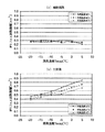
図6は図5の2次元図である。図6に示すように、主回路のオリフィス流路面積は、外気温度と蒸発器108における蒸発温度に依存し(図6(b))、補助回路のオリフィス流路面積は、外気温度や蒸発温度によらず略一定である(図6(a))。 FIG. 6 is a two-dimensional view of FIG. As shown in FIG. 6, the orifice passage area of the main circuit depends on the outside air temperature and the evaporation temperature in the evaporator 108 (FIG. 6B), and the orifice passage area of the auxiliary circuit depends on the outside air temperature and the evaporation temperature. Regardless, it is substantially constant (FIG. 6A).
図7はシュミレーションによって得られた蒸発器108の蒸発温度に応じた最適中間圧Pint,optを示す図である。
FIG. 7 is a diagram showing the optimum intermediate pressure Pint, opt corresponding to the evaporation temperature of the
また、図8及び図9に最適中間圧係数Kint,optについて示す。図8は外気温度と蒸発温度の変化に伴う最適中間圧係数を示している。図8から最適中間圧係数は1.2から1.3の間に分布することがわかる。図9は最適中間圧係数と成績係数(COP)の関係を示す図である。 8 and 9 show the optimum intermediate pressure coefficient Kint, opt. FIG. 8 shows the optimum intermediate pressure coefficient associated with changes in the outside air temperature and the evaporation temperature. FIG. 8 shows that the optimum intermediate pressure coefficient is distributed between 1.2 and 1.3. FIG. 9 is a diagram showing the relationship between the optimum intermediate pressure coefficient and the coefficient of performance (COP).
図10は本実施例の冷凍装置の低段側の圧縮要素101の排除容積に対する高段側の圧縮要素104の排除容積比と成績係数(COP)の関係を示している。図10によれば、成績係数が最も良い3.12付近となる排除容積比の範囲は0.76〜0.78であるので、この実施例では排除容積比(低段側の圧縮要素101の排除容積に対する高段側の圧縮要素104の排除容積の比率)を0.76とした。
FIG. 10 shows the relationship between the rejection volume ratio of the
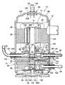
尚、上記実施例のスプリットサイクルでは、主膨張弁106(主絞り手段)と補助膨張弁109(補助絞り手段)をそれぞれ別々に構成し、絞りをそれぞれ制御するものとしたが、当該主絞り手段と補助絞り手段とを一体に構成しても構わない。この場合には、放熱器105から出た高圧冷媒を上記実施例の如く中間熱交換器107の手前で主冷媒流と補助冷媒流に分岐させずに、全て中間熱交換器107に流して冷却し、当該中間熱交換器107を通過した後に分岐させる必要がある。図11は上記二つの絞り手段を一体構造とした一実施例の絞り装置の模式図である。
In the split cycle of the above embodiment, the main expansion valve 106 (main throttle means) and the auxiliary expansion valve 109 (auxiliary throttle means) are separately configured to control the throttles respectively. And the auxiliary throttle means may be integrated. In this case, the high-pressure refrigerant discharged from the
図11において、201は補助絞り手段としての弁装置であり、202は主絞り手段としての弁装置である。即ち、中間熱交換器107から出た高圧冷媒が冷媒入口203から当該装置内に入り、そこで主流(第2の冷媒流)と補助流(第1の冷媒流)とに分岐され、第2の冷媒流は主絞り手段としての弁装置202により減圧され、蒸発器108に入り、第1の冷媒流は補助絞り手段としての弁装置201により減圧された後、中間熱交換器107に入る。弁装置202は、高圧均圧口206から導入される高圧側冷媒の圧力とスプリングにより絞り量が制御される。弁装置201は、中間均圧口204から導入される中間圧力や感温筒205を用いることにより中間熱交換器107の入口温度、若しくは、出口の冷媒温度に応じて操作される。第1の冷媒流はこの弁装置201で減圧された後、中間熱交換器107の第1の流路に入る。
In FIG. 11, 201 is a valve device as auxiliary throttle means, and 202 is a valve device as main throttle means. That is, the high-pressure refrigerant that has exited from the
本実施例では高圧側冷媒を分岐する位置が中間熱交換器107を通過したあとである点において前記実施例のスプリットサイクルと相違するが、スプリットサイクルの作用、及び当該スプリットサイクルを用いることによる効果は同一であり、本発明により性能の向上を図ることができる効果も共通して述べることができる。また、弁装置201、202への入口を別々に設けることにより、通常の(例えば、上記実施例1の)スプリットサイクルと同一の冷媒流れとすることも可能である。
This embodiment differs from the split cycle of the above embodiment in that the position where the high-pressure side refrigerant is branched after passing through the
尚、本実施例では均圧式並びに温度式絞り装置の例について一体構造とすることを説明したが、電子式膨張弁、その他の絞り手段においてもこれらの絞り手段を結合し一体構造とすることが可能である。 In the present embodiment, the example of the pressure equalization type and the temperature type throttle device has been described as being integrated. However, the electronic expansion valve and other throttle means may be combined to form an integral structure. Is possible.
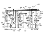
尚、本発明の冷凍装置は、上述した各実施例の装置に限らず、その他、複数の蒸発器や放熱器により回路が構成された冷凍装置であっても適用することができる。図12はその一実施例の冷凍装置のブロック図である。図12に示す冷凍装置300は冷房、暖房及び/又は給湯の混在運転を可能としたスプリットサイクル装置である。本実施例のスプリットサイクルは、圧縮手段としてのこの場合の低圧側圧縮手段301及び高圧側圧縮手段302と、利用側熱交換器としての第1の熱交換器305、第2の熱交換器306及び第3の熱交換器307と、熱源側熱交換器としての第4の熱交換器308等から構成される。
Note that the refrigeration apparatus of the present invention is not limited to the apparatuses of the above-described embodiments, but can be applied to any refrigeration apparatus in which a circuit is configured by a plurality of evaporators and radiators. FIG. 12 is a block diagram of the refrigeration apparatus of one embodiment. The
第1及び第2の熱交換器305、306は、室内を冷房或いは暖房するための熱交換器であり、各熱交換器305、306の一端に接続された配管310、311は2つに分岐され、一方の配管310A、311Aは高圧側圧縮手段302から出た高圧配管312に接続される。また、他方の配管310B、311Bは低圧側圧縮手段301の入口に接続された低圧配管313と接続される。各配管310A、310B、311A、311Bにはそれぞれ切換弁としての弁装置315、316、317、318が設けられており、運転モードに応じて開閉が制御される。各熱交換器305、306の他端はそれぞれ配管320、321を介して前記第4の熱交換器308の他端に至る高圧配管330に接続される。また、配管320には主絞り手段として主膨張弁325が設けられ、同様に配管321にも主絞り手段としての主膨張弁326が設置されている。
The first and
そして、上記弁装置315、316、第1の熱交換器305、主膨張弁325により室内を冷暖房する一つの室内ユニットが構成され、弁装置317、318、第2の熱交換器306、主膨張弁326により他の室内を冷暖房するもう一つの室内ユニットが構成される。
The
前記第3の熱交換器307は、水タンク340に貯留された水を加熱するための熱交換器であり、当該熱交換器307の一端は配管345を介して高圧側圧縮手段302の出口に至る前記高圧配管312の途中部に接続される。この配管345には高圧配管312から第3の熱交換器307への冷媒流入を制御するための弁装置346が設けられている。また、冷媒熱交換器307の他端は配管347を介して前記高圧配管330に接続される。当該配管347にも主絞り手段としての膨張弁348が設置されている。そして、第3の熱交換器307、弁装置346、膨張弁348、水タンク340等により給湯ユニットが構成される。
The third heat exchanger 307 is a heat exchanger for heating the water stored in the
一方、第4の熱交換器308は熱源側の熱交換器であり、当該熱交換器308の一端に接続された配管350は2つに分岐して、一方の配管350Aは前記高圧配管312に接続され、他方の配管350Bは前記低圧配管313に接続される。各配管350A、350Bにはそれぞれ切換弁としての弁装置355、356が設けられ、運転モードに応じて開閉が制御される。また、第4の熱交換器308の他端には前記高圧配管330が接続される。当該高圧配管330には絞り手段としての膨張弁360が設けられ、当該膨張弁360の第4の熱交換器308と反対側となる高圧配管330にはスプリットサイクルを構成する分流器370と中間熱交換器375が設けられている。
On the other hand, the
上記分流器370は、第4の熱交換器308から流出した冷媒を主回路冷媒(第2の冷媒流)と補助回路冷媒(第1の冷媒流)の二つの流れに分流するための分流手段である。そして、補助回路を構成する配管380上には、補助回路冷媒(第1の冷媒流)を中間圧に減圧するための補助絞り手段としての補助膨張弁385が設けられている。本実施例の冷凍装置では、運転モードや冷凍負荷によってスプリットサイクルを行わない場合が想定されるため、当該補助膨張弁385は配管380を流れる中間圧の冷媒量を0とすることができる全閉機能を具備したものであることが望ましい。また、その他上述した膨張弁325、326、348及び360も運転モードや負荷状態によっては一部の熱交換器を使用しない場合があるため、全閉機能を具備したものであることが好ましい。
The
前記第1の熱交換器305、第2の熱交換器306及び第4の熱交換器308は運転モードや負荷状態に応じて、蒸発器、或いは、放熱器として機能する。即ち、第1の熱交換器305を蒸発器として使用し、室内の冷房を行う場合には、高圧配管312に接続された配管310Aの弁装置315を閉じ、低圧配管313に接続された配管310Bの弁装置316を開くと共に、膨張弁325により冷媒を減圧する。これにより、分流器370にて分岐され、主回路を流れる第2の冷媒流は、当該膨張弁325により減圧され、第1の熱交換器305に入り、そこで空気と熱交換を行って蒸発し、その後、配管310B、低圧配管313を経由して低圧側圧縮手段301に流れる。
The
同様に、第2の熱交換器306を蒸発器として使用し、室内の冷房を行う場合には、高圧配管312に接続された配管311Aの弁装置317を閉じ、低圧配管313に接続された配管311Bの弁装置318を開くと共に、膨張弁326により冷媒を減圧する。これにより、分流器370にて分岐され、主回路を流れる第2の冷媒流は、当該膨張弁326により減圧され、第2の熱交換器305に入り、そこで空気と熱交換を行って蒸発し、その後、配管311B、低圧配管313を経由して低圧側圧縮手段301に流れる。
Similarly, when the
一方、第1の熱交換器305を放熱器として使用し、室内の暖房を行う場合には、高圧配管312に接続された配管310Aの弁装置315を開き、低圧配管313に接続された配管310Bの弁装置316を閉じると共に、膨張弁325を全開とする。これにより、高圧側圧縮手段302から吐出された冷媒は高圧配管312、配管310Aを経由して第1の熱交換器305に入り、そこで空気と熱交換して冷却される。その後、冷媒は膨張弁325にて減圧されずに高圧配管330に流入する。
On the other hand, when the
同様に、第2の熱交換器306を放熱器として使用し、室内の暖房を行う場合には、高圧配管312に接続された配管311Aの弁装置317を開き、低圧配管313に接続された配管311Bの弁装置318を閉じると共に、膨張弁326を全開とする。これにより、高圧側圧縮手段302から吐出された冷媒は高圧配管312、配管311Aを経由して第2の熱交換器306に入り、そこで空気と熱交換して冷却される。その後、冷媒は膨張弁326にて減圧されること無く、高圧配管330に流入する。
Similarly, when the
他方、第4の熱交換器308は、運転モードや負荷状況等に応じて外気或いは他の熱媒体から熱を汲み上げるか、若しくは、外気或いは他の熱媒体に熱を捨てるか切り換え可能である。例えば、上記第1及び第2の熱交換器305、306を蒸発器として使用し、室内を冷房する場合等、即ち、利用側熱交換器の冷房負荷が加熱負荷より大きく、熱源側熱交換器である第4の熱交換器308を放熱器として使用する場合には、高圧配管312に接続された配管350Aの弁装置355を開き、低圧配管313に接続された配管350Bの弁装置356を閉じると共に、膨張弁360を全開とする。これにより、高圧側圧縮手段302から吐出された冷媒は高圧配管312、配管350Aを経由して第4の熱交換器308に入り、そこで空気或いは熱媒体と熱交換して冷却され、高圧配管330に流入する。
On the other hand, the
また、例えば、第1及び第2の熱交換器305、306を放熱器として使用し、室内を暖房する場合等、即ち、利用側熱交換器の冷房負荷より加熱負荷が大きい場合には、第4の熱交換器308は蒸発器として使用する。この場合、高圧配管312に接続された配管350Aの弁装置355を閉じて、低圧配管313に接続された配管350Bの弁装置356を開くと共に、膨張弁360により冷媒を減圧する。これにより、高圧側配管330からの冷媒は膨張弁360で減圧され、第4の熱交換器308に入り、そこで空気或いは熱媒体と熱交換して蒸発する。その後、第4の熱交換器308から出た冷媒は、配管350B、低圧配管313を経て低圧側圧縮手段301に吸い込まれる。
Further, for example, when the first and
更に、第1及び第2の熱交換器305、306を蒸発器として使用し、第3の熱交換器307を放熱器として使用する場合や第1の熱交換器305及び第2の熱交換器306のどちらか一方を放熱器として使用し、他方を蒸発器として使用する場合等、即ち、利用側熱交換器(熱交換器305、306、307)の冷却負荷と加熱負荷とが同程度である場合には、第4の熱交換器308にて冷媒の放熱或いは蒸発を行わないものとすることも可能である。この場合には、弁装置355及び弁装置356を全閉し、同様に膨張弁360も全閉することで、第4の熱交換器308への冷媒の流入が禁止される。
Further, when the first and
尚、第4の熱交換器308において冷却された後の冷媒が流れる高圧配管330上に設置された分流器370と中間熱交換器375によるスプリットサイクルの作用効果は既に説明済みの実施例1の基本構成の場合と同じであるため説明を省略する。
The effect of the split cycle by the
他方、冷凍装置300の中間熱交換器375の流れ形式が並行流となるか、対向流となるかは運転モードに応じて異なる。即ち、利用側熱交換器(第1又は第2の熱交換器305、306)の冷房負荷が、利用側熱交換器の加熱負荷より大きく、熱源側熱交換器である第4の熱交換器308を放熱器として利用する場合には、中間熱交換器375にて第1の冷媒流と第2の冷媒流が対向流となり、冷媒の分岐は中間熱交換器375の上流側にて行われるように構成される。これにより、第1の冷媒流にて第2の冷媒流を効果的に冷却することができるので、第1の熱交換器305及び第2の熱交換器306におけるエンタルピー差を大きくでき、冷却能力の向上を図ることができる。
On the other hand, whether the flow format of the
また、利用側熱交換器(第1又は第2の熱交換器305、306)の冷房負荷が、利用側熱交換器の加熱負荷より小さい場合には、熱交換器107は中間熱交換器375にて第1の冷媒流と第2の冷媒流が平行流となる。更に、第3の熱交換器307を使用して水タンク340内の水を加熱する場合し、第1及び第2の熱交換器305、306にて室内を冷房する場合等の利用側熱交換器の冷却負荷と加熱負荷とが同程度である場合には、中間熱交換器375は使用されず、膨張弁385は閉塞される。
In addition, when the cooling load of the use side heat exchanger (first or
尚、冷媒の分岐が中間熱交換器375の上流側であるか下流側であるかは、分岐手段及び中間熱交換器の配置、並びに、運転モードにより異なるものであり、分岐手段及び中間熱交換器の配置については本実施例に限定されるものではなく、前述のように予め想定される利用形態に応じて適切に配置可能であることは言うまでもない。
Whether the refrigerant branch is upstream or downstream of the
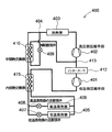
図13は本発明の更にもう一つの他の実施例のスプリットサイクル装置のブロック図である。本実施例のスプリットサイクル装置400には、異なる温度域で冷却することができる2つの蒸発器405、406が設けられている。即ち、本実施例のスプリットサイクル装置400は、圧縮手段を構成する低圧側圧縮手段401と、インタークーラ412と、2つの冷媒流を合流させる合流装置としての合流器413と、同じく圧縮手段を構成する高圧側圧縮手段402と、放熱器403と、分流手段としての分流器404と、中間熱交換器410と、内部熱交換器415と、補助絞り手段としての補助膨張弁409と、主絞り手段としての主膨張弁407と、同じく主絞り手段としての主膨張弁408と、蒸発器405、406とから構成されている。上記主膨張弁408の絞り量は、主膨張弁407の絞り量より小さくなるように制御される。従って、当該主膨張弁407で減圧された後、蒸発器405に流入して蒸発する冷媒の蒸発温度は、主膨張弁408で減圧され蒸発器406で蒸発する冷媒の蒸発温度より低くなる。
FIG. 13 is a block diagram of a split cycle apparatus according to still another embodiment of the present invention. The
中間熱交換器410は、前記各実施例で詳述した第1の冷媒流と第2の冷媒流とを熱交換させるためのものである。上記内部熱交換器415は中間熱交換器410から出た高圧側の第2の冷媒流と各蒸発器405、406から出た低圧側の第2の冷媒流を熱交換するためのものであり、当該内部熱交換器415にて、中間熱交換器410にて第1の冷媒流と熱交換して冷却された高圧側の第2の冷媒流を各蒸発器405、406から出た低圧側の第2の冷媒流にて更に冷却することができる。また、各蒸発器405、406から出た低温低圧の第2の冷媒流を高圧側の第2の冷媒流にて加熱することで、低圧側圧縮手段401に吸い込まれる第2の冷媒流の過熱度をとることができるようになる。これにより、低圧側圧縮手段401に液冷媒が吸い込まれる所謂液圧縮の発生を未然に解消できる。
The
以上の構成で、本実施例のスプリットサイクル装置400における冷媒の動作について簡単に説明する。低圧側圧縮手段401にて圧縮され、中間圧となった冷媒は、インタークーラ413にて冷却された後、高圧側圧縮手段402にて高温高圧の冷媒となる。そして、当該高圧側圧縮手段402から出た冷媒は放熱器403で放熱する。そして、放熱器403を出た冷媒は分流器404に至る。当該分流器404は上記各実施例で詳述した如く放熱器403から出た冷媒を第1の冷媒流と第2の冷媒流の二つの流れに分流するための分流手段である。当該分流器404にて分流された一方の冷媒流である第1の冷媒流は補助回路に入り、当該補助回路に設けられた補助膨張弁409にて減圧されて、中間熱交換器410にて分流器404にて分流された他方の冷媒流である第2の冷媒流と熱交換した後、圧縮手段の中間圧部に吸い込まれる。即ち、中間熱交換器410から出た第1の冷媒流は、低圧側圧縮手段401にて圧縮され、インタークーラ412にて冷却された中間圧の冷媒と合流器413で合流して、高圧側圧縮手段402に吸い込まれる。
With the above configuration, the operation of the refrigerant in the
一方、中間熱交換器410から出た第2の冷媒流は、内部熱交換器415を通過した後、更に二つの冷媒流に分流され、一方の冷媒流は主膨張弁407を経て、蒸発器405に流入して蒸発する。他方の冷媒流は主膨張弁408を経て蒸発器406に流入し、そこで蒸発する。但し、主膨張弁407と408は交互に開放され、蒸発器405と406は交互に使用される。即ち、一方の主膨張弁407或いは408が開いているときは、他方の主膨張弁408或いは407は閉じる。そして、各蒸発器405、406にてそれぞれ蒸発した冷媒は何れも内部熱交換器415を通過した後、圧縮手段の低圧部である低圧側圧縮手段401に吸い込まれるサイクルを繰り返す。
On the other hand, the second refrigerant flow coming out of the
上述の如く本実施例のスプリットサイクル装置400では、内部熱交換器415を通過して冷却された第2の冷媒流を分流して、主膨張弁407が開いている場合には当該主膨張弁407にて減圧した後、蒸発器405に流入させる。また、主膨張弁407より小さい絞り量の主膨張弁408が開いている場合には当該主膨張弁408にて減圧した後に、蒸発器406に流入させる。これにより、各蒸発器405、406では異なる温度域にて冷媒が蒸発する(蒸発器405の方が蒸発器406より低い温度域)ことになる。これにより、例えば、冷蔵と冷凍のように異なる温度域(蒸発器406が冷蔵、蒸発器405が冷凍)にて冷却することができるので、当該装置400を家庭用の冷蔵庫として使用することは勿論、商業用の冷凍装置として使用することも可能である。尚、本実施例のスプリットサイクル装置400においても本発明により、性能向上を図ることができる。
As described above, in the
(D)内部中間圧型多段圧縮式ロータリコンプレッサ
次に、本発明の圧縮手段の一実施例として、低圧側圧縮手段としての低段側の圧縮要素101と高圧側圧縮手段としての高段側の圧縮要素104とを備えた圧縮機について図14乃至図18を用いて説明する。
(D) Internal intermediate pressure type multi-stage compression rotary compressor Next, as one embodiment of the compression means of the present invention, a low-
(D−1)圧縮機の構造
図14乃至図18は、本発明の圧縮手段の一実施例のロータリコンプレッサ10をそれぞれ示している。ロータリコンプレッサ10は、二酸化炭素(CO2)を冷媒として使用する内部中間圧型多段圧縮式のロータリコンプレッサで、このロータリコンプレッサ10は鋼板から成る円筒状の密閉容器12と、この密閉容器12の内部空間の上側に配置収納された電動要素14とこの電動要素14の下側に配置され、電動要素14の回転軸16により駆動される低段側の圧縮要素101と高段側の圧縮要素104から成る回転圧縮機構部18にて構成されている。実施例のロータリコンプレッサ10の高さ寸法は220mm(外径120mm)、電動要素14の高さ寸法は約80mm(外径110mm)、回転圧縮機構部18の高さ寸法は約70mm(外径110mm)で、電動要素14と回転圧縮機構部18との間隔は約5mmとなっている。また、高段側の圧縮要素104の排除容積は低段側の圧縮要素101の排除容積よりも小さく設定されている。
(D-1) Compressor Structure FIGS. 14 to 18 show the
密閉容器12は実施例では厚さ4.5mmの鋼板より構成され、底部をオイル溜めとし、電動要素14と回転圧縮機構部18を収納する容器本体12Aと、この容器本体12Aの上部開口を閉塞する略椀状のエンドキャップ(蓋体)12Bとで構成され、且つ、このエンドキャップ12Bの上面中心には円形の取付孔12Dが形成されており、この取付孔12Dには電動要素14に電力を供給するためのターミナル(配線を省略)20が取り付けられている。
In the embodiment, the sealed
この場合、ターミナル20の周囲のエンドキャップ12Bには、座押成形によって所定曲率の段差部12Cが環状に形成されている。また、ターミナル20は電気的端子139が貫通して取り付けられた円形のガラス部20Aと、このガラス部20Aの周囲に形成され、斜め外下方に鍔状に張り出した金属製の取付部20Bとから構成されている。取付部20Bの厚さ寸法は、2.4mm±0.5mmとされている。そして、ターミナル20は、そのガラス部20Aを下側から取付孔12Dに挿入して上側に臨ませ、取付部20Bを取付孔12Dの周縁に当接させた状態でエンドキャップ12Bの取付孔12D周縁に取付部20Bを溶接することで、エンドキャップ12Bに固定されている。
In this case, the
電動要素14は、密閉容器12の上部空間の内周面に沿って環状に取り付けられたステータ22と、このステータ22の内側に若干の間隙を設けて挿入配置されたロータ24とからなる。このロータ24は中心を通り鉛直方向に延びる回転軸16に固定されている。
The
ステータ22は、ドーナッツ状の電磁鋼板を積層した積層体26と、この積層体26の歯部に直巻き(集中巻き)方式により巻装されたステータコイル28を有している。また、ロータ24もステータ22と同様に電磁鋼板の積層体30で形成され、この積層体30内に永久磁石MGを挿入して構成されている。
The
前記低段側の圧縮要素101と高段側の圧縮要素104との間には中間仕切板36が挟持されている。即ち、低段側の圧縮要素101と高段側の圧縮要素104は、中間仕切板36と、この中間仕切板36の上下に配置されたシリンダ38、シリンダ40と、この上下シリンダ38、40内を180度の位相差を有して回転軸16に設けた上下偏心部42、44に嵌合されて偏心回転する上下ローラ46、48と、この上下ローラ46、48に当接して上下シリンダ38、40内をそれぞれ低圧室側と高圧室側に区画する上下ベーン50(下側のベーンは図示せず)と、上シリンダ38の上側の開口面及び下シリンダ40の下側の開口面を閉塞して回転軸16の軸受けを兼用する支持部材としてぼ上部支持部材54及び下部支持部材56にて構成される。
An
上部支持部材54及び下部支持部材56には、吸込ポート161、162にて上下シリンダ38、40の内部とそれぞれ連通する吸込通路58、60と、凹陥した吐出消音室62、64が形成されると共に、これら両吐出消音室62、64の開口部はそれぞれカバーにより閉塞される。即ち、吐出消音室62はカバーとしての上部カバー66、吐出消音室64はカバーとしての下部カバー68にて閉塞される。
The
この場合、上部支持部材54の中央には軸受け54Aが起立形成されており、この軸受け54A内面には筒状のブッシュ122が装着されている。また、下部支持部材56の中央には軸受け56Aが貫通形成されており、この軸受け56A内面にも筒状のブッシュ123が装着されている。これらブッシュ122、123は摺動性の良い材料にて構成されており、回転軸16はこれらブッシュ122、123を介して上部支持部材54の軸受け54Aと下部支持部材56の軸受け56Aに保持される。
In this case, a bearing 54A is erected at the center of the
この場合、下部カバー68はドーナッツ状の円形鋼板から構成されており、周辺部の4カ所を主ボルト129・・によって下から下部支持部材56に固定され、吐出ポート41にて低段側の圧縮要素101の下シリンダ40内部と連通する吐出消音室64の下面開口部を閉塞する。この主ボルト129・・の先端は上部支持部材54に螺合する。下部カバー68の内周縁は下部支持部材56の軸受け56A内面より内方に突出しており、これによって、ブッシュ123の下端面は下部カバー68によって保持され、脱落が防止されている。
In this case, the
下部支持部材56は鉄系の焼結材料(若しくは鋳物でも可)により構成されており、下部カバー68を取り付ける側の面(下面)は、平面度0.1mm以下に加工された後、スチーム処理が加えられる。このスチーム処理によって下部カバー68を取り付ける側の面は酸化鉄となるため、焼結材料内部の孔が塞がれてシール性が向上する。これにより、下部カバー68と下部支持部材56間にガスケットを介設する必要が無くなる。
The
尚、吐出消音室64と密閉容器12内における上部カバー66の電動要素14側は、上下シリンダ38、40や中間仕切板36を貫通する孔である連通路63にて連通されている(図17)。この場合、連通路63の上端には中間吐出管121が立設されており、この中間吐出管121は上方の電動要素14のステータ22に巻装された相隣接するステータコイル28、28間の隙間に指向している。
The
また、上部カバー66は吐出ポート39にて高段側の圧縮要素104の上シリンダ38内部と連通する吐出消音室62の上面開口部を閉塞し、密閉容器12内を吐出消音室62と電動要素14側とに区切る。この上部カバー66は厚さ2mm以上10mm以下(実施例では最も望ましい6mmとされている)であって、前記上部支持部材54の軸受け54Aが貫通する孔が形成された略ドーナッツ状の円形鋼板から構成されており、上部支持部材54との間にガード付きの図示しないガスケットを挟み込んだ状態で、当該ガスケットを介して周辺部が4本の主ボルト78・・により、上から上部支持部材54に固定されている。この主ボルト78・・の先端は下部支持部材56に螺合する。
The
上部カバー66を係る厚さ寸法とすることで、密閉容器12内よりも高圧となる吐出消音室64の圧力に充分に耐えながら、小型化を達成し、電動要素14との絶縁距離を確保することもできるようになる。
By making the
次に、上シリンダ38の下側の開口面及び下シリンダ40の上側の開口面を閉塞する中間仕切板36内には、上シリンダ38内の吸込側に対応する位置に、外周面から内周面に至り、外周面と内周面とを連通して給油路を構成する貫通孔131が穿設されており、この貫通孔131の外周面側の封止材132を圧入して外周面側の開口を封止している。また、貫通孔131の中途部には上側に延在する連通孔133が穿設されている。
Next, in the
一方、上シリンダ38の吸込ポート161(吸込側)には中間仕切板36の連通孔133に連通する連通孔134が穿設されている。また、回転軸16内には軸中心に鉛直方向のオイル孔と、このオイル孔に連通する横方向の給油孔82、84(回転軸16の上下偏心部42、44にも形成されている)が形成されており、中間仕切板36の貫通孔131の内周面側の開口は、これらの給油孔82、84を介してオイル孔に連通している。
On the other hand, a
ここで、本実施例のロータリコンプレッサ10の密閉容器12内は中間圧となるため、2段目で高圧となる上シリンダ38内にはオイルの供給が困難となるが、中間仕切板36を係る構造としたことにより、密閉容器12内底部のオイル溜めから汲み上げられてオイル孔を上昇し、給油孔82、84から出たオイルは、中間仕切板36の貫通孔131に入り、連通孔133、134から上シリンダ38の吸込側(吸込ポート161)に供給されるようになる。
Here, since the inside of the
他方、上述の如く上下シリンダ38、40、中間仕切板36、上下支持部材54、56及び上下カバー66、68はそれぞれ4本の主ボルト78・・と主ボルト129・・にて上下から締結されるが、更に、上下シリンダ38、40、中間仕切板36、上下支持部材54、56は、これら主ボルト78、129の外側に位置する補助ボルト136、136により締結される(図17)。この補助ボルト136は上部支持部材54側から挿入され、先端は下部支持部材56に螺合している。
On the other hand, as described above, the upper and
また、この補助ボルト136は前述したベーン50の後述する案内溝70の近傍に位置している。このように補助ボルト136、136を追加して回転圧縮機構部18を一体化することで、内部が極めて高圧となることに対するシール性の確保が成されると共に、ベーン50の案内溝70の近傍を締め付けるので、後述する如くベーン50に加える高圧の背圧のリークも防止できるようになる。
The
一方、上シリンダ38内には前述したベーン50を収納する図示しない案内溝と、この案内溝の外側に位置してバネ部材としてのスプリング76を収納する収納部とが形成されており、この収納部は上記案内溝と密閉容器12(容器本体12A)側に開口している。前記スプリング76はベーン50の外側端部に当接し、常時ベーン50をローラ46側に付勢する。そして、このスプリング76の密閉容器12側の収納部内には、収納部の外側(密閉容器12側)の開口から金属製のプラグ137が圧入されて設けられ、スプリング76の抜け止めの役目を果たす。
On the other hand, in the
この場合、プラグ137の外形寸法は、それを収納部内に圧入した際に上シリンダ38が変形を起こさない程度、収納部の内径寸法よりも大きく設定されている。即ち、実施例ではプラグ137の外形寸法は、収納部の内径寸法よりも4μm〜23μm大きく設計されている。また、プラグ137の周面には当該プラグ137と収納部の内面間をシールするための図示しないOリングが取り付けられている。
In this case, the outer dimension of the
そして、この場合も冷媒としては地球環境にやさしく、可燃性および毒性等を考慮して自然冷媒である前記二酸化炭素(CO2)を使用し、潤滑油としてのオイルは、例えば鉱物油(ミネラルオイル)、アルキルベンゼン油、エーテル油、エステル油等が依存のオイルが使用される。 In this case as well, the refrigerant is environmentally friendly and uses the carbon dioxide (CO 2 ), which is a natural refrigerant in consideration of flammability and toxicity, and the oil as the lubricating oil is, for example, mineral oil (mineral oil) ), Alkylbenzene oils, ether oils, ester oils and the like are used.
密閉容器12の容器本体12Aの側面には、上部支持部材54と下部支持部材56の吸込通路58、60、吐出消音室62及び上部カバー66の上側(電動要素14の下端に略対応する位置)に対応する位置に、スリーブ141、142、143及び144がそれぞれ溶接固定されている。スリーブ141と142は上下に隣接すると共に、スリーブ143はスリーブ141の対角線上にある。また、スリーブ144はスリーブ141と略90度ずれた位置にある。
On the side surface of the container
そして、スリーブ141内には上シリンダ38に冷媒ガスを導入するための冷媒導入管92の一端が挿入接続され、この冷媒導入管92の一端は上シリンダ38の吸込通路58に連通される。この冷媒導入管92の他端は合流器146の底端に接続されている。当該合流器146の上端には、配管95及び配管100の一端が接続されている。そして、配管95の他端はインタークーラ102(図1)を経てスリーブ144内に挿入接続されて密閉容器12内に連通する。また、配管100は図1の中間熱交換器107の第1の流路を出た補助回路の配管である。
One end of a
また、スリーブ142内には下シリンダ40に冷媒ガスを導入するための冷媒導入管94の一端が挿入接続され、この冷媒導入管94の一端は下シリンダ40の吸込通路60に連通される。この冷媒導入管94の他端は、蒸発器108に接続されている(図1)。また、スリーブ143内には冷媒吐出管96が挿入接続され、この冷媒吐出管96の一端は吐出消音室62に連通される。この冷媒吐出管96の他端は放熱器105に接続されている(図1)。
Also, one end of a
また、スリーブ141、143、144の外面周囲には配管接続用のカプラが係合可能な鍔部151が形成されており、スリーブ142の内面には配管接続用の図示しないネジ溝が形成されている。これにより、スリーブ141、143、144にはロータリコンプレッサ10の製造工程における完成検査で気密実験を行う場合に試験用配管のカプラを鍔部151に容易に接続できるようになると共に、スリーブ142にはネジ溝を使用して試験用配管を容易にネジ止めできるようになる。特に、上下で隣接するスリーブ141と142は、一方のスリーブ141に鍔部151が、他方のスリーブ142にネジ溝が形成されていることで、狭い空間で試験用配管を各スリーブ141、142に接続可能となる。
Further, a
(D−2)制御
以上の構成で次にロータリコンプレッサ10を実施例1の冷凍装置を適用した場合における動作を説明する。制御装置(コントローラ)はロータリコンプレッサ10の電動要素14の回転数制御を行う。制御装置(コントローラ)によりターミナル20及び図示されない配線を介してロータ24が回転する。この回転により回転軸16と一体に設けた上下偏心部42、44に嵌合された上下ローラ46、48が上下シリンダ38、40内を偏心回転する。
(D-2) Control Next, the operation when the refrigeration apparatus of the first embodiment is applied to the
これにより、冷媒導入管94および下部支持部材56に形成された吸込通路60を経由して吸込ポート162から下シリンダ40の低圧室側に吸入された低圧(一段目吸入圧:4MPaG)の冷媒ガスは、ローラ48とベーンの動作により圧縮されて中間圧(MP1:8MPaG)となり下シリンダ40の高圧室側より吐出ポート41、下部支持部材56に形成された吐出消音室64から連通路63を経て中間吐出管121から密閉容器12内に吐出される。
As a result, the low-pressure (first-stage suction pressure: 4 MPaG) refrigerant gas sucked from the
このとき、中間吐出管121は上方の電動要素14のステータ22に巻装された相隣接するステータコイル28、28間の隙間に指向しているので、未だ比較的温度の低い冷媒ガスを電動要素14方向に積極的に供給できるようになり、電動要素14の温度上昇が抑制されるようになる。また、これによって、密閉容器12内は中間圧(MP1)となる。
At this time, since the
そして、密閉容器12内の中間圧の冷媒ガスは、スリーブ144から出て(中間吐出圧は前記MP1)配管95、インタークーラ102(図1)を経由して、合流器146に至り、ここで配管100を通る中間熱交換器107(図1)からの第1の冷媒流の冷媒と合流する。
The intermediate-pressure refrigerant gas in the sealed
合流器146の底端から流出した合流冷媒は、配管92及び上部支持部材54に形成された吸込通路58を経由して吸込ポート161から上シリンダ38の低圧室側に吸入される(二段目吸入圧MP2)。吸入された中間圧の冷媒ガスは、ローラ46とベーン50の動作により2段目の圧縮が行われて高温高圧の冷媒ガスとなる(2段目吐出圧HP:12MPaG)。高温高圧の冷媒ガスは高圧室側から吐出ポート39、上部支持部材54に形成された吐出消音室62を経由して、冷媒吐出管96に流入する。
The merged refrigerant flowing out from the bottom end of the
尚、上述した各実施例の補助回路を有する多段冷媒装置は、上記説明の権利の技術を当業者に理解できるように、実例を挙げて説明したものであり、上記各実施例に限定されるものではない。従って、発明の目的や特徴の範囲内で開示された発明の実施例を変更するものとしても構わない。 In addition, the multistage refrigerant apparatus having the auxiliary circuit of each of the above-described embodiments has been described by way of examples so that those skilled in the art can understand the technology of the right described above, and is limited to each of the above-described embodiments. It is not a thing. Accordingly, the embodiments of the disclosed invention may be modified within the scope of the object and features of the invention.
10 多段圧縮式ロータリコンプレッサ
101 低段側圧縮要素
102 インタークーラ
103 アキュムレータ
104 高段側圧縮要素
105 放熱器
106 主膨張弁(主絞り手段)
107 中間熱交換器
108 蒸発器
109 補助膨張弁(補助絞り手段)
110 分流器
146 合流器
DESCRIPTION OF
107
110
Claims (10)
前記圧縮手段の吸入圧力と吐出圧力に基づいて前記補助絞り手段を制御することにより、前記圧縮手段の中間圧部の圧力を決定することを特徴とする冷凍装置。 The refrigeration cycle is constituted by the compression means, the radiator, the auxiliary throttle means, the intermediate heat exchanger, the main throttle means, and the evaporator, and the refrigerant discharged from the radiator is divided into two flows, and the first refrigerant flow Is passed through the auxiliary throttle means to the first flow path of the intermediate heat exchanger, the second refrigerant flow is flowed to the second flow path of the intermediate heat exchanger, and then the main throttle means is passed through the By flowing through the evaporator, the intermediate heat exchanger exchanges heat between the first refrigerant flow and the second refrigerant flow, and sucks the refrigerant discharged from the evaporator into the low pressure portion of the compression means. In the refrigerating apparatus for sucking the first refrigerant flow from the intermediate heat exchanger into the intermediate pressure part of the compression means,
A refrigeration apparatus characterized in that the pressure of the intermediate pressure portion of the compression means is determined by controlling the auxiliary throttle means based on the suction pressure and discharge pressure of the compression means.
前記圧縮手段の吸入圧力と吐出圧力に基づき、前記圧縮手段の中間圧部の圧力を決定したことを特徴とする冷凍装置。 The refrigeration cycle is constituted by the compression means, the radiator, the auxiliary throttle means, the intermediate heat exchanger, the main throttle means, and the evaporator, and the refrigerant discharged from the radiator is divided into two flows, and the first refrigerant flow Is passed through the auxiliary throttle means to the first flow path of the intermediate heat exchanger, the second refrigerant flow is flowed to the second flow path of the intermediate heat exchanger, and then the main throttle means is passed through the By flowing through the evaporator, the intermediate heat exchanger exchanges heat between the first refrigerant flow and the second refrigerant flow, and sucks the refrigerant discharged from the evaporator into the low pressure portion of the compression means. In the refrigerating apparatus for sucking the first refrigerant flow from the intermediate heat exchanger into the intermediate pressure part of the compression means,
The refrigeration apparatus characterized in that the pressure of the intermediate pressure portion of the compression means is determined based on the suction pressure and the discharge pressure of the compression means.
Pint,opt=Kint,opt*GMP=Kint,opt*(Psuc*Pdis)0.5 ・・・(1)
Pint,opt=最適中間圧
Kint,opt=最適中間圧係数
GMP=高圧圧力と低圧圧力の相乗平均
Psuc=圧縮手段の吸入圧力
Pdis=圧縮手段の吐出圧力
前記補助絞り手段を制御することにより、上記数式(1)で得られる最適中間圧に前記圧縮手段の中間圧部における圧力を制御することを特徴とする冷凍装置。 The refrigeration cycle is constituted by the compression means, the radiator, the auxiliary throttle means, the intermediate heat exchanger, the main throttle means, and the evaporator, and the refrigerant discharged from the radiator is divided into two flows, and the first refrigerant flow Is passed through the auxiliary throttle means to the first flow path of the intermediate heat exchanger, the second refrigerant flow is flowed to the second flow path of the intermediate heat exchanger, and then the main throttle means is passed through the By flowing through the evaporator, the intermediate heat exchanger exchanges heat between the first refrigerant flow and the second refrigerant flow, and sucks the refrigerant discharged from the evaporator into the low pressure portion of the compression means. In the refrigerating apparatus for sucking the first refrigerant flow from the intermediate heat exchanger into the intermediate pressure part of the compression means,
Pint, opt = Kint, opt * GMP = Kint, opt * (Psuc * Pdis) 0.5 (1)
Pint, opt = Optimum intermediate pressure
Kint, opt = Optimum intermediate pressure coefficient
GMP = geometric mean of high pressure and low pressure
Psuc = Suction pressure of compression means
Pdis = discharge pressure of compression means
By controlling the auxiliary throttle means, the pressure in the intermediate pressure part of the compression means is controlled to the optimum intermediate pressure obtained by the mathematical formula (1).
Pint,opt=Kint,opt*GMP=Kint,opt*(Psuc*Pdis)0.5 ・・・(1)
Pint,opt=最適中間圧
Kint,opt=最適中間圧係数
GMP=高圧圧力と低圧圧力の相乗平均
Psuc=圧縮手段の吸入圧力
Pdis=圧縮手段の吐出圧力
前記圧縮手段の中間圧部における圧力を、上記数式(1)で得られた最適中間圧としたことを特徴とする冷凍装置。 The refrigeration cycle is constituted by the compression means, the radiator, the auxiliary throttle means, the intermediate heat exchanger, the main throttle means, and the evaporator, and the refrigerant discharged from the radiator is divided into two flows, and the first refrigerant flow Is passed through the auxiliary throttle means to the first flow path of the intermediate heat exchanger, the second refrigerant flow is flowed to the second flow path of the intermediate heat exchanger, and then the main throttle means is passed through the By flowing through the evaporator, the intermediate heat exchanger exchanges heat between the first refrigerant flow and the second refrigerant flow, and sucks the refrigerant discharged from the evaporator into the low pressure portion of the compression means. In the refrigerating apparatus for sucking the first refrigerant flow from the intermediate heat exchanger into the intermediate pressure part of the compression means,
Pint, opt = Kint, opt * GMP = Kint, opt * (Psuc * Pdis) 0.5 (1)
Pint, opt = Optimum intermediate pressure
Kint, opt = Optimum intermediate pressure coefficient
GMP = geometric mean of high pressure and low pressure
Psuc = Suction pressure of compression means
Pdis = discharge pressure of compression means
The refrigeration apparatus characterized in that the pressure in the intermediate pressure portion of the compression means is the optimum intermediate pressure obtained by the above formula (1).
前記蒸発器における冷媒の蒸発温度及び外気温度に基づいて前記補助絞り手段を制御することにより、前記圧縮手段の中間圧部の圧力を決定することを特徴とする冷凍装置。 The refrigeration cycle is constituted by the compression means, the radiator, the auxiliary throttle means, the intermediate heat exchanger, the main throttle means, and the evaporator, and the refrigerant discharged from the radiator is divided into two flows, and the first refrigerant flow Is passed through the auxiliary throttle means to the first flow path of the intermediate heat exchanger, the second refrigerant flow is flowed to the second flow path of the intermediate heat exchanger, and then the main throttle means is passed through the By flowing through the evaporator, the intermediate heat exchanger exchanges heat between the first refrigerant flow and the second refrigerant flow, and sucks the refrigerant discharged from the evaporator into the low pressure portion of the compression means. In the refrigerating apparatus for sucking the first refrigerant flow from the intermediate heat exchanger into the intermediate pressure part of the compression means,
The refrigeration apparatus characterized in that the pressure of the intermediate pressure part of the compression means is determined by controlling the auxiliary throttle means based on the evaporation temperature and the outside air temperature of the refrigerant in the evaporator.
前記蒸発器における冷媒の蒸発温度及び外気温度に基づき、前記圧縮手段の中間圧部の圧力を決定したことを特徴とする冷凍装置。 The refrigeration cycle is constituted by the compression means, the radiator, the auxiliary throttle means, the intermediate heat exchanger, the main throttle means, and the evaporator, and the refrigerant discharged from the radiator is divided into two flows, and the first refrigerant flow Is passed through the auxiliary throttle means to the first flow path of the intermediate heat exchanger, the second refrigerant flow is flowed to the second flow path of the intermediate heat exchanger, and then the main throttle means is passed through the By flowing through the evaporator, the intermediate heat exchanger exchanges heat between the first refrigerant flow and the second refrigerant flow, and sucks the refrigerant discharged from the evaporator into the low pressure portion of the compression means. In the refrigerating apparatus for sucking the first refrigerant flow from the intermediate heat exchanger into the intermediate pressure part of the compression means,
The refrigeration apparatus characterized in that the pressure of the intermediate pressure portion of the compression means is determined based on the evaporation temperature and the outside air temperature of the refrigerant in the evaporator.
前記中間熱交換器から出た前記第2の冷媒流の温度、又は、前記中間熱交換器から出た前記第1の冷媒流の温度を所定の値に制御することを特徴とする冷凍装置。 The refrigeration cycle is constituted by the compression means, the radiator, the auxiliary throttle means, the intermediate heat exchanger, the main throttle means, and the evaporator, and the refrigerant discharged from the radiator is divided into two flows, and the first refrigerant flow Is passed through the auxiliary throttle means to the first flow path of the intermediate heat exchanger, the second refrigerant flow is flowed to the second flow path of the intermediate heat exchanger, and then the main throttle means is passed through the By flowing through the evaporator, the intermediate heat exchanger exchanges heat between the first refrigerant flow and the second refrigerant flow, and sucks the refrigerant discharged from the evaporator into the low pressure portion of the compression means. In the refrigerating apparatus for sucking the first refrigerant flow from the intermediate heat exchanger into the intermediate pressure part of the compression means,
The refrigeration apparatus characterized by controlling the temperature of the second refrigerant flow coming out of the intermediate heat exchanger or the temperature of the first refrigerant flow coming out of the intermediate heat exchanger to a predetermined value.
Applications Claiming Priority (2)
| Application Number | Priority Date | Filing Date | Title |
|---|---|---|---|
| US11/066,560 US7631510B2 (en) | 2005-02-28 | 2005-02-28 | Multi-stage refrigeration system including sub-cycle control characteristics |
| US11/066,560 | 2005-02-28 |
Publications (2)
| Publication Number | Publication Date |
|---|---|
| JP2006242557A true JP2006242557A (en) | 2006-09-14 |
| JP4820180B2 JP4820180B2 (en) | 2011-11-24 |
Family
ID=36297374
Family Applications (1)
| Application Number | Title | Priority Date | Filing Date |
|---|---|---|---|
| JP2006027260A Expired - Lifetime JP4820180B2 (en) | 2005-02-28 | 2006-02-03 | Refrigeration equipment |
Country Status (5)
| Country | Link |
|---|---|
| US (1) | US7631510B2 (en) |
| EP (1) | EP1703229B1 (en) |
| JP (1) | JP4820180B2 (en) |
| CN (1) | CN1847750A (en) |
| NO (1) | NO337218B1 (en) |
Cited By (29)
| Publication number | Priority date | Publication date | Assignee | Title |
|---|---|---|---|---|
| JP2007232263A (en) * | 2006-02-28 | 2007-09-13 | Daikin Ind Ltd | Refrigeration equipment |
| JP2008213830A (en) * | 2007-02-28 | 2008-09-18 | Valeo Systemes Thermiques | Air conditioning device equipped with an electric expansion valve |
| JP2008241125A (en) * | 2007-03-27 | 2008-10-09 | Sanyo Electric Co Ltd | Refrigeration equipment |
| JP2008249209A (en) * | 2007-03-29 | 2008-10-16 | Sanyo Electric Co Ltd | Refrigerating device |
| JP2009097847A (en) * | 2007-09-28 | 2009-05-07 | Daikin Ind Ltd | Refrigeration equipment |
| WO2009072379A1 (en) * | 2007-12-07 | 2009-06-11 | Mitsubishi Heavy Industries, Ltd. | Refrigerant circuit |
| WO2009096372A1 (en) * | 2008-01-30 | 2009-08-06 | Daikin Industries, Ltd. | Refrigeration device |
| JP2009192164A (en) * | 2008-02-15 | 2009-08-27 | Mitsubishi Electric Corp | Refrigeration equipment |
| JP2009198019A (en) * | 2008-02-19 | 2009-09-03 | Sanyo Electric Co Ltd | Heat pump type hot water supply device |
| JP2009204235A (en) * | 2008-02-28 | 2009-09-10 | Sanyo Electric Co Ltd | Heat pump type water heater |
| WO2009136581A1 (en) * | 2008-05-08 | 2009-11-12 | ダイキン工業株式会社 | Refrigeration device |
| JP2010210133A (en) * | 2009-03-10 | 2010-09-24 | Sanyo Electric Co Ltd | Refrigerating cycle device |
| JP2011052866A (en) * | 2009-08-31 | 2011-03-17 | Sanyo Electric Co Ltd | Refrigerating cycle device |
| JP2011512509A (en) * | 2008-02-19 | 2011-04-21 | キャリア コーポレイション | Refrigerant vapor compression system |
| JP2011133206A (en) * | 2009-12-25 | 2011-07-07 | Sanyo Electric Co Ltd | Refrigerating apparatus |
| JP2011133207A (en) * | 2009-12-25 | 2011-07-07 | Sanyo Electric Co Ltd | Refrigerating apparatus |
| JP2011208894A (en) * | 2010-03-30 | 2011-10-20 | Sanyo Electric Co Ltd | Refrigerating device |
| JP2011242056A (en) * | 2010-05-18 | 2011-12-01 | Mitsubishi Electric Corp | Refrigeration device |
| JP2012013290A (en) * | 2010-06-30 | 2012-01-19 | Sanyo Electric Co Ltd | Refrigerating device |
| JP2012149844A (en) * | 2011-01-20 | 2012-08-09 | Mitsubishi Electric Corp | Refrigerating cycle device |
| WO2013030896A1 (en) * | 2011-09-01 | 2013-03-07 | 三菱電機株式会社 | Refrigeration cycle device |
| JP2014029257A (en) * | 2012-07-04 | 2014-02-13 | Fuji Electric Co Ltd | Refrigerant circuit device |
| JP2014159950A (en) * | 2014-04-24 | 2014-09-04 | Sanyo Electric Co Ltd | Freezer |
| US8997508B2 (en) | 2009-12-25 | 2015-04-07 | Panasonic Intellectual Property Management Co., Ltd. | Refrigerating apparatus |
| CN110701810A (en) * | 2019-10-29 | 2020-01-17 | 中机国能炼化工程有限公司 | Injection supercharging two-stage series connection supercooling double-temperature-zone refrigerating system and application |
| CN110806033A (en) * | 2019-10-29 | 2020-02-18 | 中机国能炼化工程有限公司 | Critical CO is striden in coupling of two subcooler series connection expander2Dual-temperature zone system and application |
| WO2022249566A1 (en) * | 2021-05-27 | 2022-12-01 | 三菱重工サーマルシステムズ株式会社 | Multi-stage compression refrigeration device |
| JP2023005307A (en) * | 2021-06-28 | 2023-01-18 | パナソニックIpマネジメント株式会社 | compressor |
| WO2026018579A1 (en) * | 2024-07-16 | 2026-01-22 | ダイキン工業株式会社 | Transportation-use refrigeration device and transportation-use container |
Families Citing this family (39)
| Publication number | Priority date | Publication date | Assignee | Title |
|---|---|---|---|---|
| EP1571337B1 (en) * | 2004-03-05 | 2007-11-28 | Corac Group plc | Multi-stage No-oil Gas Compressor |
| JP2006084115A (en) * | 2004-09-16 | 2006-03-30 | Matsushita Electric Ind Co Ltd | Heat pump water heater |
| JP5040104B2 (en) * | 2005-11-30 | 2012-10-03 | ダイキン工業株式会社 | Refrigeration equipment |
| JP2007263431A (en) * | 2006-03-28 | 2007-10-11 | Sanyo Electric Co Ltd | Manufacturing method of transient critical refrigerating cycle apparatus |
| WO2008054380A2 (en) * | 2006-10-27 | 2008-05-08 | Carrier Corporation | Economized refrigeration cycle with expander |
| JP2009133585A (en) * | 2007-11-30 | 2009-06-18 | Daikin Ind Ltd | Refrigeration equipment |
| CN101878403B (en) * | 2007-11-30 | 2013-03-20 | 大金工业株式会社 | Freezing apparatus |
| JP5029326B2 (en) * | 2007-11-30 | 2012-09-19 | ダイキン工業株式会社 | Refrigeration equipment |
| JP5003439B2 (en) * | 2007-11-30 | 2012-08-15 | ダイキン工業株式会社 | Refrigeration equipment |
| JP5003440B2 (en) * | 2007-11-30 | 2012-08-15 | ダイキン工業株式会社 | Refrigeration equipment |
| KR101570235B1 (en) * | 2007-12-31 | 2015-11-18 | 존슨 컨트롤스 테크놀러지 컴퍼니 | Method and system for rotor cooling |
| US9994751B2 (en) * | 2008-04-30 | 2018-06-12 | Honeywell International Inc. | Absorption refrigeration cycles using a LGWP refrigerant |
| US20110232306A1 (en) * | 2008-04-30 | 2011-09-29 | Honeywell International Inc. | Absorption refrigeration cycles using a lgwp refrigerant |
| JP5120056B2 (en) * | 2008-05-02 | 2013-01-16 | ダイキン工業株式会社 | Refrigeration equipment |
| JP5181813B2 (en) * | 2008-05-02 | 2013-04-10 | ダイキン工業株式会社 | Refrigeration equipment |
| ITTV20080140A1 (en) * | 2008-11-04 | 2010-05-05 | Enex Srl | REFRIGERATOR SYSTEM WITH ALTERNATIVE COMPRESSOR AND ECONOMISER. |
| WO2010137120A1 (en) * | 2009-05-26 | 2010-12-02 | 三菱電機株式会社 | Heat pump type hot water supply device |
| ES2869237T3 (en) * | 2010-04-27 | 2021-10-25 | Mitsubishi Electric Corp | Refrigeration cycle apparatus |
| US9989279B2 (en) | 2010-04-29 | 2018-06-05 | Carrier Corporation | Refrigerant vapor compression system with intercooler |
| JP5287831B2 (en) * | 2010-10-29 | 2013-09-11 | 株式会社デンソー | Two-stage boost refrigeration cycle |
| KR101249898B1 (en) * | 2011-01-21 | 2013-04-09 | 엘지전자 주식회사 | Heat pump |
| US10119059B2 (en) | 2011-04-11 | 2018-11-06 | Jun Cui | Thermoelastic cooling |
| US10266034B2 (en) * | 2011-06-16 | 2019-04-23 | Hamilton Sundstrand Corporation | Heat pump for supplemental heat |
| JP5375919B2 (en) * | 2011-09-30 | 2013-12-25 | ダイキン工業株式会社 | heat pump |
| KR101873595B1 (en) | 2012-01-10 | 2018-07-02 | 엘지전자 주식회사 | A cascade heat pump and a driving method for the same |
| US10018385B2 (en) * | 2012-03-27 | 2018-07-10 | University Of Maryland, College Park | Solid-state heating or cooling systems, devices, and methods |
| CN104121724B (en) * | 2013-04-27 | 2018-10-26 | 浙江三花汽车零部件有限公司 | A kind of air-conditioning system and a kind of heat exchanger |
| CN105865071B (en) * | 2015-01-22 | 2018-09-25 | Tcl空调器(中山)有限公司 | Air conditioning system |
| DE102015214705A1 (en) * | 2015-07-31 | 2017-02-02 | Technische Universität Dresden | Apparatus and method for performing a cold vapor process |
| DE102016201485B3 (en) | 2016-02-01 | 2017-04-13 | Fraunhofer-Gesellschaft zur Förderung der angewandten Forschung e.V. | Arrangement and method for wavefront analysis |
| ES2900352T3 (en) * | 2017-09-07 | 2022-03-16 | Mitsubishi Electric Corp | air conditioning device |
| CN111023610B (en) * | 2018-10-10 | 2021-11-05 | 南通华信中央空调有限公司 | Heat pump system and method for operating the same |
| CN111380240A (en) * | 2018-12-28 | 2020-07-07 | 青岛海尔空调电子有限公司 | Air conditioning system with two-stage compression |
| GB2599867A (en) * | 2019-06-14 | 2022-04-13 | Li Huayu | Reverse single working medium steam combined cycle |
| WO2021047125A1 (en) * | 2019-09-10 | 2021-03-18 | 李华玉 | Reverse single-working-medium steam combined cycle |
| CN110887265B (en) * | 2019-11-25 | 2021-01-12 | 珠海格力电器股份有限公司 | Internal circulation superposition heat pump system, control method and heat pump dryer |
| GR20210100429A (en) * | 2021-06-28 | 2023-01-10 | Στεργιος Κωνσταντινου Ραβανης | Heat pump's multi compression method |
| CN114484908B (en) * | 2022-01-28 | 2023-06-13 | 澳柯玛股份有限公司 | Two-stage compressor refrigerating system and control method thereof |
| CN116007242A (en) * | 2022-12-14 | 2023-04-25 | 华涧新能源科技(上海)有限公司 | Energy storage heat management system using intermediate heat exchange of flash tank |
Citations (6)
| Publication number | Priority date | Publication date | Assignee | Title |
|---|---|---|---|---|
| JPH04363554A (en) * | 1991-06-10 | 1992-12-16 | Hitachi Ltd | Controlling method for blower of air-cool type refrigerator |
| JPH1038392A (en) * | 1996-07-23 | 1998-02-13 | Sanyo Electric Co Ltd | Speed control device for blower for condenser |
| JPH11344265A (en) * | 1998-06-02 | 1999-12-14 | Mitsubishi Heavy Ind Ltd | Turbo freezer of multistage compression system |
| JP2001133058A (en) * | 1999-11-05 | 2001-05-18 | Matsushita Electric Ind Co Ltd | Refrigeration cycle device |
| JP2001153476A (en) * | 1999-11-30 | 2001-06-08 | Sanyo Electric Co Ltd | Refrigerating plant |
| JP2002228275A (en) * | 2001-01-31 | 2002-08-14 | Mitsubishi Heavy Ind Ltd | Supercritical steam compression refrigerating cycle |
Family Cites Families (6)
| Publication number | Priority date | Publication date | Assignee | Title |
|---|---|---|---|---|
| US4918942A (en) * | 1989-10-11 | 1990-04-24 | General Electric Company | Refrigeration system with dual evaporators and suction line heating |
| US6321564B1 (en) * | 1999-03-15 | 2001-11-27 | Denso Corporation | Refrigerant cycle system with expansion energy recovery |
| US6568198B1 (en) | 1999-09-24 | 2003-05-27 | Sanyo Electric Co., Ltd. | Multi-stage compression refrigerating device |
| JP2002327690A (en) | 2001-04-27 | 2002-11-15 | Daikin Ind Ltd | Two-stage compressor |
| TW568996B (en) * | 2001-11-19 | 2004-01-01 | Sanyo Electric Co | Defroster of refrigerant circuit and rotary compressor for refrigerant circuit |
| US7424807B2 (en) * | 2003-06-11 | 2008-09-16 | Carrier Corporation | Supercritical pressure regulation of economized refrigeration system by use of an interstage accumulator |
-
2005
- 2005-02-28 US US11/066,560 patent/US7631510B2/en active Active
-
2006
- 2006-02-03 JP JP2006027260A patent/JP4820180B2/en not_active Expired - Lifetime
- 2006-02-23 EP EP06003741.3A patent/EP1703229B1/en not_active Expired - Lifetime
- 2006-02-24 NO NO20060909A patent/NO337218B1/en unknown
- 2006-02-28 CN CNA2006100794406A patent/CN1847750A/en active Pending
Patent Citations (6)
| Publication number | Priority date | Publication date | Assignee | Title |
|---|---|---|---|---|
| JPH04363554A (en) * | 1991-06-10 | 1992-12-16 | Hitachi Ltd | Controlling method for blower of air-cool type refrigerator |
| JPH1038392A (en) * | 1996-07-23 | 1998-02-13 | Sanyo Electric Co Ltd | Speed control device for blower for condenser |
| JPH11344265A (en) * | 1998-06-02 | 1999-12-14 | Mitsubishi Heavy Ind Ltd | Turbo freezer of multistage compression system |
| JP2001133058A (en) * | 1999-11-05 | 2001-05-18 | Matsushita Electric Ind Co Ltd | Refrigeration cycle device |
| JP2001153476A (en) * | 1999-11-30 | 2001-06-08 | Sanyo Electric Co Ltd | Refrigerating plant |
| JP2002228275A (en) * | 2001-01-31 | 2002-08-14 | Mitsubishi Heavy Ind Ltd | Supercritical steam compression refrigerating cycle |
Cited By (40)
| Publication number | Priority date | Publication date | Assignee | Title |
|---|---|---|---|---|
| WO2007105440A1 (en) * | 2006-02-28 | 2007-09-20 | Daikin Industries, Ltd. | Refrigeration device |
| JP2007232263A (en) * | 2006-02-28 | 2007-09-13 | Daikin Ind Ltd | Refrigeration equipment |
| JP2008213830A (en) * | 2007-02-28 | 2008-09-18 | Valeo Systemes Thermiques | Air conditioning device equipped with an electric expansion valve |
| JP2008241125A (en) * | 2007-03-27 | 2008-10-09 | Sanyo Electric Co Ltd | Refrigeration equipment |
| JP2008249209A (en) * | 2007-03-29 | 2008-10-16 | Sanyo Electric Co Ltd | Refrigerating device |
| JP2009097847A (en) * | 2007-09-28 | 2009-05-07 | Daikin Ind Ltd | Refrigeration equipment |
| JP2012141131A (en) * | 2007-09-28 | 2012-07-26 | Daikin Industries Ltd | Refrigerating apparatus |
| WO2009072379A1 (en) * | 2007-12-07 | 2009-06-11 | Mitsubishi Heavy Industries, Ltd. | Refrigerant circuit |
| AU2009210093B2 (en) * | 2008-01-30 | 2011-09-15 | Daikin Industries, Ltd. | Refrigeration apparatus |
| WO2009096372A1 (en) * | 2008-01-30 | 2009-08-06 | Daikin Industries, Ltd. | Refrigeration device |
| JP2009180428A (en) * | 2008-01-30 | 2009-08-13 | Daikin Ind Ltd | Refrigeration equipment |
| JP2009192164A (en) * | 2008-02-15 | 2009-08-27 | Mitsubishi Electric Corp | Refrigeration equipment |
| JP2009198019A (en) * | 2008-02-19 | 2009-09-03 | Sanyo Electric Co Ltd | Heat pump type hot water supply device |
| JP2011512509A (en) * | 2008-02-19 | 2011-04-21 | キャリア コーポレイション | Refrigerant vapor compression system |
| JP2009204235A (en) * | 2008-02-28 | 2009-09-10 | Sanyo Electric Co Ltd | Heat pump type water heater |
| JP2009270776A (en) * | 2008-05-08 | 2009-11-19 | Daikin Ind Ltd | Refrigerating device |
| WO2009136581A1 (en) * | 2008-05-08 | 2009-11-12 | ダイキン工業株式会社 | Refrigeration device |
| US8863545B2 (en) | 2008-05-08 | 2014-10-21 | Daikin Industries, Ltd. | Refrigeration apparatus |
| JP2010210133A (en) * | 2009-03-10 | 2010-09-24 | Sanyo Electric Co Ltd | Refrigerating cycle device |
| JP2011052866A (en) * | 2009-08-31 | 2011-03-17 | Sanyo Electric Co Ltd | Refrigerating cycle device |
| JP2011133206A (en) * | 2009-12-25 | 2011-07-07 | Sanyo Electric Co Ltd | Refrigerating apparatus |
| JP2011133207A (en) * | 2009-12-25 | 2011-07-07 | Sanyo Electric Co Ltd | Refrigerating apparatus |
| US8997508B2 (en) | 2009-12-25 | 2015-04-07 | Panasonic Intellectual Property Management Co., Ltd. | Refrigerating apparatus |
| JP2011208894A (en) * | 2010-03-30 | 2011-10-20 | Sanyo Electric Co Ltd | Refrigerating device |
| JP2011242056A (en) * | 2010-05-18 | 2011-12-01 | Mitsubishi Electric Corp | Refrigeration device |
| JP2012013290A (en) * | 2010-06-30 | 2012-01-19 | Sanyo Electric Co Ltd | Refrigerating device |
| JP2012149844A (en) * | 2011-01-20 | 2012-08-09 | Mitsubishi Electric Corp | Refrigerating cycle device |
| WO2013030896A1 (en) * | 2011-09-01 | 2013-03-07 | 三菱電機株式会社 | Refrigeration cycle device |
| US9395105B2 (en) | 2011-09-01 | 2016-07-19 | Mitsubishi Electric Corporation | Refrigeration cycle device |
| JP2014029257A (en) * | 2012-07-04 | 2014-02-13 | Fuji Electric Co Ltd | Refrigerant circuit device |
| JP2014159950A (en) * | 2014-04-24 | 2014-09-04 | Sanyo Electric Co Ltd | Freezer |
| CN110806033A (en) * | 2019-10-29 | 2020-02-18 | 中机国能炼化工程有限公司 | Critical CO is striden in coupling of two subcooler series connection expander2Dual-temperature zone system and application |
| CN110701810A (en) * | 2019-10-29 | 2020-01-17 | 中机国能炼化工程有限公司 | Injection supercharging two-stage series connection supercooling double-temperature-zone refrigerating system and application |
| WO2022249566A1 (en) * | 2021-05-27 | 2022-12-01 | 三菱重工サーマルシステムズ株式会社 | Multi-stage compression refrigeration device |
| JP2022181837A (en) * | 2021-05-27 | 2022-12-08 | 三菱重工サーマルシステムズ株式会社 | Multistage compression refrigeration device |
| JP7674153B2 (en) | 2021-05-27 | 2025-05-09 | 三菱重工サーマルシステムズ株式会社 | Multi-stage compression refrigeration unit |
| EP4350256A4 (en) * | 2021-05-27 | 2025-06-04 | Mitsubishi Heavy Industries Thermal Systems, Ltd. | MULTI-STAGE COMPRESSION REFRIGERATION DEVICE |
| JP2023005307A (en) * | 2021-06-28 | 2023-01-18 | パナソニックIpマネジメント株式会社 | compressor |
| WO2026018579A1 (en) * | 2024-07-16 | 2026-01-22 | ダイキン工業株式会社 | Transportation-use refrigeration device and transportation-use container |
| JP2026013152A (en) * | 2024-07-16 | 2026-01-28 | ダイキン工業株式会社 | Transport refrigeration units and transport containers |
Also Published As
| Publication number | Publication date |
|---|---|
| US7631510B2 (en) | 2009-12-15 |
| CN1847750A (en) | 2006-10-18 |
| EP1703229A3 (en) | 2010-03-24 |
| JP4820180B2 (en) | 2011-11-24 |
| NO20060909L (en) | 2006-08-29 |
| US20060191288A1 (en) | 2006-08-31 |
| EP1703229B1 (en) | 2014-08-27 |
| EP1703229A2 (en) | 2006-09-20 |
| NO337218B1 (en) | 2016-02-15 |
Similar Documents
| Publication | Publication Date | Title |
|---|---|---|
| JP4820180B2 (en) | Refrigeration equipment | |
| KR101280155B1 (en) | Heat pump device, two-stage compressor, and method of operating heat pump device | |
| AU2009323588A1 (en) | Refrigerating apparatus | |
| WO2016201623A1 (en) | Refrigeration cycle device | |
| JP2011133209A (en) | Refrigerating apparatus | |
| US20090282849A1 (en) | Refrigeration System | |
| KR101250084B1 (en) | Two-stage compressor and heat pump apparatus | |
| KR101332478B1 (en) | Freezing device | |
| KR101220663B1 (en) | Freezer | |
| JP2013155972A (en) | Refrigeration device | |
| JP2011133210A (en) | Refrigerating apparatus | |
| JP2011133208A (en) | Refrigerating apparatus | |
| JP2014159950A (en) | Freezer | |
| JP5502460B2 (en) | Refrigeration equipment | |
| JP6370593B2 (en) | Oil-cooled multistage screw compressor and oil draining method thereof | |
| JP2014163624A (en) | Turbo refrigerator | |
| JP2007232230A (en) | Refrigeration equipment | |
| KR20130096859A (en) | Compressor and air conditioner | |
| JP4738219B2 (en) | Refrigeration equipment | |
| JP2006275494A (en) | Refrigerating device, refrigerator and compressor | |
| JP3469845B2 (en) | Multi-stage compression refrigeration equipment | |
| JP2018179353A (en) | Refrigeration cycle device, rotary compressor | |
| JP2006275035A (en) | Refrigerating device, refrigerator and compressor | |
| JP2007147228A (en) | Refrigeration equipment | |
| JP2011137556A (en) | Refrigerating apparatus |
Legal Events
| Date | Code | Title | Description |
|---|---|---|---|
| A621 | Written request for application examination |
Free format text: JAPANESE INTERMEDIATE CODE: A621 Effective date: 20081215 |
|
| A977 | Report on retrieval |
Free format text: JAPANESE INTERMEDIATE CODE: A971007 Effective date: 20100823 |
|
| A131 | Notification of reasons for refusal |
Free format text: JAPANESE INTERMEDIATE CODE: A131 Effective date: 20100831 |
|
| A521 | Request for written amendment filed |
Free format text: JAPANESE INTERMEDIATE CODE: A523 Effective date: 20101019 |
|
| A131 | Notification of reasons for refusal |
Free format text: JAPANESE INTERMEDIATE CODE: A131 Effective date: 20110301 |
|
| A521 | Request for written amendment filed |
Free format text: JAPANESE INTERMEDIATE CODE: A523 Effective date: 20110414 |
|
| TRDD | Decision of grant or rejection written | ||
| A01 | Written decision to grant a patent or to grant a registration (utility model) |
Free format text: JAPANESE INTERMEDIATE CODE: A01 Effective date: 20110830 |
|
| A01 | Written decision to grant a patent or to grant a registration (utility model) |
Free format text: JAPANESE INTERMEDIATE CODE: A01 |
|
| A61 | First payment of annual fees (during grant procedure) |
Free format text: JAPANESE INTERMEDIATE CODE: A61 Effective date: 20110902 |
|
| FPAY | Renewal fee payment (event date is renewal date of database) |
Free format text: PAYMENT UNTIL: 20140909 Year of fee payment: 3 |
|
| R150 | Certificate of patent or registration of utility model |
Ref document number: 4820180 Country of ref document: JP Free format text: JAPANESE INTERMEDIATE CODE: R150 Free format text: JAPANESE INTERMEDIATE CODE: R150 |
|
| R250 | Receipt of annual fees |
Free format text: JAPANESE INTERMEDIATE CODE: R250 |
|
| R250 | Receipt of annual fees |
Free format text: JAPANESE INTERMEDIATE CODE: R250 |
|
| R250 | Receipt of annual fees |
Free format text: JAPANESE INTERMEDIATE CODE: R250 |
|
| R250 | Receipt of annual fees |
Free format text: JAPANESE INTERMEDIATE CODE: R250 |
|
| R250 | Receipt of annual fees |
Free format text: JAPANESE INTERMEDIATE CODE: R250 |
|
| R250 | Receipt of annual fees |
Free format text: JAPANESE INTERMEDIATE CODE: R250 |
|
| R250 | Receipt of annual fees |
Free format text: JAPANESE INTERMEDIATE CODE: R250 |
|
| R250 | Receipt of annual fees |
Free format text: JAPANESE INTERMEDIATE CODE: R250 |
|
| R250 | Receipt of annual fees |
Free format text: JAPANESE INTERMEDIATE CODE: R250 |
|
| R250 | Receipt of annual fees |
Free format text: JAPANESE INTERMEDIATE CODE: R250 |
|
| R250 | Receipt of annual fees |
Free format text: JAPANESE INTERMEDIATE CODE: R250 |
|
| R250 | Receipt of annual fees |
Free format text: JAPANESE INTERMEDIATE CODE: R250 |
|
| EXPY | Cancellation because of completion of term |