JP2006242559A - 一体形缶型燃焼器 - Google Patents
一体形缶型燃焼器 Download PDFInfo
- Publication number
- JP2006242559A JP2006242559A JP2006052424A JP2006052424A JP2006242559A JP 2006242559 A JP2006242559 A JP 2006242559A JP 2006052424 A JP2006052424 A JP 2006052424A JP 2006052424 A JP2006052424 A JP 2006052424A JP 2006242559 A JP2006242559 A JP 2006242559A
- Authority
- JP
- Japan
- Prior art keywords
- combustor
- transition piece
- sleeve
- turbine
- flow
- Prior art date
- Legal status (The legal status is an assumption and is not a legal conclusion. Google has not performed a legal analysis and makes no representation as to the accuracy of the status listed.)
- Granted
Links
Images


Classifications
-
- F—MECHANICAL ENGINEERING; LIGHTING; HEATING; WEAPONS; BLASTING
- F23—COMBUSTION APPARATUS; COMBUSTION PROCESSES
- F23R—GENERATING COMBUSTION PRODUCTS OF HIGH PRESSURE OR HIGH VELOCITY, e.g. GAS-TURBINE COMBUSTION CHAMBERS
- F23R3/00—Continuous combustion chambers using liquid or gaseous fuel
- F23R3/02—Continuous combustion chambers using liquid or gaseous fuel characterised by the air-flow or gas-flow configuration
- F23R3/16—Continuous combustion chambers using liquid or gaseous fuel characterised by the air-flow or gas-flow configuration with devices inside the flame tube or the combustion chamber to influence the air or gas flow
- F23R3/18—Flame stabilising means, e.g. flame holders for after-burners of jet-propulsion plants
- F23R3/22—Flame stabilising means, e.g. flame holders for after-burners of jet-propulsion plants movable, e.g. to an inoperative position; adjustable, e.g. self-adjusting
-
- F—MECHANICAL ENGINEERING; LIGHTING; HEATING; WEAPONS; BLASTING
- F23—COMBUSTION APPARATUS; COMBUSTION PROCESSES
- F23R—GENERATING COMBUSTION PRODUCTS OF HIGH PRESSURE OR HIGH VELOCITY, e.g. GAS-TURBINE COMBUSTION CHAMBERS
- F23R3/00—Continuous combustion chambers using liquid or gaseous fuel
- F23R3/42—Continuous combustion chambers using liquid or gaseous fuel characterised by the arrangement or form of the flame tubes or combustion chambers
- F23R3/60—Support structures; Attaching or mounting means
-
- F—MECHANICAL ENGINEERING; LIGHTING; HEATING; WEAPONS; BLASTING
- F23—COMBUSTION APPARATUS; COMBUSTION PROCESSES
- F23R—GENERATING COMBUSTION PRODUCTS OF HIGH PRESSURE OR HIGH VELOCITY, e.g. GAS-TURBINE COMBUSTION CHAMBERS
- F23R3/00—Continuous combustion chambers using liquid or gaseous fuel
- F23R3/42—Continuous combustion chambers using liquid or gaseous fuel characterised by the arrangement or form of the flame tubes or combustion chambers
- F23R3/44—Combustion chambers comprising a single tubular flame tube within a tubular casing
-
- F—MECHANICAL ENGINEERING; LIGHTING; HEATING; WEAPONS; BLASTING
- F23—COMBUSTION APPARATUS; COMBUSTION PROCESSES
- F23R—GENERATING COMBUSTION PRODUCTS OF HIGH PRESSURE OR HIGH VELOCITY, e.g. GAS-TURBINE COMBUSTION CHAMBERS
- F23R3/00—Continuous combustion chambers using liquid or gaseous fuel
- F23R3/42—Continuous combustion chambers using liquid or gaseous fuel characterised by the arrangement or form of the flame tubes or combustion chambers
- F23R3/46—Combustion chambers comprising an annular arrangement of several essentially tubular flame tubes within a common annular casing or within individual casings
Landscapes
- Engineering & Computer Science (AREA)
- Chemical & Material Sciences (AREA)
- Combustion & Propulsion (AREA)
- Mechanical Engineering (AREA)
- General Engineering & Computer Science (AREA)
- Turbine Rotor Nozzle Sealing (AREA)
Abstract
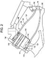
【解決手段】本缶型燃焼器は、シングルピースの移行部品を使用して燃焼器ヘッドエンドからタービン入口まで直接移行する移行部品を含む。例示的な実施形態では、移行部品には接合部がない。
【選択図】 図2
Description
11 吐出空気
14 燃焼器
16 タービンセクション
18 燃焼室
20 移行部品
22 コネクタ
24 ライナー
28 第2のフロースリーブ(燃焼器フロースリーブ)
29 第1のフロースリーブ(インピンジメントスリーブ)
30 第2のフローアニュラス
31 第1のフローアニュラス
32
34 円形キャップ
36 エンドカバー36
38 燃料ノズル
40 前方圧力ケーシング
42 後方圧力ケーシング
100 燃焼器ヘッドエンド
102 移行部品後端部
103 後方支持ラグ
110 フラシ−ル
111 ピストンリング
112 突出部
113 キー溝
120 シングルピースの移行部品
122 前方スリーブ
124 冷却フローアニュラス
128 後方フレーム
129 インピンジメントスリーブ
134 円形キャップ
136 エンドカバー
138 燃料ノズル
140 スロット
142 取付けブラケット
152 取付けピン
Claims (10)
- シングルピースの移行部品(120)を使用して燃焼器ヘッドエンド(100)からタービン入口まで直接移行する移行部品(120)を含むことを特徴とする産業用タービンの缶型燃焼器。
- 前記移行部品(120)には接合部がないことを特徴とする請求項1記載の缶型燃焼器。
- 前記移行部品(120)を囲むインピンジメントスリーブ(129)をさらに含み、
前記インピンジメントスリーブ(129)は、該インピンジメントスリーブ(129)の周辺部の周りに形成された複数の冷却孔を有し、圧縮機吐出空気(11)からの冷却空気を該インピンジメントスリーブ(129)と前記移行部品(120)との間のフローアニュラス(124)内に導くようにしたことを特徴とする請求項1記載の缶型燃焼器。 - 前記インピンジメントスリーブ(129)が、シングルピースのスリーブを使用して燃焼器前方スリーブ(122)から前記移行部品(120)の後方フレーム(128)まで直接移行することを特徴とする請求項3記載の缶型燃焼器。
- 前記移行部品(120)の後端部に配置された取付けブラケット(142)をさらに含み、
前記取付けブラケットが、それを貫通して延びて前記移行部品(120)のヘッドエンド(100)における横方向運動を可能にする取付けピン(152)を受ける細長いスロット(140)を有することを特徴とする請求項1記載の缶型燃焼器。 - 前記ブラケット(142)が、該ブラケット(142)の両側面に配置された1対の細長いスロット(140)を含むことを特徴とする請求項1記載の缶型燃焼器。
- キャップ(34、134)の外表面(114)に取付けられたフラシ−ル(110)をさらに含むことを特徴とする請求項1記載の缶型燃焼器。
- 前記フラシ−ル(110)が、前記移行部品(120)のヘッドエンド(100)と係合するようになっていることを特徴とする請求項7記載の缶型燃焼器。
- 前記キャップ(134)が、前記燃焼器のヘッドエンド(100)においてエンドカバー(136)に固定取付けされていることを特徴とする請求項7記載の缶型燃焼器。
- 前記移行部品(120)に固定取付けされ、キー突出部とタービンフレーム内のキー溝(113)とを使用して組立て時に前記移行部品(120)をタービンに対して位置決めする前方スリーブ(122)をさらに含むことを特徴とする請求項7記載の缶型燃焼器。
Applications Claiming Priority (2)
| Application Number | Priority Date | Filing Date | Title |
|---|---|---|---|
| US10/906,688 | 2005-03-02 | ||
| US10/906,688 US7082766B1 (en) | 2005-03-02 | 2005-03-02 | One-piece can combustor |
Publications (3)
| Publication Number | Publication Date |
|---|---|
| JP2006242559A true JP2006242559A (ja) | 2006-09-14 |
| JP2006242559A5 JP2006242559A5 (ja) | 2009-04-09 |
| JP4694387B2 JP4694387B2 (ja) | 2011-06-08 |
Family
ID=36293366
Family Applications (1)
| Application Number | Title | Priority Date | Filing Date |
|---|---|---|---|
| JP2006052424A Expired - Fee Related JP4694387B2 (ja) | 2005-03-02 | 2006-02-28 | 一体形缶型燃焼器 |
Country Status (6)
| Country | Link |
|---|---|
| US (1) | US7082766B1 (ja) |
| EP (1) | EP1705427B1 (ja) |
| JP (1) | JP4694387B2 (ja) |
| KR (1) | KR101240072B1 (ja) |
| CN (1) | CN1828140B (ja) |
| DE (1) | DE602006007507D1 (ja) |
Cited By (12)
| Publication number | Priority date | Publication date | Assignee | Title |
|---|---|---|---|---|
| JP2009047409A (ja) * | 2007-08-14 | 2009-03-05 | General Electric Co <Ge> | ガスタービンにおける燃焼ライナ止め具 |
| WO2010038505A1 (ja) * | 2008-10-01 | 2010-04-08 | 三菱重工業株式会社 | 燃焼器接続構造、燃焼器尾筒、燃焼器尾筒の設計方法、およびガスタービン |
| JP2010084704A (ja) * | 2008-10-01 | 2010-04-15 | Mitsubishi Heavy Ind Ltd | 燃焼器接続構造およびガスタービン |
| JP2010159745A (ja) * | 2009-01-06 | 2010-07-22 | General Electric Co <Ge> | 燃焼器移行部片用の冷却装置 |
| JP2010190216A (ja) * | 2009-02-17 | 2010-09-02 | General Electric Co <Ge> | 熱伝達表面増強機構を有する一体形缶型燃焼器 |
| JP2011226481A (ja) * | 2010-04-19 | 2011-11-10 | General Electric Co <Ge> | トランジションダクト界面における燃焼器ライナ冷却及びその関連する方法 |
| JP2013170814A (ja) * | 2012-02-20 | 2013-09-02 | General Electric Co <Ge> | 燃焼ライナガイドストッパ及び燃焼器を組み立てる方法 |
| JP2013213655A (ja) * | 2012-04-03 | 2013-10-17 | General Electric Co <Ge> | 非円形ヘッドエンドを有する燃焼器 |
| JP2013227973A (ja) * | 2012-04-24 | 2013-11-07 | General Electric Co <Ge> | 遷移ピースを含む燃焼システムおよび鋳造超合金を使用した形成方法 |
| JP2014181894A (ja) * | 2013-03-18 | 2014-09-29 | General Electric Co <Ge> | ガスタービンの燃焼モジュール用フロースリーブ |
| JP2022159047A (ja) * | 2021-03-31 | 2022-10-17 | ゼネラル・エレクトリック・カンパニイ | 後流エナジャイザを備えた燃焼器 |
| US11946645B2 (en) | 2022-07-11 | 2024-04-02 | Rolls-Royce Plc | Combustor casing component for a gas turbine engine |
Families Citing this family (67)
| Publication number | Priority date | Publication date | Assignee | Title |
|---|---|---|---|---|
| JP2005171795A (ja) * | 2003-12-09 | 2005-06-30 | Mitsubishi Heavy Ind Ltd | ガスタービン燃焼装置 |
| US7010921B2 (en) * | 2004-06-01 | 2006-03-14 | General Electric Company | Method and apparatus for cooling combustor liner and transition piece of a gas turbine |
| US8769963B2 (en) * | 2007-01-30 | 2014-07-08 | Siemens Energy, Inc. | Low leakage spring clip/ring combinations for gas turbine engine |
| GB2449267A (en) * | 2007-05-15 | 2008-11-19 | Alstom Technology Ltd | Cool diffusion flame combustion |
| JP5010521B2 (ja) * | 2008-03-28 | 2012-08-29 | 三菱重工業株式会社 | 燃焼器尾筒案内治具及びガスタービンの燃焼器の取り外し方法、並びに製造方法 |
| US9038396B2 (en) * | 2008-04-08 | 2015-05-26 | General Electric Company | Cooling apparatus for combustor transition piece |
| US20090249791A1 (en) * | 2008-04-08 | 2009-10-08 | General Electric Company | Transition piece impingement sleeve and method of assembly |
| US8096133B2 (en) * | 2008-05-13 | 2012-01-17 | General Electric Company | Method and apparatus for cooling and dilution tuning a gas turbine combustor liner and transition piece interface |
| US8087228B2 (en) * | 2008-09-11 | 2012-01-03 | General Electric Company | Segmented combustor cap |
| US9822649B2 (en) * | 2008-11-12 | 2017-11-21 | General Electric Company | Integrated combustor and stage 1 nozzle in a gas turbine and method |
| US20100170257A1 (en) * | 2009-01-08 | 2010-07-08 | General Electric Company | Cooling a one-piece can combustor and related method |
| US7926283B2 (en) * | 2009-02-26 | 2011-04-19 | General Electric Company | Gas turbine combustion system cooling arrangement |
| US8438856B2 (en) | 2009-03-02 | 2013-05-14 | General Electric Company | Effusion cooled one-piece can combustor |
| US8528336B2 (en) * | 2009-03-30 | 2013-09-10 | General Electric Company | Fuel nozzle spring support for shifting a natural frequency |
| US20100257863A1 (en) * | 2009-04-13 | 2010-10-14 | General Electric Company | Combined convection/effusion cooled one-piece can combustor |
| US8516822B2 (en) * | 2010-03-02 | 2013-08-27 | General Electric Company | Angled vanes in combustor flow sleeve |
| US8307655B2 (en) | 2010-05-20 | 2012-11-13 | General Electric Company | System for cooling turbine combustor transition piece |
| GB201011854D0 (en) | 2010-07-14 | 2010-09-01 | Isis Innovation | Vane assembly for an axial flow turbine |
| US20120186269A1 (en) * | 2011-01-25 | 2012-07-26 | General Electric Company | Support between transition piece and impingement sleeve in combustor |
| US9249679B2 (en) | 2011-03-15 | 2016-02-02 | General Electric Company | Impingement sleeve and methods for designing and forming impingement sleeve |
| US8887508B2 (en) * | 2011-03-15 | 2014-11-18 | General Electric Company | Impingement sleeve and methods for designing and forming impingement sleeve |
| US8997501B2 (en) * | 2011-06-02 | 2015-04-07 | General Electric Company | System for mounting combustor transition piece to frame of gas turbine engine |
| US8966910B2 (en) * | 2011-06-21 | 2015-03-03 | General Electric Company | Methods and systems for cooling a transition nozzle |
| US8915087B2 (en) | 2011-06-21 | 2014-12-23 | General Electric Company | Methods and systems for transferring heat from a transition nozzle |
| US8650852B2 (en) * | 2011-07-05 | 2014-02-18 | General Electric Company | Support assembly for transition duct in turbine system |
| US8448450B2 (en) * | 2011-07-05 | 2013-05-28 | General Electric Company | Support assembly for transition duct in turbine system |
| US9103551B2 (en) | 2011-08-01 | 2015-08-11 | General Electric Company | Combustor leaf seal arrangement |
| EP2742291B1 (en) * | 2011-08-11 | 2020-07-08 | General Electric Company | System for injecting fuel in a gas turbine engine |
| EP2852735B1 (de) * | 2011-10-24 | 2016-04-27 | Alstom Technology Ltd | Gasturbine |
| JP6029274B2 (ja) * | 2011-11-10 | 2016-11-24 | 三菱日立パワーシステムズ株式会社 | シール組立体、及びこれを備えたガスタービン |
| US9188340B2 (en) * | 2011-11-18 | 2015-11-17 | General Electric Company | Gas turbine combustor endcover with adjustable flow restrictor and related method |
| US9291063B2 (en) | 2012-02-29 | 2016-03-22 | Siemens Energy, Inc. | Mid-section of a can-annular gas turbine engine with an improved rotation of air flow from the compressor to the turbine |
| US20130305739A1 (en) * | 2012-05-18 | 2013-11-21 | General Electric Company | Fuel nozzle cap |
| US9657949B2 (en) * | 2012-10-15 | 2017-05-23 | Pratt & Whitney Canada Corp. | Combustor skin assembly for gas turbine engine |
| US9322556B2 (en) | 2013-03-18 | 2016-04-26 | General Electric Company | Flow sleeve assembly for a combustion module of a gas turbine combustor |
| US9316396B2 (en) | 2013-03-18 | 2016-04-19 | General Electric Company | Hot gas path duct for a combustor of a gas turbine |
| US10436445B2 (en) | 2013-03-18 | 2019-10-08 | General Electric Company | Assembly for controlling clearance between a liner and stationary nozzle within a gas turbine |
| US9383104B2 (en) | 2013-03-18 | 2016-07-05 | General Electric Company | Continuous combustion liner for a combustor of a gas turbine |
| US9400114B2 (en) | 2013-03-18 | 2016-07-26 | General Electric Company | Combustor support assembly for mounting a combustion module of a gas turbine |
| US9631812B2 (en) | 2013-03-18 | 2017-04-25 | General Electric Company | Support frame and method for assembly of a combustion module of a gas turbine |
| US9316155B2 (en) | 2013-03-18 | 2016-04-19 | General Electric Company | System for providing fuel to a combustor |
| CN104234859B (zh) * | 2013-06-07 | 2016-08-31 | 常州兰翔机械有限责任公司 | 一种燃气涡轮起动机用燃油盖的制造方法 |
| US11732892B2 (en) | 2013-08-14 | 2023-08-22 | General Electric Company | Gas turbomachine diffuser assembly with radial flow splitters |
| FR3022613B1 (fr) * | 2014-06-24 | 2019-04-19 | Safran Helicopter Engines | Bossage pour chambre de combustion. |
| EP3002519B1 (en) | 2014-09-30 | 2020-05-27 | Ansaldo Energia Switzerland AG | Combustor arrangement with fastening system for combustor parts |
| CN104595926A (zh) * | 2015-01-23 | 2015-05-06 | 北京华清燃气轮机与煤气化联合循环工程技术有限公司 | 热通道部件一体燃烧室 |
| US20160281992A1 (en) * | 2015-03-24 | 2016-09-29 | General Electric Company | Injection boss for a unibody combustor |
| US9945295B2 (en) * | 2015-06-01 | 2018-04-17 | United Technologies Corporation | Composite piston ring seal for axially and circumferentially translating ducts |
| US10197278B2 (en) | 2015-09-02 | 2019-02-05 | General Electric Company | Combustor assembly for a turbine engine |
| US10371383B2 (en) * | 2017-01-27 | 2019-08-06 | General Electric Company | Unitary flow path structure |
| KR101984396B1 (ko) | 2017-09-29 | 2019-05-30 | 두산중공업 주식회사 | 트랜지션 피스, 이를 포함하는 연소기 및 가스 터빈 |
| KR102049042B1 (ko) | 2017-10-27 | 2019-11-26 | 두산중공업 주식회사 | 연료 노즐 조립체, 이를 포함하는 연소기 및 가스 터빈 |
| KR102011903B1 (ko) | 2017-10-27 | 2019-08-19 | 두산중공업 주식회사 | 연료 노즐, 이를 포함하는 연소기 및 가스 터빈 |
| KR102046455B1 (ko) | 2017-10-30 | 2019-11-19 | 두산중공업 주식회사 | 연료 노즐, 이를 포함하는 연소기 및 가스 터빈 |
| KR102019091B1 (ko) | 2017-10-31 | 2019-11-04 | 두산중공업 주식회사 | 연료 노즐 조립체, 이를 포함하는 연소기 및 가스 터빈 |
| KR102047368B1 (ko) | 2017-10-31 | 2019-11-21 | 두산중공업 주식회사 | 연료 노즐, 이를 포함하는 연소기 및 가스 터빈 |
| KR102021129B1 (ko) | 2017-10-31 | 2019-11-04 | 두산중공업 주식회사 | 연료 노즐, 이를 포함하는 연소기 및 가스 터빈 |
| KR20190048905A (ko) | 2017-10-31 | 2019-05-09 | 두산중공업 주식회사 | 연료 노즐, 이를 포함하는 연소기 및 가스 터빈 |
| KR102064295B1 (ko) | 2017-10-31 | 2020-01-09 | 두산중공업 주식회사 | 연료 노즐, 이를 포함하는 연소기 및 가스 터빈 |
| KR102047369B1 (ko) | 2017-11-14 | 2019-11-21 | 두산중공업 주식회사 | 연료 노즐, 이를 포함하는 연소기 및 가스 터빈 |
| CN108131399B (zh) * | 2017-11-20 | 2019-06-28 | 北京动力机械研究所 | 一种发动机轴承座冷却结构 |
| KR102142140B1 (ko) | 2018-09-17 | 2020-08-06 | 두산중공업 주식회사 | 연료 노즐, 이를 포함하는 연소기 및 가스 터빈 |
| US11248797B2 (en) * | 2018-11-02 | 2022-02-15 | Chromalloy Gas Turbine Llc | Axial stop configuration for a combustion liner |
| US11377970B2 (en) | 2018-11-02 | 2022-07-05 | Chromalloy Gas Turbine Llc | System and method for providing compressed air to a gas turbine combustor |
| KR102226740B1 (ko) | 2020-01-02 | 2021-03-11 | 두산중공업 주식회사 | 연료 노즐, 이를 포함하는 연소기 및 가스 터빈 |
| US11371709B2 (en) | 2020-06-30 | 2022-06-28 | General Electric Company | Combustor air flow path |
| KR102460672B1 (ko) | 2021-01-06 | 2022-10-27 | 두산에너빌리티 주식회사 | 연료 노즐, 연료 노즐 모듈 및 이를 포함하는 연소기 |
Citations (2)
| Publication number | Priority date | Publication date | Assignee | Title |
|---|---|---|---|---|
| JPS62168932A (ja) * | 1986-01-20 | 1987-07-25 | Hitachi Ltd | ガスタ−ビン燃焼器 |
| JP2003201863A (ja) * | 2001-10-29 | 2003-07-18 | Mitsubishi Heavy Ind Ltd | 燃焼器及びこれを備えたガスタービン |
Family Cites Families (19)
| Publication number | Priority date | Publication date | Assignee | Title |
|---|---|---|---|---|
| GB1112131A (en) * | 1965-08-19 | 1968-05-01 | Lucas Industries Ltd | Gas turbine engine combustion apparatus |
| US4297842A (en) * | 1980-01-21 | 1981-11-03 | General Electric Company | NOx suppressant stationary gas turbine combustor |
| US5237813A (en) * | 1992-08-21 | 1993-08-24 | Allied-Signal Inc. | Annular combustor with outer transition liner cooling |
| GB2328011A (en) | 1997-08-05 | 1999-02-10 | Europ Gas Turbines Ltd | Combustor for gas or liquid fuelled turbine |
| JPH1183017A (ja) * | 1997-09-08 | 1999-03-26 | Mitsubishi Heavy Ind Ltd | ガスタービン用燃焼器 |
| US6098397A (en) * | 1998-06-08 | 2000-08-08 | Caterpillar Inc. | Combustor for a low-emissions gas turbine engine |
| US6494044B1 (en) * | 1999-11-19 | 2002-12-17 | General Electric Company | Aerodynamic devices for enhancing sidepanel cooling on an impingement cooled transition duct and related method |
| US6735950B1 (en) * | 2000-03-31 | 2004-05-18 | General Electric Company | Combustor dome plate and method of making the same |
| US6334310B1 (en) | 2000-06-02 | 2002-01-01 | General Electric Company | Fracture resistant support structure for a hula seal in a turbine combustor and related method |
| US6442946B1 (en) * | 2000-11-14 | 2002-09-03 | Power Systems Mfg., Llc | Three degrees of freedom aft mounting system for gas turbine transition duct |
| US6543233B2 (en) * | 2001-02-09 | 2003-04-08 | General Electric Company | Slot cooled combustor liner |
| US6606861B2 (en) * | 2001-02-26 | 2003-08-19 | United Technologies Corporation | Low emissions combustor for a gas turbine engine |
| JP2002317650A (ja) * | 2001-04-24 | 2002-10-31 | Mitsubishi Heavy Ind Ltd | ガスタービン燃焼器 |
| US6513331B1 (en) * | 2001-08-21 | 2003-02-04 | General Electric Company | Preferential multihole combustor liner |
| EP1288574A1 (de) * | 2001-09-03 | 2003-03-05 | Siemens Aktiengesellschaft | Brennkammeranordnung |
| US6751961B2 (en) * | 2002-05-14 | 2004-06-22 | United Technologies Corporation | Bulkhead panel for use in a combustion chamber of a gas turbine engine |
| EP1413831A1 (de) * | 2002-10-21 | 2004-04-28 | Siemens Aktiengesellschaft | Ringbrennkammern für eine Gasturbine und Gasturbine |
| EP1426558A3 (en) * | 2002-11-22 | 2005-02-09 | General Electric Company | Gas turbine transition piece with dimpled surface and cooling method for such a transition piece |
| US6895761B2 (en) * | 2002-12-20 | 2005-05-24 | General Electric Company | Mounting assembly for the aft end of a ceramic matrix composite liner in a gas turbine engine combustor |
-
2005
- 2005-03-02 US US10/906,688 patent/US7082766B1/en not_active Expired - Lifetime
-
2006
- 2006-02-27 EP EP06251027A patent/EP1705427B1/en not_active Expired - Lifetime
- 2006-02-27 DE DE602006007507T patent/DE602006007507D1/de not_active Expired - Lifetime
- 2006-02-28 KR KR1020060019711A patent/KR101240072B1/ko not_active Expired - Fee Related
- 2006-02-28 JP JP2006052424A patent/JP4694387B2/ja not_active Expired - Fee Related
- 2006-03-02 CN CN2006100594081A patent/CN1828140B/zh not_active Expired - Fee Related
Patent Citations (2)
| Publication number | Priority date | Publication date | Assignee | Title |
|---|---|---|---|---|
| JPS62168932A (ja) * | 1986-01-20 | 1987-07-25 | Hitachi Ltd | ガスタ−ビン燃焼器 |
| JP2003201863A (ja) * | 2001-10-29 | 2003-07-18 | Mitsubishi Heavy Ind Ltd | 燃焼器及びこれを備えたガスタービン |
Cited By (14)
| Publication number | Priority date | Publication date | Assignee | Title |
|---|---|---|---|---|
| JP2009047409A (ja) * | 2007-08-14 | 2009-03-05 | General Electric Co <Ge> | ガスタービンにおける燃焼ライナ止め具 |
| US8448451B2 (en) | 2008-10-01 | 2013-05-28 | Mitsubishi Heavy Industries, Ltd. | Height ratios for a transition piece of a combustor |
| WO2010038505A1 (ja) * | 2008-10-01 | 2010-04-08 | 三菱重工業株式会社 | 燃焼器接続構造、燃焼器尾筒、燃焼器尾筒の設計方法、およびガスタービン |
| JP2010084704A (ja) * | 2008-10-01 | 2010-04-15 | Mitsubishi Heavy Ind Ltd | 燃焼器接続構造およびガスタービン |
| EP2955446A1 (en) | 2008-10-01 | 2015-12-16 | Mitsubishi Hitachi Power Systems, Ltd. | Designing method of combustor transition piece |
| JP2010159745A (ja) * | 2009-01-06 | 2010-07-22 | General Electric Co <Ge> | 燃焼器移行部片用の冷却装置 |
| JP2010190216A (ja) * | 2009-02-17 | 2010-09-02 | General Electric Co <Ge> | 熱伝達表面増強機構を有する一体形缶型燃焼器 |
| JP2011226481A (ja) * | 2010-04-19 | 2011-11-10 | General Electric Co <Ge> | トランジションダクト界面における燃焼器ライナ冷却及びその関連する方法 |
| JP2013170814A (ja) * | 2012-02-20 | 2013-09-02 | General Electric Co <Ge> | 燃焼ライナガイドストッパ及び燃焼器を組み立てる方法 |
| JP2013213655A (ja) * | 2012-04-03 | 2013-10-17 | General Electric Co <Ge> | 非円形ヘッドエンドを有する燃焼器 |
| JP2013227973A (ja) * | 2012-04-24 | 2013-11-07 | General Electric Co <Ge> | 遷移ピースを含む燃焼システムおよび鋳造超合金を使用した形成方法 |
| JP2014181894A (ja) * | 2013-03-18 | 2014-09-29 | General Electric Co <Ge> | ガスタービンの燃焼モジュール用フロースリーブ |
| JP2022159047A (ja) * | 2021-03-31 | 2022-10-17 | ゼネラル・エレクトリック・カンパニイ | 後流エナジャイザを備えた燃焼器 |
| US11946645B2 (en) | 2022-07-11 | 2024-04-02 | Rolls-Royce Plc | Combustor casing component for a gas turbine engine |
Also Published As
| Publication number | Publication date |
|---|---|
| KR20060096319A (ko) | 2006-09-11 |
| EP1705427A1 (en) | 2006-09-27 |
| KR101240072B1 (ko) | 2013-03-06 |
| CN1828140A (zh) | 2006-09-06 |
| EP1705427B1 (en) | 2009-07-01 |
| CN1828140B (zh) | 2011-11-23 |
| DE602006007507D1 (de) | 2009-08-13 |
| JP4694387B2 (ja) | 2011-06-08 |
| US7082766B1 (en) | 2006-08-01 |
Similar Documents
| Publication | Publication Date | Title |
|---|---|---|
| JP4694387B2 (ja) | 一体形缶型燃焼器 | |
| US7975487B2 (en) | Combustor assembly for gas turbine engine | |
| US7010921B2 (en) | Method and apparatus for cooling combustor liner and transition piece of a gas turbine | |
| US7594401B1 (en) | Combustor seal having multiple cooling fluid pathways | |
| CN102678335B (zh) | 紊流化后端衬套组件 | |
| JP4675071B2 (ja) | 改良型デフレクタプレートを有するガスタービンエンジンの燃焼器ドーム組立体 | |
| US20090120093A1 (en) | Turbulated aft-end liner assembly and cooling method | |
| EP2642078B1 (en) | System and method for recirculating a hot gas flowing through a gas turbine | |
| JP2001289062A (ja) | ガスタービン燃焼器の壁面冷却構造 | |
| JP2006234377A (ja) | ガスタービン燃料ノズルを冷却するための方法及び装置 | |
| JP2013185813A (ja) | ガスタービンのための燃料ノズルおよび燃焼器 | |
| US9127842B2 (en) | Burner, operating method and assembly method | |
| US20110239654A1 (en) | Angled seal cooling system | |
| CN103423769A (zh) | 燃料喷嘴帽 | |
| US20100300107A1 (en) | Method and flow sleeve profile reduction to extend combustor liner life | |
| US10508813B2 (en) | Gas turbine combustor cross fire tube assembly with opening restricting member and guide plates | |
| JP5718796B2 (ja) | シール部材を備えたガスタービン燃焼器 | |
| EP3372795A1 (en) | Transition seal system and corresponding method for coolling the transition seal system | |
| KR101842746B1 (ko) | 가스터빈의 트랜지션피스와 터빈의 연결장치 | |
| JPH0343536B2 (ja) |
Legal Events
| Date | Code | Title | Description |
|---|---|---|---|
| A521 | Request for written amendment filed |
Free format text: JAPANESE INTERMEDIATE CODE: A523 Effective date: 20090224 |
|
| A621 | Written request for application examination |
Free format text: JAPANESE INTERMEDIATE CODE: A621 Effective date: 20090224 |
|
| RD02 | Notification of acceptance of power of attorney |
Free format text: JAPANESE INTERMEDIATE CODE: A7422 Effective date: 20110105 |
|
| RD04 | Notification of resignation of power of attorney |
Free format text: JAPANESE INTERMEDIATE CODE: A7424 Effective date: 20110105 |
|
| TRDD | Decision of grant or rejection written | ||
| A01 | Written decision to grant a patent or to grant a registration (utility model) |
Free format text: JAPANESE INTERMEDIATE CODE: A01 Effective date: 20110125 |
|
| A01 | Written decision to grant a patent or to grant a registration (utility model) |
Free format text: JAPANESE INTERMEDIATE CODE: A01 |
|
| A61 | First payment of annual fees (during grant procedure) |
Free format text: JAPANESE INTERMEDIATE CODE: A61 Effective date: 20110223 |
|
| FPAY | Renewal fee payment (event date is renewal date of database) |
Free format text: PAYMENT UNTIL: 20140304 Year of fee payment: 3 |
|
| R150 | Certificate of patent or registration of utility model |
Ref document number: 4694387 Country of ref document: JP Free format text: JAPANESE INTERMEDIATE CODE: R150 Free format text: JAPANESE INTERMEDIATE CODE: R150 |
|
| R250 | Receipt of annual fees |
Free format text: JAPANESE INTERMEDIATE CODE: R250 |
|
| R250 | Receipt of annual fees |
Free format text: JAPANESE INTERMEDIATE CODE: R250 |
|
| R250 | Receipt of annual fees |
Free format text: JAPANESE INTERMEDIATE CODE: R250 |
|
| R250 | Receipt of annual fees |
Free format text: JAPANESE INTERMEDIATE CODE: R250 |
|
| R250 | Receipt of annual fees |
Free format text: JAPANESE INTERMEDIATE CODE: R250 |
|
| R250 | Receipt of annual fees |
Free format text: JAPANESE INTERMEDIATE CODE: R250 |
|
| R250 | Receipt of annual fees |
Free format text: JAPANESE INTERMEDIATE CODE: R250 |
|
| R250 | Receipt of annual fees |
Free format text: JAPANESE INTERMEDIATE CODE: R250 |
|
| R250 | Receipt of annual fees |
Free format text: JAPANESE INTERMEDIATE CODE: R250 |
|
| LAPS | Cancellation because of no payment of annual fees |