JP2006242573A - Water meter - Google Patents
Water meter Download PDFInfo
- Publication number
- JP2006242573A JP2006242573A JP2005054229A JP2005054229A JP2006242573A JP 2006242573 A JP2006242573 A JP 2006242573A JP 2005054229 A JP2005054229 A JP 2005054229A JP 2005054229 A JP2005054229 A JP 2005054229A JP 2006242573 A JP2006242573 A JP 2006242573A
- Authority
- JP
- Japan
- Prior art keywords
- water
- impeller
- rotation
- unit
- permanent magnet
- Prior art date
- Legal status (The legal status is an assumption and is not a legal conclusion. Google has not performed a legal analysis and makes no representation as to the accuracy of the status listed.)
- Pending
Links
Images


Landscapes
- Measuring Volume Flow (AREA)
- Arrangements For Transmission Of Measured Signals (AREA)
Abstract
【課題】羽根車の回転を磁気センサで検出し積算することにより小流量域でも器差を小さくでき、かつ既設のアナログ出力機能を持つ水道メータが接続されているいかなる検針盤にも接続が可能な水道メータを提供すること。
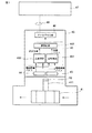
【解決手段】羽根車41の回転方向と直交する位置で回転永久磁石42が形成され、水通路の外壁面であって、回転永久磁石42に近接して磁気センサ43、44を配設し、磁気センサ43からの電磁誘導パルスを回転検出部451によって得られた計量パルスを、積算計算部453で計算し、この積算値を、1桁づつ10進数の電気出力に変換したアナログ出力を得るアナログ出力部46とを備えている。
【選択図】 図1[PROBLEMS] To reduce the instrumental error even in a small flow rate range by detecting the rotation of the impeller with a magnetic sensor and integrating it, and can be connected to any meter reading board to which an existing water meter with an analog output function is connected. Provide a good water meter.
A rotating permanent magnet is formed at a position orthogonal to the rotational direction of an impeller 41, magnetic sensors 43 and 44 are disposed on the outer wall surface of the water passage in the vicinity of the rotating permanent magnet, Analog which obtains the analog output which calculated the measurement pulse which electromagnetic induction pulse from magnetic sensor 43 was obtained by rotation detection part 451 in integration calculation part 453, and converted this integration value into the decimal number electric output by one digit And an output unit 46.
[Selection] Figure 1
Description
本発明は、アナログ出力部を持ち、需要家における水道水の使用量を検針する際に使用する電子式水道メータに関する。 The present invention relates to an electronic water meter that has an analog output unit and is used when metering the amount of tap water used by consumers.
図9は特許文献1に開示されていて、高精度な定電流源等を使用しなくても正確な計量ができることを目的として開発された使用量検針装置(水道使用量検針盤)9に対してケーブル10により電気的に接続して使用する水道メータの概略構成を説明するための図である。
FIG. 9 discloses a usage meter reading device (water usage meter reading board) 9 disclosed in
ここで、図9の水道メータについて説明する前に、前述の検針盤9について説明する。 検針盤9は、定電流源を有する検針装置と水道等の使用量に応じた抵抗値を出力する使用量メータとを信号線を介して接続し、定電流源から使用量メータに電流を供給したときの前記使用量メータの抵抗値に応じて現れる検針電圧に基づいて前記使用量の検針を行うものであって、次のような構成を備えている。
Here, before explaining the water meter of FIG. 9, the above-described
すなわち、定電流源からの電流の供給により基準電圧を発生する基準抵抗と、演算増幅器の入出力端子間に複数の比較用抵抗を接続し、これら比較用抵抗の選択制御により前記基準電圧を可変増幅して比較用電圧として出力する差動増幅回路と、検針電圧と前記比較用電圧とを比較するコンパレータと、このコンパレータによる比較結果に応じて前記差動増幅回路の比較用抵抗を選択制御し、比較用電圧を前記検針電圧に相当する電圧値に可変増幅したときの可変増幅度から前記使用量を算出する検針制御部とを具備したものである。 In other words, a reference resistor that generates a reference voltage by supplying a current from a constant current source and a plurality of comparison resistors are connected between the input and output terminals of the operational amplifier, and the reference voltage can be varied by selecting and controlling these comparison resistors. A differential amplifier circuit that amplifies and outputs as a comparison voltage, a comparator that compares the meter reading voltage and the comparison voltage, and a comparison resistor of the differential amplifier circuit is selectively controlled according to the comparison result by the comparator. And a meter-reading control unit that calculates the amount of use from a variable amplification degree when the comparison voltage is variably amplified to a voltage value corresponding to the meter-reading voltage.
このような手段を備えたことにより、水道メータの抵抗に定電流iを流したときに生じる検出電圧vkと基準電圧vhを可変増幅した比較電圧vhとを比較し、この比較結果から検針電圧vkに相当する基準電圧の可変増幅度から使用量を算出する構成としたので、定電流値11の定電流iが変動したとしてもこの変動に応じて基準電圧が変動することになり、これにより定電流の変動を相殺することができる。従って、定電流源として高精度のものでなくても正確な使用量が算出でき、さらに水道メータによる検針電圧vkと比較用電圧との比較結果から使用量が求められるので、A/D変換回路は不要となってA/D変換回路における誤差は無くなり、かつ検針制御部における機能も簡単となる。
By providing such means, the detection voltage vk generated when the constant current i flows through the resistance of the water meter is compared with the comparison voltage vh obtained by variably amplifying the reference voltage vh. Therefore, even if the constant current i of the constant
次に、以上述べた検針盤9に接続される水道メータについて、図9を参照して説明するが、この水道メータは電圧変換または電流変換のアナログ出力部を持つものである。
Next, a water meter connected to the
図9では、水道管路内に配設し、水道水の使用量に比例して回転する羽根車1の回転軸上端に接した下部ギア列2の回転によりに駆動用永久磁石3を回転する。駆動用永久磁石3の回転に合わせて受動用永久磁石4が回転することにより受動用永久磁石4に取り付けられた上部ギア列5が回転し、回転レジスタ6を動かして積算を行う。回転レジスタ6に取り付けられた接点7と基板8の接点7の位置により10進数のアナログ出力の切り替えを行う。なお、受動用永久磁石4、上部ギア列5、回転レジスタ6、接点7、基板8は、水道水が流れる流路とは隔離された容器内に配設されている。
In FIG. 9, the driving
以上述べた特許文献以外に、本発明の参考文献として次のようなものがある。すなわち、サンプリング方式の計量誤差をなくすようにした電子式水道メータが特許文献2に記載されている。
In addition to the patent documents described above, there are the following as references for the present invention. That is,
また、パルス出力手段の出力から所定幅のパルス幅成形手段を備えた流量計が特許文献3が記載されている。
前述した、図9のアナログ出力機能を持つ水道メータにおいては、羽根車1の回転を、ギア列2、5と、永久磁石3、4からなるマグネットカップリングの伝達によって回転レジスタ6を回転させて積算するため、羽根車1を回転させるのに大きな力が必要となり、水の流れの少ない小流量域で器差が大きくなり、後述する新しい計量法に対応できないという課題がある。
具体的には、現在の計量法で規定されている小流量域(標準流量の2〜8%)の器差範囲(±5.0%)には対応できているが、近い将来施工される、新しい計量法(JIS化)の小流量域(標準流量の1.6〜2.56%)の器差範囲(±5.0%)に対応できないという課題がある。
In the water meter having the analog output function shown in FIG. 9, the rotation of the
Specifically, it is compatible with the instrumental error range (± 5.0%) of the small flow rate range (2-8% of the standard flow rate) specified by the current measurement law, but will be constructed in the near future. There is a problem that it cannot cope with the instrumental error range (± 5.0%) in the small flow rate range (1.6 to 2.56% of the standard flow rate) of the new measurement method (JIS conversion).
本発明は上記の課題を解決するために羽根車の回転を磁気センサで検出し積算することにより小流量域でも器差を小さくでき、かつ既設のアナログ出力機能を持つ水道メータが接続されているいかなる検針盤にも接続が可能な水道メータを提供することを目的とする。 In order to solve the above-mentioned problem, the present invention is connected to a water meter having an analog output function that can reduce the instrumental error even in a small flow rate range by detecting and integrating the rotation of the impeller with a magnetic sensor. The purpose is to provide a water meter that can be connected to any meter reading board.
前記目的を達成するため請求項1に対応する発明は、水道水の流れる水通路内に配設され、該水流に比例して回転する羽根車と、前記羽根車の該羽根車の回転方向と直交する位置に取付けられ、N極及びS極を備えた回転永久磁石と、前記水通路の外壁面であって、前記回転永久磁石に近接して配置され、前記回転永久磁石の回転に応じて電磁誘導パルスを出力する磁気センサと、前記磁気センサからの電磁誘導パルスを出力する回転検出部と、
前記回転検出部からの電磁誘導パルスを順次積算する積算計算部と、前記水の使用量を検針する際に使用する検針盤に組み合わせたとき、前記積算計算部の積算値を、1桁づつ10進数の電気出力に変換したアナログ出力を得るアナログ出力部とを備えた水道メータである。
In order to achieve the object, an invention corresponding to
When combined with an integration calculation unit that sequentially integrates electromagnetic induction pulses from the rotation detection unit and a meter reading board that is used when metering the amount of water used, the integration value of the integration calculation unit is 10 by one digit. It is a water meter provided with the analog output part which obtains the analog output converted into the decimal electrical output.
本発明によれば、小流量域でも器差を小さくでき、かつ既設のアナログ出力機能を持つ水道メータが接続されている検針盤に接続が可能な水道メータを提供できる。 ADVANTAGE OF THE INVENTION According to this invention, the water meter which can be connected to the meter-reading panel to which the instrumental difference can be made small also in the small flow area and the existing water meter with an analog output function is connected can be provided.
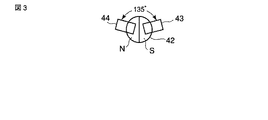
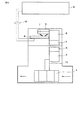
以下、図面を参照して本発明の実施形態を説明する。図1は、その一実施形態を示す概略構成図であり、水道水の流れる水通路内に回転自在に配設され、該水流に比例して回転する羽根車41と、羽根車41の該羽根車41の回転方向と直交する位置で具体的には羽根車41の回転軸411の上端部に取付けられ、図3に示すように上面から見てN極及びS極が接合されるように回転永久磁石42が形成されている。また、水通路の外壁面であって、回転永久磁石42に近接して配置され、回転永久磁石42の回転に応じて電磁誘導パルスを出力すると共に、図3に示すように互いが一定の角度例えば135度存して同一平面に配設された第1及び第2の磁気センサ43、44と、磁気センサ43からの電磁誘導パルスを出力する回転検出部451と、磁気センサ44の電磁誘導パルスの出力状態によって羽根車41の回転の正逆を判定する正逆判定部452と、正逆判定部452の出力する正逆信号及び回転検出部451からの計量パルスを受けて回転検出部451からの電磁誘導パルスを順次積算する積算計算部453を備えている。さらに、水の使用量を検針する際に使用する前述の検針盤47に組み合わせたとき、積算計算部453の積算値を、1桁づつ10進数の電気出力に変換したアナログ出力を得るアナログ出力部46とを備えている。
Hereinafter, embodiments of the present invention will be described with reference to the drawings. FIG. 1 is a schematic configuration diagram showing an embodiment of the present invention. An
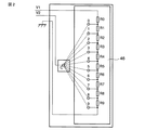
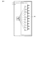
図2は、アナログ出力部46の構成を説明するための図であり、使用量の計量値を各桁ごとに数値(0〜9)をそれぞれ抵抗値により出力するもので、10個の抵抗R0〜R9を直列接続し、これら抵抗R0〜R9の各接続点0〜9とコモン接点cとを接続して使用量計量値に応じた抵抗値を出力するものとなっている。
FIG. 2 is a diagram for explaining the configuration of the
なお、図1に示す水道メータ1では1桁分の構成となっているが、実際には3〜4桁分の抵抗が備えられていたり、また各桁ごとに定電流値等を異ならせる等の切換方式が備えられた構成となっている。従って、いずれの桁においても使用量に応じた抵抗値を得、この抵抗に定電流を供給して検針電圧に変換するものとなっている。
In addition, although the
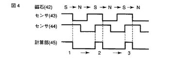
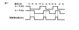
ここで、図4〜図7を参照して本実施形態の作用効果を説明する。水道水が水道水通路内に流れると、これに応じて羽根車1が回転し、羽根車1と同時に、羽根車1の回転軸に固定された回転永久磁石42が回転し、回転永久磁石42の回転磁界を磁気センサ43、44が検出し、図4に示すように磁気センサ43、44からそれぞれ位相の異なる電磁誘導パルスを発生し、これを回転検出部451及び正逆判定部452を介して積算計算部45に送出(出力)する。
Here, the effect of this embodiment is demonstrated with reference to FIGS. When the tap water flows into the tap water passage, the
ここで、正逆判定部452は、磁気センサ43、44で発生するパルス波形の状態から水道水の流れ方向が正しい場合は、例えば図5のようになり、また逆方向の場合には図6のようになること、水道メータの据付が正しいかどうかが明らかである。
Here, when the flow direction of tap water is correct from the state of the pulse waveform generated by the
一方、回転検出部451は、図7に示すように回転永久磁石42の回転開始時は、センサ43の立下りとなった時計量パルスを作成し始め、センサ44の立下りとなった時計量パルスの作成終了し、センサ44が立上がりとなった状態で計量パルスを作成し始め、センサ43の立下りとなった時計量パルスの作成を終了し、以下同様におこなう。
On the other hand, as shown in FIG. 7, the
積算計算部453では、正逆判定部452で正逆の判定結果に基づき、回転検出部451からの計量パルスを前回値にプラスかマイナスする。具体的には、正逆判定部452で正と判定した時にはプラスし、また逆と判定した時にはマイナスする。
以上述べた実施形態によれば、羽根車41の回転を、羽根車41に取付けた回転永久磁石42と、磁気センサ43、44により検出し、この検出値を積算するようにしたので、アナログ出力部46を持つ水道メータの小流量域で器差を小さくすることができ、近い将来実施される新しい計量法にも対応可能となる。また、積算計算部453の出力側にアナログ出力部46が設けられているので、従来のアナログ出力部(アナログ出力機能部)を持つ水道メータが需要家に設置されている既設の検針盤47を交換することなく水道メータのみの置き換えで設置することができる。
The
According to the embodiment described above, the rotation of the
(変形例)
前述の実施形態では、水計量パルスを積算する積算計算部453内の値を、検針盤47が読み出す際に使用するアナログ出力部46として、図2に示す電圧出力に変換する方式のものを例に挙げたが、これを図8に示すように電流出力に変換する方式であっても同様に実施できる。
(Modification)
In the above-described embodiment, the
前述の実施形態では、水道メータに正逆判定部452を備えたものを例に挙げて説明したが、用途、使用状態等によって水道水の流れの方向が一定の場合には、正逆判定部452を設けない場合であっても、前述の実施形態と同様な作用効果が得られる。
In the above-described embodiment, the example in which the water meter includes the forward /
1…羽根車、2…下部ギア列、3…駆動用永久磁石、4…受動用永久磁石、5…上部ギア列、6…回転レジスタ、7…接点、8…基板、9…使用量検針装置(検針盤)、10…ケーブル、41…羽根車、42…回転永久磁石、43…磁気センサ、44…磁気センサ、45…積算計算部、46…アナログ出力部、47…検針盤、411…回転軸、451…回転検出部、452…正逆判定部、453…積算計算部。
DESCRIPTION OF
Claims (4)
前記羽根車の該羽根車の回転方向と直交する位置に取付けられ、N極及びS極
を備えた回転永久磁石と、
前記水通路の外壁面であって、前記回転永久磁石に近接して配置され、前記回転永久磁石の回転に応じて電磁誘導パルスを出力する磁気センサと、
前記磁気センサからの電磁誘導パルスを出力する回転検出部と、
前記回転検出部からの電磁誘導パルスを順次積算する積算計算部と、
前記水の使用量を検針する際に使用する検針盤に組み合わせたとき、前記積算計算部の積算値を、1桁づつ10進数の電気出力に変換したアナログ出力を得るアナログ出力部と、
を備えた水道メータ。 An impeller disposed in a water passage through which tap water flows, and rotating in proportion to the water flow;
A rotating permanent magnet mounted at a position perpendicular to the rotational direction of the impeller of the impeller and having an N pole and an S pole;
A magnetic sensor that is an outer wall surface of the water passage and is disposed in proximity to the rotating permanent magnet, and outputs an electromagnetic induction pulse according to the rotation of the rotating permanent magnet;
A rotation detector that outputs an electromagnetic induction pulse from the magnetic sensor;
An integration calculation unit for sequentially integrating electromagnetic induction pulses from the rotation detection unit;
An analog output unit for obtaining an analog output obtained by converting the integrated value of the integrated calculation unit into a decimal electrical output by one digit when combined with a meter reading board used for metering the amount of water used;
Water meter equipped with.
前記積算計算部は、前記正逆判定部の出力する正逆信号及び前記回転検出部からの計量パルスを受けて積算計算するようにした請求項1記載の水道メータ。 Add a forward / reverse determination unit for determining forward / reverse rotation of the impeller according to the output state of the electromagnetic induction pulse of the magnetic sensor unit,
The water meter according to claim 1, wherein the integration calculation unit receives and calculates the normal / reverse signal output from the normal / reverse determination unit and the measurement pulse from the rotation detection unit.
Priority Applications (1)
| Application Number | Priority Date | Filing Date | Title |
|---|---|---|---|
| JP2005054229A JP2006242573A (en) | 2005-02-28 | 2005-02-28 | Water meter |
Applications Claiming Priority (1)
| Application Number | Priority Date | Filing Date | Title |
|---|---|---|---|
| JP2005054229A JP2006242573A (en) | 2005-02-28 | 2005-02-28 | Water meter |
Publications (1)
| Publication Number | Publication Date |
|---|---|
| JP2006242573A true JP2006242573A (en) | 2006-09-14 |
Family
ID=37049154
Family Applications (1)
| Application Number | Title | Priority Date | Filing Date |
|---|---|---|---|
| JP2005054229A Pending JP2006242573A (en) | 2005-02-28 | 2005-02-28 | Water meter |
Country Status (1)
| Country | Link |
|---|---|
| JP (1) | JP2006242573A (en) |
Citations (5)
| Publication number | Priority date | Publication date | Assignee | Title |
|---|---|---|---|---|
| JPS49111655A (en) * | 1973-02-22 | 1974-10-24 | ||
| JPS5393147U (en) * | 1976-12-25 | 1978-07-29 | ||
| JPH01296114A (en) * | 1988-05-25 | 1989-11-29 | Toshiba Corp | water meter |
| JPH0514839U (en) * | 1991-08-05 | 1993-02-26 | 日本電気株式会社 | Electronic flow meter |
| JP2001221665A (en) * | 2000-02-08 | 2001-08-17 | Toshiba Meter Techno Kk | Flowmeter |
-
2005
- 2005-02-28 JP JP2005054229A patent/JP2006242573A/en active Pending
Patent Citations (5)
| Publication number | Priority date | Publication date | Assignee | Title |
|---|---|---|---|---|
| JPS49111655A (en) * | 1973-02-22 | 1974-10-24 | ||
| JPS5393147U (en) * | 1976-12-25 | 1978-07-29 | ||
| JPH01296114A (en) * | 1988-05-25 | 1989-11-29 | Toshiba Corp | water meter |
| JPH0514839U (en) * | 1991-08-05 | 1993-02-26 | 日本電気株式会社 | Electronic flow meter |
| JP2001221665A (en) * | 2000-02-08 | 2001-08-17 | Toshiba Meter Techno Kk | Flowmeter |
Similar Documents
| Publication | Publication Date | Title |
|---|---|---|
| US6956366B2 (en) | Arrangement for determining the position of a motion sensor element influencing the formation of a magnetic field of a working magnet along its motion coordinate | |
| US9316482B2 (en) | Magnetic multi-turn absolute position detection device | |
| US5941122A (en) | Liquid level sensor incorporating a capacitive rotary position encoder | |
| CN102589412B (en) | Angular transducer | |
| JP5144528B2 (en) | Rotation angle detector | |
| CN104062609A (en) | Detection Circuit, Semiconductor Integrated Circuit Device, Magnetic Field Rotation Angle Detection Device, And Electronic Device | |
| JP2006126012A (en) | Magneto-electric conversion system, magneto-electric conversion apparatus and its control circuit | |
| CN106441466B (en) | Magneto-electric water meter | |
| JP4488344B2 (en) | Water meter | |
| JP2005308740A (en) | Magneto-dielectric flow measurement method and magneto-dielectric flow meter | |
| US7994772B2 (en) | Remote transmitter for analogue gauges | |
| JP2006242573A (en) | Water meter | |
| JP4199149B2 (en) | Liquid level measurement system | |
| JP3325053B2 (en) | Electronic vertical plumbing water meter | |
| CN213363900U (en) | Flow nonmagnetic metering device | |
| US20050052179A1 (en) | Method and device for preparing a sensor signal of a position sensor for transmission to an evaluation unit | |
| JPH06273202A (en) | Flow rate measuring device | |
| JP2011163924A (en) | Liquid level measuring system | |
| KR100872117B1 (en) | Rotation control device to reduce the noise of the motor. | |
| EP0062531B1 (en) | Electromagnetic flow meter | |
| KR100835438B1 (en) | Magnetic detector | |
| JP2006250780A (en) | Fluid usage meter and fluid usage measurement method | |
| JP3600064B2 (en) | Flow meter and flow control device | |
| JP4828090B2 (en) | Relative rotational position detector | |
| US6508116B1 (en) | Water bike equipped with speed meter |
Legal Events
| Date | Code | Title | Description |
|---|---|---|---|
| A621 | Written request for application examination |
Free format text: JAPANESE INTERMEDIATE CODE: A621 Effective date: 20071212 |
|
| A711 | Notification of change in applicant |
Effective date: 20100301 Free format text: JAPANESE INTERMEDIATE CODE: A712 |
|
| A977 | Report on retrieval |
Free format text: JAPANESE INTERMEDIATE CODE: A971007 Effective date: 20101018 |
|
| A131 | Notification of reasons for refusal |
Effective date: 20101026 Free format text: JAPANESE INTERMEDIATE CODE: A131 |
|
| A02 | Decision of refusal |
Free format text: JAPANESE INTERMEDIATE CODE: A02 Effective date: 20110301 |