JP2006242596A - Organic halide detection device in oil - Google Patents
Organic halide detection device in oil Download PDFInfo
- Publication number
- JP2006242596A JP2006242596A JP2005054914A JP2005054914A JP2006242596A JP 2006242596 A JP2006242596 A JP 2006242596A JP 2005054914 A JP2005054914 A JP 2005054914A JP 2005054914 A JP2005054914 A JP 2005054914A JP 2006242596 A JP2006242596 A JP 2006242596A
- Authority
- JP
- Japan
- Prior art keywords
- oil
- organic halide
- chamber
- unit
- ultraviolet light
- Prior art date
- Legal status (The legal status is an assumption and is not a legal conclusion. Google has not performed a legal analysis and makes no representation as to the accuracy of the status listed.)
- Withdrawn
Links
- 150000004820 halides Chemical class 0.000 title claims abstract description 65
- 238000001514 detection method Methods 0.000 title claims abstract description 42
- 230000001678 irradiating effect Effects 0.000 claims abstract description 6
- 238000005259 measurement Methods 0.000 claims description 14
- 229910052801 chlorine Inorganic materials 0.000 abstract description 10
- 125000001309 chloro group Chemical group Cl* 0.000 abstract description 4
- 230000005670 electromagnetic radiation Effects 0.000 abstract description 3
- -1 PCB Chemical class 0.000 abstract description 2
- 238000010494 dissociation reaction Methods 0.000 abstract description 2
- 230000005593 dissociations Effects 0.000 abstract description 2
- 238000004458 analytical method Methods 0.000 description 12
- 239000000460 chlorine Substances 0.000 description 9
- 238000010586 diagram Methods 0.000 description 9
- 235000017168 chlorine Nutrition 0.000 description 8
- ZAMOUSCENKQFHK-UHFFFAOYSA-N Chlorine atom Chemical compound [Cl] ZAMOUSCENKQFHK-UHFFFAOYSA-N 0.000 description 6
- 230000007423 decrease Effects 0.000 description 5
- 150000004045 organic chlorine compounds Chemical class 0.000 description 5
- 230000005540 biological transmission Effects 0.000 description 4
- 238000012545 processing Methods 0.000 description 4
- 238000000034 method Methods 0.000 description 3
- 150000003071 polychlorinated biphenyls Chemical group 0.000 description 3
- 101000694017 Homo sapiens Sodium channel protein type 5 subunit alpha Proteins 0.000 description 2
- PXHVJJICTQNCMI-UHFFFAOYSA-N Nickel Chemical compound [Ni] PXHVJJICTQNCMI-UHFFFAOYSA-N 0.000 description 2
- 125000004429 atom Chemical group 0.000 description 2
- 239000000470 constituent Substances 0.000 description 2
- 238000000354 decomposition reaction Methods 0.000 description 2
- 238000009792 diffusion process Methods 0.000 description 2
- 230000005281 excited state Effects 0.000 description 2
- PCHJSUWPFVWCPO-UHFFFAOYSA-N gold Chemical compound [Au] PCHJSUWPFVWCPO-UHFFFAOYSA-N 0.000 description 2
- 229910052737 gold Inorganic materials 0.000 description 2
- 239000010931 gold Substances 0.000 description 2
- 238000009434 installation Methods 0.000 description 2
- 238000004255 ion exchange chromatography Methods 0.000 description 2
- 238000001228 spectrum Methods 0.000 description 2
- RYGMFSIKBFXOCR-UHFFFAOYSA-N Copper Chemical compound [Cu] RYGMFSIKBFXOCR-UHFFFAOYSA-N 0.000 description 1
- NINIDFKCEFEMDL-UHFFFAOYSA-N Sulfur Chemical compound [S] NINIDFKCEFEMDL-UHFFFAOYSA-N 0.000 description 1
- 238000002485 combustion reaction Methods 0.000 description 1
- 238000011109 contamination Methods 0.000 description 1
- 229910052802 copper Inorganic materials 0.000 description 1
- 239000010949 copper Substances 0.000 description 1
- 238000005260 corrosion Methods 0.000 description 1
- 230000007797 corrosion Effects 0.000 description 1
- 238000011161 development Methods 0.000 description 1
- 230000005283 ground state Effects 0.000 description 1
- 229910052736 halogen Inorganic materials 0.000 description 1
- 150000002367 halogens Chemical class 0.000 description 1
- 238000002347 injection Methods 0.000 description 1
- 239000007924 injection Substances 0.000 description 1
- 239000000463 material Substances 0.000 description 1
- 238000004452 microanalysis Methods 0.000 description 1
- 239000000203 mixture Substances 0.000 description 1
- 238000012544 monitoring process Methods 0.000 description 1
- 229910052759 nickel Inorganic materials 0.000 description 1
- 230000003287 optical effect Effects 0.000 description 1
- 238000011160 research Methods 0.000 description 1
- 239000000126 substance Substances 0.000 description 1
- 229910052717 sulfur Inorganic materials 0.000 description 1
- 239000011593 sulfur Substances 0.000 description 1
- 238000002834 transmittance Methods 0.000 description 1
- 238000011144 upstream manufacturing Methods 0.000 description 1
- 238000009834 vaporization Methods 0.000 description 1
- 230000008016 vaporization Effects 0.000 description 1
- 239000002699 waste material Substances 0.000 description 1
Images

Landscapes
- Investigating, Analyzing Materials By Fluorescence Or Luminescence (AREA)
Abstract
Description
本発明は、油中の有機ハロゲン化物検出装置に関する。 The present invention relates to a device for detecting an organic halide in oil.
従来絶縁油として使用されたトランス等はPCB汚染容器とされ、そのPCB汚染容器は確実に処理しなければならないことが義務化された(ポリ塩化ビフェニル廃棄物の適正な処理の推進に関する特別措置法「PCB特別措置法」、平成13年6月22日法律第65号)。
また、PCBを処理するPCB処理プラント運転のためには、PCB汚染容器の受け入れを迅速に行うことが急務である。
このため、PCB汚染容器がどの程度汚染されているかのPCBの塩素濃度の迅速な把握が必要である。これは、PCB処理施設のPCB油の分解処理運転のための薬剤の投入条件の決定に寄与するからである。
そこで、処理PCB油中の塩素濃度の迅速な分析やモニタリングをすることが切望されている。
Conventionally, transformers used as insulating oil are considered to be PCB contaminated containers, and the PCB contaminated containers must be treated reliably (Special Measures Law for Promotion of Proper Treatment of Polychlorinated Biphenyl Waste) “PCB Special Measures Law”, Law No. 65, June 22, 2001).
In addition, in order to operate a PCB processing plant for processing PCBs, it is urgent to quickly accept PCB contaminated containers.
For this reason, it is necessary to quickly know the chlorine concentration of the PCB to what extent the PCB contaminated container is contaminated. This is because it contributes to the determination of the chemical injection conditions for the PCB oil decomposition processing operation of the PCB processing facility.
Thus, there is an urgent need for rapid analysis and monitoring of the chlorine concentration in the treated PCB oil.
従来においては、PCBの公定分析がJISに定められている(非特許文献1)。また、燃焼分解法とイオンクロマトグラフ法とを組合せた分析方法が提案されている(非特許文献2)。 Conventionally, official analysis of PCB is defined in JIS (Non-patent Document 1). An analysis method combining a combustion decomposition method and an ion chromatography method has been proposed (Non-Patent Document 2).
しかしながら従来の公定分析では、その分析に3〜5日と長時間を要するという問題がある。また、人間による分析手法であるので、全自動化が不可能である。
また、分析には試料を多量に使用(数mgオーダ)することが求められており、油中塩素に暴露する可能性があり、安全性を厳重にする必要がある。
よって、分析に時間を要せず、安全性が確保された分析手法の出現が切望されている。
However, the conventional official analysis has a problem that the analysis takes 3 to 5 days. Moreover, since it is a human analysis technique, it cannot be fully automated.
In addition, the analysis requires the use of a large amount of sample (on the order of several mg), and there is a possibility of exposure to chlorine in oil, so safety must be tightened.
Therefore, the emergence of analysis methods that do not require time and ensure safety is eagerly desired.
本発明は、前記問題に鑑み、PCB等の有機ハロゲン化物が油中に存在する場合にその濃度を迅速に分析することができる油中の有機ハロゲン化物検出装置を提供することを課題とする。 This invention makes it a subject to provide the organic halide detection apparatus in oil which can analyze the density | concentration rapidly, when organic halides, such as PCB, exist in oil in view of the said problem.
上述した課題を解決するための本発明の第1の発明は、有機ハロゲン化物を含有する油をチャンバ内に供給する油供給部と、チャンバ内の油に紫外光を照射する紫外光照射部と、紫外光の照射により発生した蛍光を検出する光検出部とを具備することを特徴とする油中の有機ハロゲン化物検出装置にある。 The first invention of the present invention for solving the above-described problems includes an oil supply unit that supplies oil containing an organic halide into the chamber, an ultraviolet light irradiation unit that irradiates the oil in the chamber with ultraviolet light, and And an organic halide detecting device in oil, comprising: a light detecting portion for detecting fluorescence generated by irradiation with ultraviolet light.
第2の発明は、第1の発明において、前記光検出部が紫外線の照射光路と同軸又は直交する軸に設置されていることを特徴とする油中の有機ハロゲン化物検出装置にある。 According to a second invention, there is provided the organic halide detection apparatus in oil according to the first invention, wherein the light detection unit is installed on an axis that is coaxial or orthogonal to an ultraviolet irradiation light path.
第3の発明は、第1の発明において、前記紫外線照射部がパルスレーザ光源であると共に、光検出部が時間分解測定部を有することを特徴とする油中の有機ハロゲン化物検出装置にある。 According to a third invention, there is provided the organic halide detection apparatus in oil according to the first invention, wherein the ultraviolet irradiation unit is a pulse laser light source and the light detection unit has a time-resolved measurement unit.
第4の発明は、第3の発明において、チャンバ内を1000Pa以下の真空状態とする真空排気部を有することを特徴とする油中の有機ハロゲン化物検出装置にある。 According to a fourth aspect of the present invention, there is provided the organic halide detection apparatus in oil according to the third aspect of the present invention, further comprising a vacuum exhaust unit that evacuates the chamber to a vacuum state of 1000 Pa or less.
第5の発明は、第4の発明において、前記油供給部が微量油供給部であると共に、チャンバにスキマーを配設し、有機ハロゲン化物を含む油を断熱膨張拡散させる第1の真空排気部を有する第1の部屋と、レーザ光を照射して電子励起させて蛍光を発生させる第2の真空排気部を有する第2の部屋とを有する油中の有機ハロゲン化物検出装置にある。 A fifth invention is the first vacuum exhaust part according to the fourth invention, wherein the oil supply part is a trace oil supply part, and a skimmer is provided in the chamber to adiabatic expansion and diffusion of oil containing an organic halide. And an organic halide detecting device in oil having a second chamber having a second evacuation unit for generating fluorescence by irradiating a laser beam to generate electrons.
本発明によれば、有機ハロゲン化物である例えばPCBを簡易迅速に計測することができる。 According to the present invention, an organic halide such as PCB can be measured easily and quickly.
以下、この発明につき図面を参照しつつ詳細に説明する。なお、この実施例によりこの発明が限定されるものではない。また、下記実施例における構成要素には、当業者が容易に想定できるもの、あるいは実質的に同一のものが含まれる。 Hereinafter, the present invention will be described in detail with reference to the drawings. Note that the present invention is not limited to the embodiments. In addition, constituent elements in the following embodiments include those that can be easily assumed by those skilled in the art or those that are substantially the same.
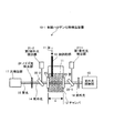
本発明による実施例1に係る油中の有機ハロゲン化物検出装置について、図面を参照して説明する。図1は、実施例1に係る油中の有機ハロゲン化物検出装置を示す概念図である。図1に示すように、本実施例に係る油中の有機ハロゲン化物検出装置10−1は、有機ハロゲン化物を含有する油11をチャンバ12内に供給する油供給部13と、チャンバ12内の油11に紫外光14を照射する紫外光照射部15と、前記紫外光14の照射により油分子中の塩素原子解離に伴う電磁輻射である蛍光16を発生させ、発生した蛍光16を検出する光検出部17とを具備するものである。
図1中、符号21−1は第1紫外線検出器、21−2は第2紫外線検出器、22−1、22−2は反射レンズ、23はチャンバの窓、24はノイズ光除去部を各々図示する。
An apparatus for detecting an organic halide in oil according to Example 1 of the present invention will be described with reference to the drawings. FIG. 1 is a conceptual diagram showing a device for detecting an organic halide in oil according to the first embodiment. As shown in FIG. 1, an organic halide detection apparatus 10-1 in oil according to the present embodiment includes an oil supply unit 13 that supplies
In FIG. 1, reference numeral 21-1 is a first ultraviolet detector, 21-2 is a second ultraviolet detector, 22-1 and 22-2 are reflection lenses, 23 is a chamber window, and 24 is a noise light removing unit. Illustrated.
油11中に紫外光14を照射させ、有機塩素化合物由来の蛍光波長・強度を光検出部17で検出することによって、有機塩素化合物濃度を定量し、塩素濃度を算出することができる。
By irradiating the
前記紫外線照射部15は、油11に紫外光14を照射し、油分子中の電磁輻射である蛍光を発生させるためのものである。その波長としては、100〜500nm、好適には200〜400nmとするのがよい。
また、その出力としては、0.005〜100W/cm2、好適には0.1〜10W/cm2とするのがよい。
また、紫外線の照射により発生する蛍光波長は200〜500nmである。
発生した蛍光16はチャンバ12の窓23から紫外光14と共に外部に透過する。そして、この紫外光14と蛍光16とが混合されたものから蛍光のみを分離するために、例えばフィルタ等のノイズ光除去部24が設けられている。
The
As the output, 0.005~100W / cm 2, preferably preferably set to 0.1 to 10 / cm 2.
Moreover, the fluorescence wavelength generated by irradiation with ultraviolet rays is 200 to 500 nm.
The generated fluorescence 16 passes through the
また、光検出部17としては、例えばフォトダイオード、光電子増倍管、ICCDカメラ等を挙げることができるが、本発明はこれに限定されるものではない。 Examples of the light detection unit 17 include a photodiode, a photomultiplier tube, and an ICCD camera, but the present invention is not limited to this.
また、蛍光を検出する光検出部17は、ICCDカメラ、光電子増倍管等を挙げることができる。 Examples of the light detection unit 17 that detects fluorescence include an ICCD camera and a photomultiplier tube.
また、第1紫外光検出器21−1の測定値をI0とし、第2紫外光検出器21−2の測定値をI1とする。各測定値よりI1/I0を測定する。その後、下式(1)に当てはめて、濃度を定量する
I1=I0×10-εcl・・・(1)
ここで、式(1)において、εは定数、cは濃度、lはチャンバ12の長さである。
Also, the measured value of the first ultraviolet light detector 21-1 is I 0, and the measured value of the second ultraviolet light detector 21-2 is I 1 . I 1 / I 0 is measured from each measured value. Then, by applying the following
Here, in Expression (1), ε is a constant, c is a concentration, and l is the length of the chamber 12.
なお、紫外光照射部15からの紫外光14の光強度が既知であり、測定中変動することがないとすれば、第1紫外光検出器21−1を設置する必要はない。
In addition, if the light intensity of the ultraviolet light 14 from the ultraviolet
本実施形態に係る油中の有機ハロゲン化物検出装置によれば、その分析に要する時間は約10分程度となり、分析時間の大幅な短縮が可能となる。また、公定法による煩雑な手作業による分析操作を必要とせず、安全性が確保される。 According to the organic halide detection apparatus in oil according to the present embodiment, the time required for the analysis is about 10 minutes, and the analysis time can be greatly shortened. In addition, it does not require a complicated manual analysis operation by an official method, and safety is ensured.
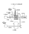
本発明による実施例2に係る油中の有機ハロゲン化物検出装置について、図面を参照して説明する。図2は、実施例2に係る油中の有機ハロゲン化物検出装置を示す概念図である。なお、実施例1に係る油中の有機ハロゲン化物検出装置と同一の構成部材については、同一の符号を付してその説明は省略する。図2に示すように、本実施例に係る油中の有機ハロゲン化物検出装置10−2は、第1紫外線検出部での検出精度を向上させるために、第1紫外光検出器21−1の設置をチャンバ12の前後とはせず、別光路としたものである。すなわち、空容器25を設置して、反射した紫外光14を反射部22−2で反射させ、空容器25を通過した後の紫外光14を検出するようにしている。同じ形状及び材質のチャンバ容器を通すことで、油による吸収光のみを検出する精度が向上する。 An apparatus for detecting an organic halide in oil according to Embodiment 2 of the present invention will be described with reference to the drawings. FIG. 2 is a conceptual diagram illustrating a device for detecting an organic halide in oil according to the second embodiment. In addition, about the same component as the organic halide detection apparatus in oil which concerns on Example 1, the same code | symbol is attached | subjected and the description is abbreviate | omitted. As shown in FIG. 2, the organic halide detection apparatus 10-2 in oil according to the present embodiment includes the first ultraviolet light detector 21-1 in order to improve the detection accuracy in the first ultraviolet light detector. The installation is not performed before and after the chamber 12 but is a separate optical path. That is, the empty container 25 is installed, the reflected ultraviolet light 14 is reflected by the reflection part 22-2, and the ultraviolet light 14 after passing through the empty container 25 is detected. By passing the chamber container of the same shape and material, the accuracy of detecting only the light absorbed by the oil is improved.
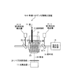
本発明による実施例3に係る油中の有機ハロゲン化物検出装置について、図面を参照して説明する。図3は、実施例3に係る油中の有機ハロゲン化物検出装置を示す概念図である。なお、実施例1に係る油中の有機ハロゲン化物検出装置と同一の構成部材については、同一の符号を付してその説明は省略する。図3に示すように、本実施例に係る油中の有機ハロゲン化物検出装置10−3は、光検出部17の設置位置を紫外光14の軸と直交する軸となるようにしている。
これにより、実施例1の油中の有機ハロゲン化物検出装置10−1に比べて紫外光照射部15に起因する迷光除去が可能となる。また、高感度な計測が達成される。
An apparatus for detecting an organic halide in oil according to Example 3 according to the present invention will be described with reference to the drawings. FIG. 3 is a conceptual diagram illustrating a device for detecting an organic halide in oil according to a third embodiment. In addition, about the same component as the organic halide detection apparatus in oil which concerns on Example 1, the same code | symbol is attached | subjected and the description is abbreviate | omitted. As shown in FIG. 3, the organic halide detection apparatus 10-3 in oil according to the present embodiment is configured such that the installation position of the light detection unit 17 is an axis orthogonal to the axis of the ultraviolet light 14.
Thereby, compared with the organic halide detection apparatus 10-1 in oil of Example 1, the stray light resulting from the ultraviolet
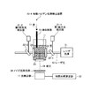
本発明による実施例4に係る油中の有機ハロゲン化物検出装置について、図面を参照して説明する。図4は、実施例4に係る油中の有機ハロゲン化物検出装置を示す概念図である。なお、実施例1〜3に係る油中の有機ハロゲン化物検出装置と同一の構成部材については、同一の符号を付してその説明は省略する。図4に示すように、本実施例に係る油中の有機ハロゲン化物検出装置10−4は、実施例1及び2の紫外光照射部15の代わりに、レーザ光源31を設置している。また、時間分解測定部32を光検出部17に設けている。
また、レーザ光源31はパルスレーザであり、発振されたレーザ光33を油に照射し、蛍光を発生させる。併せて蛍光強度の時間変化を測定することによって、有機塩素化合物濃度定量を行うことができる。
An apparatus for detecting an organic halide in oil according to Example 4 of the present invention will be described with reference to the drawings. FIG. 4 is a conceptual diagram illustrating a device for detecting an organic halide in oil according to a fourth embodiment. In addition, about the same structural member as the organic halide detection apparatus in oil which concerns on Examples 1-3, the same code | symbol is attached | subjected and the description is abbreviate | omitted. As shown in FIG. 4, the organic halide detection apparatus 10-4 in oil according to the present embodiment is provided with a
The
前記時間分解測定部32は、その時間分解能が0.01〜10psec、好適には0.1〜1psecである。なお、1.0psec=1.0×10⁻¹² secである。
例えば測定部の装置として例えばオシロスコープ、ボックスカー積算器、フォトンカウンタ等を挙げることができる。
また、レーザ光源31は、油中分子にレーザを照射し、電子励起させ蛍光を発生させる例えばパルスレーザ光源を用いる。
ここで、レーザ波長としては、例えば100〜400nm、好適には220〜250nmである。
また、その出力としては、0.05〜10W/cm2、好適には0.1〜1W/cm2とするのがよい。
レーザパルス時間幅は0.01〜1000nsec、好適には1〜10nsecである。1.0nsec=1.0×10⁻⁹secである。
The time resolution measurement unit 32 has a time resolution of 0.01 to 10 psec, preferably 0.1 to 1 psec. Note that 1.0 psec = 1.0 × 10 −12 sec.
For example, as an apparatus of the measurement unit, for example, an oscilloscope, a boxcar integrator, a photon counter, and the like can be given.
In addition, the
Here, the laser wavelength is, for example, 100 to 400 nm, preferably 220 to 250 nm.
The output is 0.05 to 10 W / cm 2 , preferably 0.1 to 1 W / cm 2 .
The laser pulse time width is 0.01 to 1000 nsec, preferably 1 to 10 nsec. 1.0 nsec = 1.0 × 10 −9 sec.
ここで、蛍光強度の時間変化計測について説明する。
光励起状態(A*状態)の分子(有機ハロゲン化物)数をN(A*)とし、基底状態の分子(有機ハロゲン化物)数をN(A)とすると、式(2)となる。
Here, the time change measurement of the fluorescence intensity will be described.
When the number of molecules (organic halide) in the photoexcited state (A * state) is N (A *) and the number of molecules in the ground state (organic halide) is N (A), the equation (2) is obtained.
N(A*)=N(A)exp(−Bτ)・・・(2)
ここで、Bは定数である。τは光励起状態(A*状態)における分子(有機ハロゲン化物)の寿命である。前記式(2)中、Bは各分子(有機ハロゲン化物)につき固有である。よって得られた時間変化データから、各分子(有機ハロゲン化物)につきN(A)を算出することが可能となる。
N (A *) = N (A) exp (−Bτ) (2)
Here, B is a constant. τ is the lifetime of the molecule (organic halide) in the photoexcited state (A * state). In the formula (2), B is unique to each molecule (organic halide). Therefore, N (A) can be calculated for each molecule (organic halide) from the obtained time change data.
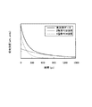
例えば、PCBの場合、置換塩素数の少ないPCB(2塩素PCBなど)は、上式中Bの絶対値が小さいため寿命が長く(励起状態に留まる時間が長い)、置換塩素数の多いPCB(5塩素PCBなど)は、上式中Bの絶対値が大きいため、寿命が短い。すなわち、励起状態に留まる時間が短い。
このことから図5に示す太線の実計測データにより得られた蛍光強度時間変化スペクトルを、2塩素PCB強度と5塩素PCB強度のようにフィッティングすることができる。このフィッティング結果から、塩素置換PCB濃度を定量することができる。また、塩素濃度も併せて算出することができる。
For example, in the case of PCB, a PCB with a small number of substituted chlorines (such as a 2-chlorine PCB) has a long life (long time for staying in an excited state) because the absolute value of B in the above formula is small, and a PCB with a large number of substituted chlorines ( 5 chlorine PCB) has a short life because the absolute value of B in the above formula is large. That is, the time for staying in the excited state is short.
From this, it is possible to fit the fluorescence intensity time-varying spectrum obtained from the actual measurement data of the thick line shown in FIG. 5 like the 2-chlorine PCB intensity and the 5-chlorine PCB intensity. From this fitting result, the chlorine-substituted PCB concentration can be quantified. Further, the chlorine concentration can also be calculated.
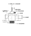
本発明による実施例5に係る油中の有機ハロゲン化物検出装置について、図面を参照して説明する。図6は、実施例5に係る油中の有機ハロゲン化物検出装置を示す概念図である。なお、実施例1〜3に係る油中の有機ハロゲン化物検出装置と同一の構成部材については、同一の符号を付してその説明は省略する。図6に示すように、本実施例に係る油中の有機ハロゲン化物検出装置10−5は、チャンバ12の内を1000Pa以下の真空状態とする真空排気部45を有するものである。なお、図6においては、図1の有機ハロゲン化物検出装置10−1と同一の構成部材のものは一部省略し、チャンバ12部分を示している。なお、図中符号11aは油が気化して発生したガス、符号46は光検出用窓を図示する。 An apparatus for detecting an organic halide in oil according to Example 5 of the present invention will be described with reference to the drawings. FIG. 6 is a conceptual diagram illustrating a device for detecting an organic halide in oil according to the fifth embodiment. In addition, about the same structural member as the organic halide detection apparatus in oil which concerns on Examples 1-3, the same code | symbol is attached | subjected and the description is abbreviate | omitted. As shown in FIG. 6, the organic halide detection apparatus 10-5 in oil according to the present embodiment includes a vacuum exhaust unit 45 that evacuates the chamber 12 to 1000 Pa or less. In FIG. 6, the same constituent members as those of the organic halide detector 10-1 in FIG. 1 are partially omitted, and the chamber 12 portion is shown. In the figure, reference numeral 11a denotes a gas generated by vaporization of oil, and reference numeral 46 denotes a light detection window.
ここで、レーザ光のもつエネルギーにより油滴内分子が電子励起される。その際、励起した有機塩素化合物が他分子・原子と衝突してしまうことがある。この場合、励起した有機塩素化合物がもつエネルギーが失われ(失活)てしまう。このような場合、蛍光強度低下もしくは計測精度の低下がおこる。このような問題を解決するため、チャンバ12内を真空に保持するようにしている。 Here, the molecules in the oil droplets are electronically excited by the energy of the laser beam. At that time, the excited organochlorine compound may collide with other molecules and atoms. In this case, the energy of the excited organic chlorine compound is lost (deactivated). In such a case, the fluorescence intensity decreases or the measurement accuracy decreases. In order to solve such a problem, the inside of the chamber 12 is kept in a vacuum.
真空に保持した場合、周囲雰囲気ガス密度が低下するため、衝突頻度(確率)が低下する。このため、衝突による光強度低下はなく、計測精度も確保できる。ここで、真空度としては1000Pa以下の真空状態としている。
平均自由行程λ(分子が衝突するまでに進む平均長さ)は圧力pに対して次式(3)のような関係がある。
λ∝1/p・・・(3)
ガス組成及び温度が同じ場合、1000Pa以下の真空状態では、大気圧下と比べておよそ100倍平均自由行程は長くなり、その結果衝突頻度が低減される。
When kept in a vacuum, the ambient atmosphere gas density decreases, so the collision frequency (probability) decreases. For this reason, the light intensity is not reduced by the collision, and the measurement accuracy can be secured. Here, the degree of vacuum is 1000 Pa or less.
The mean free path λ (the mean length traveled until the molecules collide) has a relationship with the pressure p as shown in the following formula (3).
λ∝1 / p (3)
When the gas composition and temperature are the same, the mean free path is about 100 times longer in a vacuum state of 1000 Pa or less than under atmospheric pressure, and as a result, the collision frequency is reduced.
本実施例では、油滴を供給する手段として微量油供給部41を設けており、例えばニードル弁、キャピラリ、キャピラリアレー、パルス開閉バルブ等を挙げることができる。
また、真空排気部45は、チャンバ12の内部真空度を1000Pa以内に保持できるものであれば、ターボポンプ、油回転ポンプ、ダイアフラムポンプ及びスクロールポンプ等を挙げることができる。
In the present embodiment, a trace oil supply unit 41 is provided as means for supplying oil droplets, and examples thereof include a needle valve, a capillary, a capillary array, and a pulse open / close valve.
The vacuum exhaust unit 45 may be a turbo pump, an oil rotary pump, a diaphragm pump, a scroll pump, or the like as long as the internal vacuum degree of the chamber 12 can be maintained within 1000 Pa.
油が気化して発生したガス11aとして容器内に供給される際、油分子に断熱膨張がおこる。油分子が拡散するため、壁・窓などに油成分が付着しやすくなる。特に油成分ガスが窓表面に付着することを防止する必要がある。油成分ガスが窓表面に付着すると、レーザ光照射によって窓表面油成分が焼けてしまい、光透過率が低下する。 When the oil is vaporized and supplied as a gas 11a into the container, adiabatic expansion occurs in the oil molecules. Since oil molecules diffuse, oil components easily adhere to walls and windows. In particular, it is necessary to prevent oil component gas from adhering to the window surface. When the oil component gas adheres to the window surface, the window surface oil component is burned by the laser beam irradiation, and the light transmittance decreases.
本実施例では、筒42に設けた第1レーザ光透過窓43−1に穴(ピンホール)を空けている。そして、穴を空けた部分にレーザ光(図示せず)が透過できるようにしている。前記穴の大きさは1〜10mmφ程度とするのが好ましい。
また、チャンバ12内の気密を保つため、第2レーザ光透過窓43−2を筒42の短部に設置している。この第2レーザ光透過窓43−2の油成分ガス付着による汚れの影響は少ない。これは第1レーザ光透過窓43−1には穴(ピンホール)しか空いていないため、油成分ガスの流入の影響を低減するようにしているからである。
In the present embodiment, a hole (pinhole) is formed in the first laser light transmission window 43-1 provided in the cylinder. A laser beam (not shown) can be transmitted through the holed portion. The size of the hole is preferably about 1 to 10 mmφ.
Further, the second laser light transmission window 43-2 is installed in the short part of the
本発明による実施例6に係る油中の有機ハロゲン化物検出装置について、図面を参照して説明する。図7は、実施例6に係る油中の有機ハロゲン化物検出装置を示す概念図である。なお、実施例1〜3に係る油中の有機ハロゲン化物検出装置と同一の構成部材については、同一の符号を付してその説明は省略する。図6に示すように、本実施例に係る油中の有機ハロゲン化物検出装置10−6は、前記油供給部が微量油供給部41であると共に、チャンバ12内にスキマー47を配設し、有機ハロゲン化物を含む油を断熱膨張拡散させる第2の真空排気部45−2を有する第1の部屋12−1と、レーザ光(図示せず)を照射して電子励起させて蛍光を発生させる第1の真空排気部45−1を有する第2の部屋12−2とを有するものである。 An apparatus for detecting an organic halide in oil according to Example 6 of the present invention will be described with reference to the drawings. FIG. 7 is a conceptual diagram showing a device for detecting an organic halide in oil according to Example 6. In addition, about the same structural member as the organic halide detection apparatus in oil which concerns on Examples 1-3, the same code | symbol is attached | subjected and the description is abbreviate | omitted. As shown in FIG. 6, in the organic halide detection apparatus 10-6 in oil according to the present embodiment, the oil supply unit is a trace oil supply unit 41, and a skimmer 47 is disposed in the chamber 12, A first chamber 12-1 having a second evacuation unit 45-2 for adiabatic expansion and diffusion of oil containing an organic halide and a laser beam (not shown) is irradiated with electrons to generate fluorescence. And a second chamber 12-2 having a first vacuum exhaust part 45-1.
前記スキマー47は、計測試料を直線状の流れを形成させるために設けたものであり、例えば金、銅、ニッケル等から形成されている。なお腐食防止の観点からは、好適には金がよい。このスキマー径は0.5〜5.0mmφとするのが好ましい。また、第2の真空排気部45−2は、前記スキマー47等を用いた場合、スキマー47より上流側の第1の部屋12−1の圧力を高くさせるため、第2真空排気部45−2を有している。
前記スキマー47によりガスは直線状の分子ビーム11bとなり、窓、壁等の汚れを防止することができる。
The skimmer 47 is provided to form a linear flow of the measurement sample, and is made of, for example, gold, copper, nickel or the like. From the viewpoint of preventing corrosion, gold is preferable. The skimmer diameter is preferably 0.5 to 5.0 mmφ. In addition, when the skimmer 47 or the like is used, the second vacuum exhaust part 45-2 increases the pressure in the first chamber 12-1 on the upstream side of the skimmer 47, so that the second vacuum exhaust part 45-2. have.
By the skimmer 47, the gas becomes a linear molecular beam 11b, and contamination of windows, walls and the like can be prevented.
本実施例によれば、分析時間の更なる短縮(1分以内)を図ることができる。また、煩雑な手作業を必要とせず、安全性が確保される。
さらに、実施例1〜5に較べて油分子中の他原子衝突に伴う光強度低下はなく、計測精度も確保できる。
According to the present embodiment, the analysis time can be further shortened (within 1 minute). Further, no complicated manual work is required, and safety is ensured.
Furthermore, compared with Examples 1-5, there is no light intensity fall accompanying other atom collision in an oil molecule, and a measurement precision is securable.
以上のように、本発明に係る有機ハロゲン化物検出装置は、有機ハロゲン化物である例えばPCBを簡易迅速に計測することに用いるのに適している。 As described above, the organic halide detection device according to the present invention is suitable for use in simple and rapid measurement of, for example, PCB which is an organic halide.
10−1〜10−6 有機ハロゲン化物検出装置
11 油
12 チャンバ
13 油供給部
14 紫外光
15 紫外光照射部
16 蛍光
17 光検出部
10-1 to 10-6 Organic
Claims (5)
チャンバ内の油に紫外光を照射する紫外光照射部と、
紫外光の照射により発生した蛍光を検出する光検出部とを具備することを特徴とする油中の有機ハロゲン化物検出装置。 An oil supply section for supplying oil containing an organic halide into the chamber;
An ultraviolet light irradiation unit for irradiating the oil in the chamber with ultraviolet light;
An organic halide detection apparatus in oil, comprising: a light detection unit that detects fluorescence generated by irradiation with ultraviolet light.
前記光検出部が紫外線の照射光路と同軸又は直交する軸に設置されていることを特徴とする油中の有機ハロゲン化物検出装置。 In claim 1,
An organic halide detection apparatus in oil, wherein the light detection unit is installed on an axis that is coaxial or orthogonal to an irradiation path of ultraviolet rays.
前記紫外線照射部がパルスレーザ光源であると共に、光検出部が時間分解測定部を有することを特徴とする油中の有機ハロゲン化物検出装置。 In claim 1,
An apparatus for detecting an organic halide in oil, wherein the ultraviolet irradiation unit is a pulse laser light source, and the light detection unit includes a time-resolved measurement unit.
チャンバ内を1000Pa以下の真空状態とする真空排気部を有することを特徴とする油中の有機ハロゲン化物検出装置。 In claim 3,
An apparatus for detecting an organic halide in oil, comprising an evacuation unit that evacuates the chamber to a vacuum state of 1000 Pa or less.
前記油供給部が微量油供給部であると共に、チャンバにスキマーを配設し、有機ハロゲン化物を含む油を断熱膨張拡散させる第1の真空排気部を有する第1の部屋と、レーザ光を照射して電子励起させて蛍光を発生させる第2の真空排気部を有する第2の部屋とを有する油中の有機ハロゲン化物検出装置。 In claim 4,
The oil supply unit is a trace oil supply unit, a skimmer is disposed in the chamber, and a first chamber having a first vacuum exhaust unit for adiabatically expanding and diffusing oil containing an organic halide is irradiated with laser light. And an organic halide detecting device in oil having a second chamber having a second vacuum evacuation unit that is excited by electrons to generate fluorescence.
Priority Applications (1)
| Application Number | Priority Date | Filing Date | Title |
|---|---|---|---|
| JP2005054914A JP2006242596A (en) | 2005-02-28 | 2005-02-28 | Organic halide detection device in oil |
Applications Claiming Priority (1)
| Application Number | Priority Date | Filing Date | Title |
|---|---|---|---|
| JP2005054914A JP2006242596A (en) | 2005-02-28 | 2005-02-28 | Organic halide detection device in oil |
Publications (1)
| Publication Number | Publication Date |
|---|---|
| JP2006242596A true JP2006242596A (en) | 2006-09-14 |
Family
ID=37049177
Family Applications (1)
| Application Number | Title | Priority Date | Filing Date |
|---|---|---|---|
| JP2005054914A Withdrawn JP2006242596A (en) | 2005-02-28 | 2005-02-28 | Organic halide detection device in oil |
Country Status (1)
| Country | Link |
|---|---|
| JP (1) | JP2006242596A (en) |
Cited By (1)
| Publication number | Priority date | Publication date | Assignee | Title |
|---|---|---|---|---|
| JP2017501411A (en) * | 2013-12-18 | 2017-01-12 | サウジ アラビアン オイル カンパニー | Method for non-destructive measurement of low water content in oil |
-
2005
- 2005-02-28 JP JP2005054914A patent/JP2006242596A/en not_active Withdrawn
Cited By (1)
| Publication number | Priority date | Publication date | Assignee | Title |
|---|---|---|---|---|
| JP2017501411A (en) * | 2013-12-18 | 2017-01-12 | サウジ アラビアン オイル カンパニー | Method for non-destructive measurement of low water content in oil |
Similar Documents
| Publication | Publication Date | Title |
|---|---|---|
| CN105954213B (en) | Device and method for detecting time-resolved transient absorption spectrum | |
| US8050382B2 (en) | Sample module with sample stream spaced from window, for x-ray analysis system | |
| Lazzari et al. | Detection of mercury in air by time-resolved laser-induced breakdown spectroscopy technique | |
| Haisch et al. | Element-specific determination of chlorine in gases by laser-induced-breakdown-spectroscopy (LIBS) | |
| CN1302276C (en) | Optical gas identification system | |
| CN105393105A (en) | Method and device for detecting and identifying not easily volatilized substances in a gas phase by means of surface-enhanced vibration spectroscopy | |
| Sipin et al. | Recent advances and some remaining challenges in analytical chemistry of the atmosphere | |
| JP2006242595A (en) | Organic halogen compound detection device in oil | |
| KR20030080533A (en) | Real-time system and method for measuring oil pollution in soil using ultraviolet ray | |
| CN108593631B (en) | Method for detecting molecular free radical spectrum by aerosol-assisted laser probe | |
| JP3377699B2 (en) | Trace component measurement method and device using laser | |
| JP2006242596A (en) | Organic halide detection device in oil | |
| Tanra et al. | In‐Situ Lithium Analysis In MgLi Alloys Using Laser‐Induced Breakdown Spectroscopy with a Compact Chamber | |
| Ferris et al. | Direct evidence of ozone as the active oxidant in" photooxidation" of alkanethiols on SERS-active silver | |
| Wang et al. | Cavity ringdown measurements of mercury and its hyperfine structures at 254 nm in an atmospheric microwave plasma: spectral interference and analytical performance | |
| JP2002328090A (en) | Trace component concentration measurement device | |
| JP2020067296A (en) | Method and system for analyzing gaseous composition | |
| Miyazaki et al. | Development of atmospheric NO analyzer by using a laser-induced fluorescence NO2 detector | |
| KR20010103041A (en) | Method and apparatus for measuring chemical substance | |
| Choi et al. | Detection of lead in soil with excimer laser fragmentation fluorescence spectroscopy | |
| Zhanga et al. | Photochemical vapor generation for the sensitive determination of mercury in soil and sediment samples by atomic fluorescence spectrometry | |
| Antonov et al. | Estimation of two-photon absorption characteristics by a global fitting procedure | |
| US20250283853A1 (en) | Method and system for analyzing gas | |
| RU173565U1 (en) | CUVETS FOR CONTACTLESS MEASUREMENT OF THE ELEMENT COMPOSITION OF GAS MIXTURES | |
| US20250093269A1 (en) | Method for enhancing a raman contribution in a spectrum, spectroscopy system, computer program and non-transitory computer-readable storage medium |
Legal Events
| Date | Code | Title | Description |
|---|---|---|---|
| A300 | Withdrawal of application because of no request for examination |
Free format text: JAPANESE INTERMEDIATE CODE: A300 Effective date: 20080513 |