JP2006242598A - Electronic energy meter - Google Patents
Electronic energy meter Download PDFInfo
- Publication number
- JP2006242598A JP2006242598A JP2005054988A JP2005054988A JP2006242598A JP 2006242598 A JP2006242598 A JP 2006242598A JP 2005054988 A JP2005054988 A JP 2005054988A JP 2005054988 A JP2005054988 A JP 2005054988A JP 2006242598 A JP2006242598 A JP 2006242598A
- Authority
- JP
- Japan
- Prior art keywords
- identification information
- wireless tag
- meter
- read
- reading
- Prior art date
- Legal status (The legal status is an assumption and is not a legal conclusion. Google has not performed a legal analysis and makes no representation as to the accuracy of the status listed.)
- Pending
Links
Images


Landscapes
- Indicating Measured Values (AREA)
- Arrangements For Transmission Of Measured Signals (AREA)
Abstract
【課題】検針業務時のみに検針用の指示値が表示される電子式電力量計を提供する。
【解決手段】電線の電圧を検出する電圧検出部1と、電線を流れる電流を検出する電流検出部2と、電圧検出部で検出された電圧及び電流検出部で検出された電流に基づいて、電力を演算し、該電力を積算して電力量を算出する処理部4と、処理部で算出された電力量に基づく検針用の指示値を表示する表示部5と、所定範囲内にある無線タグ15との間で信号を送受信することにより、無線タグに記憶された第1識別情報を読み取るための無線タグ読み書き装置6と、無線タグ読み書き装置により読み取られた第1識別情報と照合されるべき第2識別情報が記憶された記憶部8とを備え、処理部は、無線タグ読み書き装置により読み取られた第1識別情報と記憶部に記憶された第2識別情報とを照合し、第1識別情報と第2識別情報とが一致したときに、表示部に検針用の指示値を表示させる。
【選択図】図1An electronic watt-hour meter is provided that displays an indication value for meter reading only during meter reading work.
Based on a voltage detection unit that detects a voltage of an electric wire, a current detection unit that detects a current flowing through the electric wire, a voltage detected by the voltage detection unit, and a current detected by the current detection unit, A processing unit 4 that calculates power and calculates the amount of power by calculating the power, a display unit 5 that displays an instruction value for meter reading based on the amount of power calculated by the processing unit, and a wireless within a predetermined range By transmitting / receiving a signal to / from the tag 15, the wireless tag read / write device 6 for reading the first identification information stored in the wireless tag and the first identification information read by the wireless tag read / write device are collated. And a storage unit 8 storing power second identification information, the processing unit collates the first identification information read by the wireless tag read / write device with the second identification information stored in the storage unit, and The identification information and the second identification information are one When to display the instruction value for the meter reading on the display unit.
[Selection] Figure 1
Description
本発明は、検針業務時のみに検針用の指示値が表示される電子式電力量計に関する。 The present invention relates to an electronic watt-hour meter in which an indication value for meter reading is displayed only during meter reading work.
一般に電気料金は、検針員が毎月1回、各需要家を巡回し、各需要家に設置された電力量計の指示値画面に表示される指示値を確認して、電力量計の指示値に応じて決定される。従来、一般家庭等に設置される電力量計は、検針用の指示値が常に表示されている。 In general, the electricity meter is used by the meter reader once a month to visit each customer and check the indication value displayed on the indication value screen of the electricity meter installed in each consumer. It is decided according to. Conventionally, watt-hour meters installed in ordinary homes always display an indication value for meter reading.
また、工場・ビル等に設置される電力量計として、図7に示すように、現在の指示値が表示される現在計量画面と検針用の指示値画面とが一定間隔でサイクリック表示されるものも知られている。 In addition, as shown in FIG. 7, as a watt-hour meter installed in a factory, building, etc., a current measurement screen on which a current instruction value is displayed and an instruction value screen for meter reading are cyclically displayed at regular intervals. Things are also known.
また、非接触ICタグ及び非接触ICタグと通信させるための質問器を用いた定期巡回業務管理方法が開示されている(特許文献1)。この方法では、メータ等の定期巡回対象に非接触ICタグを設置し、巡回者は非接触ICタグと通信するための質問器を携帯する。また、この方法では、巡回者は定期巡回対象に設置された非接触ICタグに質問器を近接させて、非接触ICタグと質問器との間で信号の授受を行うことにより、巡回者が行なった巡回の巡回記録を取り、この巡回記録を巡回業務の関係者に利用可能にする。
しかしながら、上述したように、一般家庭等に設置される従来の電力量計は、各需要家の使用電力量を表すデータである検針用の指示値が常に不特定多数の目に触れる状態になっている。近年では、この電力量計の検針用の指示値を見ることで、需要家が不在または長期不在であることを判断し、これを悪用した空巣事件等が発生している。 However, as described above, in conventional watt-hour meters installed in ordinary households or the like, the reading value for meter reading, which is data indicating the amount of power used by each consumer, is always in an unspecified number of eyes. ing. In recent years, it has been determined that a consumer is absent or absent for a long time by looking at the reading value for meter reading of the watt-hour meter, and there has been a vacancy incident that misuses this.
また、工場・ビル等に設置され、現在計量画面と検針用画面とがサイクリック表示される電力量計では、検針員は自動でサイクリック表示される画面表示を見て指示値を控える必要がある。このため、サイクリック表示される電力量計では、検針用の指示値画面が表示されるのを待つ時間が発生するなど検針作業の効率が悪い。このため、検針業務時のみに検針用の指示値を表示する電力量計が望まれている。 In addition, in watt-hour meters installed in factories and buildings where the current metering screen and the meter reading screen are cyclically displayed, the meter reader needs to refrain from the indicated value by looking at the screen display automatically displayed cyclically. is there. For this reason, in the watt-hour meter displayed cyclically, the efficiency of meter-reading work is bad, for example, the time for waiting for the indication value screen for meter-reading to be displayed occurs. For this reason, a watt-hour meter that displays a reading value for meter reading only during meter reading work is desired.
また、上記した特許文献1の方法では、巡回者は定期巡回対象に設置された非接触ICタグとの間で信号の授受を行うための質問器を携帯しなければならない。また、質問器は、非接触ICタグに質問信号を送信し、非接触ICタグからの応答信号を受信するための回路と、この回路を動作させるための電池等が必要であり、巡回者の装備が大型化してしまう。 Further, in the method of Patent Document 1 described above, a patrol person must carry an interrogator for exchanging signals with a non-contact IC tag installed in a periodic patrol target. In addition, the interrogator requires a circuit for transmitting a question signal to the non-contact IC tag and receiving a response signal from the non-contact IC tag, a battery for operating this circuit, and the like. The equipment becomes larger.
本発明は、検針業務時のみに検針用の指示値が表示される電子式電力量計を提供することを課題とする。 An object of the present invention is to provide an electronic watt-hour meter in which an indication value for meter reading is displayed only during meter reading work.
本発明は前記課題を解決するために以下の手段を採用した。請求項1の発明は、電線の電圧を検出する電圧検出部と、前記電線を流れる電流を検出する電流検出部と、前記電圧検出部で検出された電圧及び前記電流検出部で検出された電流に基づいて、電力を演算し、該電力を積算して電力量を算出する処理部と、前記処理部で算出された電力量に基づく検針用の指示値を表示する表示部と、所定範囲内にある無線タグとの間で信号を送受信することにより、前記無線タグに記憶された第1識別情報を読み取るための無線タグ読み書き装置と、前記無線タグ読み書き装置により読み取られた前記第1識別情報と照合されるべき第2識別情報が記憶された記憶部とを備え、前記処理部は、前記無線タグ読み書き装置により読み取られた前記第1識別情報と前記記憶部に記憶された前記第2識別情報とを照合し、前記第1識別情報と前記第2識別情報とが一致したときに、前記表示部に前記検針用の指示値を表示させることを特徴とする。 The present invention employs the following means in order to solve the above problems. The invention according to claim 1 is a voltage detection unit that detects a voltage of a wire, a current detection unit that detects a current flowing through the wire, a voltage detected by the voltage detection unit, and a current detected by the current detection unit. A processing unit that calculates power based on the power and calculates the amount of power by integrating the power, a display unit that displays an indication value for meter reading based on the amount of power calculated by the processing unit, and within a predetermined range The wireless tag read / write device for reading the first identification information stored in the wireless tag by transmitting / receiving a signal to / from the wireless tag in the wireless tag, and the first identification information read by the wireless tag read / write device And a storage unit storing second identification information to be collated, and the processing unit reads the first identification information read by the wireless tag read / write device and the second identification stored in the storage unit Information And, when the first identification information and the second identification information match, and wherein the displaying the indication value for the meter reading on the display unit.
請求項2の発明は、電線の電圧を検出する電圧検出部と、前記電線を流れる電流を検出する電流検出部と、前記電圧検出部で検出された電圧及び前記電流検出部で検出された電流に基づいて、電力を演算し、該電力を積算して電力量を算出する処理部と、所定範囲内にある無線タグとの間で信号を送受信することにより、前記無線タグに記憶された第1識別情報を読み取るための無線タグ読み書き装置と、前記処理部で算出された電力量を示す電力量データ及び前記無線タグ読み書き装置により読み取られた前記第1識別情報と照合されるべき第2識別情報が記憶された記憶部と、外部の検針用機器が接続され、前記検針用機器からのデータ回収要求を受け付けるデータ回収モードが有効であるときに、前記記憶部に記憶された電力量データを前記検針用機器に送信する通信部とを備え、前記処理部は、前記無線タグ読み書き装置により読み取られた前記第1識別情報と前記記憶部に記憶された前記第2識別情報とを照合し、前記第1識別情報と前記第2識別情報とが一致したときに、前記データ回収モードを有効にするための信号を前記通信部に出力することを特徴とする。 Invention of Claim 2 is the voltage detection part which detects the voltage of an electric wire, the current detection part which detects the electric current which flows through the said electric wire, the voltage detected by the said voltage detection part, and the electric current detected by the said current detection part The signal is transmitted and received between the processing unit that calculates power based on the power and calculates the amount of power by accumulating the power, and the wireless tag stored in the wireless tag. A wireless tag read / write device for reading one identification information, power amount data indicating the amount of power calculated by the processing unit, and a second identification to be collated with the first identification information read by the wireless tag read / write device When the storage unit storing information and an external meter-reading device are connected and the data recovery mode for receiving a data recovery request from the meter-reading device is valid, the power amount data stored in the storage unit A communication unit that transmits to the meter-reading device, the processing unit collates the first identification information read by the wireless tag read / write device and the second identification information stored in the storage unit, When the first identification information matches the second identification information, a signal for enabling the data collection mode is output to the communication unit.
請求項3の発明は、請求項1記載の電子式電力量計において、前記記憶部は、前記無線タグ読み書き装置により読み取られた前記第1識別情報と照合されるべき前記第2識別情報とともに前記処理部で算出された電力量を示す電力量データを記憶し、外部の検針用機器に接続され、前記検針用機器からのデータ回収要求を受け付けるデータ回収モードが有効であるときに、前記記憶部に記憶された電力量データを前記検針用機器に送信する通信部を更に備え、前記処理部は、前記無線タグ読み書き装置により読み取られた前記第1識別情報と前記記憶部に記憶された前記第2識別情報とを照合し、前記第1識別情報と前記第2識別情報とが一致したときに、前記表示部に前記検針用の指示値を表示させるとともに前記データ回収モードを有効にするための信号を前記通信部に出力することを特徴とする。 According to a third aspect of the present invention, in the electronic watt-hour meter according to the first aspect, the storage unit includes the second identification information to be collated with the first identification information read by the wireless tag read / write device. Storing the power amount data indicating the amount of power calculated by the processing unit, connected to an external meter-reading device, and when the data recovery mode for receiving a data recovery request from the meter-reading device is valid, the storage unit A communication unit that transmits the electric energy data stored in the meter reading device to the meter-reading device, wherein the processing unit reads the first identification information read by the wireless tag read / write device and the first information stored in the storage unit. When the first identification information matches the second identification information, the indication value for the meter reading is displayed on the display unit and the data collection mode is activated. And outputs a signal for the communication unit.
請求項1の発明によれば、無線タグ読み書き装置は、所定範囲内にある無線タグに記憶された第1識別情報を読み取り、処理部は、無線タグ読み書き装置により読み取られた第1識別情報と記憶部に記憶された第2識別情報とを照合し、第1識別情報と第2識別情報とが一致したときに、表示部に検針用の指示値を表示させるので、無線タグを携帯した検針員が所定範囲内にいる検針業務時のみに表示部は検針用の指示値を表示する。このため、電力量計の指示値確認を悪用した空巣犯罪を防止することができる。また、現在計量画面と検針用の指示値画面とを常に交互に表示させる必要が無くなり、検針業務に合わせ効率よく必要な画面表示を行うことができる。 According to the first aspect of the present invention, the wireless tag read / write device reads the first identification information stored in the wireless tag within a predetermined range, and the processing unit includes the first identification information read by the wireless tag read / write device and The second identification information stored in the storage unit is collated, and when the first identification information and the second identification information match, the indication value for meter reading is displayed on the display unit. The display unit displays the reading value for meter reading only when the meter is in the predetermined range. For this reason, it is possible to prevent a nest crime that abuses the indication value confirmation of the electricity meter. Further, it is not necessary to always display the current measurement screen and the meter reading instruction value screen alternately, and the necessary screen display can be efficiently performed according to the meter reading operation.
請求項2の発明によれば、無線タグ読み書き装置は、所定範囲内にある無線タグに記憶された第1識別情報を読み取り、処理部は、無線タグ読み書き装置により読み取られた第1識別情報と記憶部に記憶された第2識別情報とを照合し、第1識別情報と第2識別情報とが一致したときに、データ回収モードを有効にするので、検針業務時に、無線タグを携帯した検針員が所定範囲内に入ることで、スイッチ等の操作なしにデータ回収モードを有効にすることができ、データ回収作業の効率が上がる。 According to the second aspect of the present invention, the wireless tag read / write device reads the first identification information stored in the wireless tag within a predetermined range, and the processing unit includes the first identification information read by the wireless tag read / write device and The second identification information stored in the storage unit is collated, and when the first identification information and the second identification information match, the data collection mode is validated. When an operator enters the predetermined range, the data collection mode can be validated without operating a switch or the like, and the efficiency of the data collection work is increased.
請求項3の発明によれば、無線タグ読み書き装置は、所定範囲内にある無線タグに記憶された第1識別情報を読み取り、処理部は、無線タグ読み書き装置により読み取られた第1識別情報と記憶部に記憶された第2識別情報とを照合し、第1識別情報と第2識別情報とが一致したときに、表示部に検針用の指示値を表示するとともにデータ回収モードを有効にするので、無線タグを携帯した検針員が所定範囲内にいる検針業務時のみに表示部は検針用の指示値を表示し、スイッチ等の操作なしにデータ回収モードを有効にすることができる。このため、電力量計の指示値確認を悪用した空巣犯罪を防止することができる。また、現在計量画面と検針用の指示値画面とを常に交互に表示させる必要が無くなり、検針業務に合わせ効率よく必要な画面表示を行うことができる。さらに、データ回収作業の効率が上がる。 According to the invention of claim 3, the wireless tag read / write device reads the first identification information stored in the wireless tag within a predetermined range, and the processing unit is configured to read the first identification information read by the wireless tag read / write device and The second identification information stored in the storage unit is collated, and when the first identification information and the second identification information match, the indication value for meter reading is displayed on the display unit and the data recovery mode is enabled. Therefore, only when the meter reading person carrying the wireless tag is within the predetermined range, the display unit displays the instruction value for meter reading, and the data collection mode can be validated without operation of a switch or the like. For this reason, it is possible to prevent a nest crime that abuses the indication value confirmation of the electricity meter. Further, it is not necessary to always display the current measurement screen and the meter reading instruction value screen alternately, and the necessary screen display can be efficiently performed according to the meter reading operation. In addition, the efficiency of data collection work is increased.
以下、本発明の実施例に係る電子式電力量計を図面を参照しながら詳細に説明する。 Hereinafter, an electronic watt-hour meter according to an embodiment of the present invention will be described in detail with reference to the drawings.
本発明の実施例1に係る電子式電力量計は、無線タグを携帯した検針員が該電子式電力量計に近づいたときに、検針用の指示値が表示されることを特徴とする。 The electronic watt-hour meter according to the first embodiment of the present invention is characterized in that an indication value for meter reading is displayed when a meter reading person carrying a wireless tag approaches the electronic watt-hour meter.
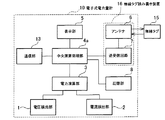
図1は本発明の実施例1に係る電子式電力量計の構成を示すブロック図である。図1に示すように、本発明の実施例1に係る電子式電力量計10は、電圧検出部1、電流検出部2、電力演算部3、中央演算処理部4、表示部5、アンテナ6、送受信回路7、記憶部8で構成されている。また、アンテナ6と送受信回路7とで、無線タグ読み書き装置16を構成している。
FIG. 1 is a block diagram showing a configuration of an electronic watt-hour meter according to Embodiment 1 of the present invention. As shown in FIG. 1, an electronic watt-hour meter 10 according to Embodiment 1 of the present invention includes a voltage detection unit 1, a current detection unit 2, a power calculation unit 3, a central calculation processing unit 4, a
電圧検出部1は電線の電圧を検出し、電流検出部2は電線を流れる電流を検出する。電力演算部3は、電圧検出部1で検出された電圧及び電流検出部2で検出された電流に基づいて電力を演算し、中央演算処理部4は、電力演算部3で演算された電力を積算して電力量を算出する。算出された電力量を示す電力量データは、記憶部8に記憶される。
The voltage detector 1 detects the voltage of the electric wire, and the current detector 2 detects the current flowing through the electric wire. The power calculation unit 3 calculates power based on the voltage detected by the voltage detection unit 1 and the current detected by the current detection unit 2, and the central processing unit 4 calculates the power calculated by the power calculation unit 3. Accumulate and calculate the amount of power. The power amount data indicating the calculated power amount is stored in the
無線タグ読み書き装置16の送受信回路7は、無線タグ読取り信号をアンテナ6を介して、無線タグ15に無線送信して、無線タグ15からの応答信号をアンテナ6を介して受信する。この無線タグ読取り信号は、無線タグ15に記憶された識別IDを要求するための信号である。応答信号は、無線タグ15が無線タグ読取り信号に応答して送信する無線タグ15の識別IDである。
The transmission / reception circuit 7 of the wireless tag read / write device 16 wirelessly transmits a wireless tag read signal to the
無線タグ読み書き装置16は、送受信回路7により、無線タグ15に無線タグ読取り信号を送信し、無線タグ15からの応答信号を受信することで、無線タグ15の識別ID(本発明の第1識別情報)を読み取る。
The wireless tag read / write device 16 transmits a wireless tag read signal to the
記憶部8は、中央演算処理部4により算出された電力量を示す電力量データとともに、無線タグ読み書き装置16により読み取られた無線タグ15の識別IDと照合されるべき特定の識別ID(本発明の第2識別情報)を記憶する。中央演算処理部4は、無線タグ読み書き装置16により読み取られた無線タグ15の識別IDと記憶部8に記憶された識別IDとを照合する。
The
中央演算処理部4は、無線タグ読み書き装置16により読み取られた識別IDが記憶部8に記憶された識別IDと一致した場合(以降、無線タグ15を検出したという)、表示部5に、中央演算処理部4により算出された電力量に基づく検針用の指示値を表示させる。 When the identification ID read by the wireless tag reader / writer 16 matches the identification ID stored in the storage unit 8 (hereinafter referred to as detecting the wireless tag 15), the central processing unit 4 An indication value for meter reading based on the electric energy calculated by the arithmetic processing unit 4 is displayed.
なお、無線タグ読み書き装置16が無線タグ15を検出したときに、該無線タグ15の識別ID及び検出時刻を記憶部8に記憶することもできる。また、このときに無線読み書き装置16は、該無線タグ15の図示しないメモリに、検針が行なわれた電力量計の識別IDや検針した月日時刻等の情報を書き込むことができる。このように、無線タグ15のメモリに電力量計の識別IDや検針した月日時刻を記憶することにより、無線タグ15に検針員の業務記録をとることができる。
When the wireless tag read / write device 16 detects the
図2は本発明の実施例1に係る電子式電力量計10及び無線タグ15を利用した応答検針システムを示す図であり、図3は本発明の実施例1に係る電子式電力量計10の動作を示すフローチャートである。
FIG. 2 is a view showing a response meter-reading system using the electronic watt-hour meter 10 and the
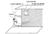
図2に示すように、本発明の実施例1に係る電子式電力量計10は、無線タグ通信可能エリア11内に無線タグ読取り信号を送信している。この無線タグ通信可能エリア11は、無線タグ読み書き装置16が無線タグ15の識別IDを読み取ることができる範囲であり、検針員9が電子式電力量計10の検針作業時に使う作業エリアと略同一の範囲になるように設定される。検針員9は、電子式電力量計10の指示値を記憶するためのハンディターミナル14a及び記憶部8に記憶された識別IDと一致する識別IDが記憶された無線タグ15を携帯している。
As shown in FIG. 2, the electronic watt-hour meter 10 according to the first embodiment of the present invention transmits a wireless tag reading signal in the wireless
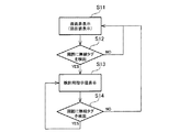
次に、図2及び図3を用いて、本発明の実施例1に係る電子式電力量計の動作を詳細に説明する。無線タグ15を携帯した検針員9が電子式電力量計10の無線タグ読み書き装置16の無線タグ通信可能エリア11外にいる場合、表示部5は、画面非表示状態または現在の指示値を表示している(ステップS11)。
Next, the operation of the electronic watt-hour meter according to the first embodiment of the present invention will be described in detail with reference to FIGS. 2 and 3. When the meter reader 9 carrying the
無線タグ15を携帯した検針員9が電子式電力量計10の無線タグ読み書き装置16の無線タグ通信可能エリア11内に入ったとき、無線タグ読み書き装置16は無線タグ15を検出し(ステップS12)、表示部5は検針用の指示値を表示する(ステップS13)。
When the meter reader 9 carrying the
無線タグ15を携帯した検針員9が無線タグ読み書き装置16の無線タグ通信可能エリア11外に出て、無線タグ読み書き装置16が無線タグ15を検出しなくなった場合、表示部5は、画面非表示状態または現在の指示値表示に戻る(ステップS14)。
When the meter reader 9 carrying the
このように、本発明の実施例1に係る電子式電力量計は、無線タグ読み書き装置16が、無線タグ通信可能エリア11内にある無線タグ15に記憶された識別IDを読み取り、中央演算処理部4は、無線タグ読み書き装置16により読み取られた識別IDと記憶部8に記憶された識別IDとを照合し、無線タグ読み書き装置16により読み取られた識別IDと記憶部8に記憶された識別IDとが一致したときに、表示部5に検針用の指示値を表示させるので、無線タグ15を携帯した検針員9が無線タグ通信可能エリア11内にいる検針業務時のみに表示部5は検針用の指示値を表示する。
As described above, in the electronic watt hour meter according to the first embodiment of the present invention, the wireless tag read / write device 16 reads the identification ID stored in the
このため、電力量計の指示値確認を悪用した空巣犯罪を防止することができる。また、現在計量画面と検針用の指示値画面とを常に交互に表示させる必要が無くなり、検針業務に合わせ効率よく必要な画面表示を行うことができる。 For this reason, it is possible to prevent a nest crime that abuses the indication value confirmation of the electricity meter. Further, it is not necessary to always display the current measurement screen and the meter reading instruction value screen alternately, and the necessary screen display can be efficiently performed according to the meter reading operation.
本発明の実施例2に係る電子式電力量計は、無線タグを携帯した検針員が近づいたときに、外部の検針用機器からの検針データ回収要求を受け付けるデータ回収モードを有効にすることを特徴とする。 The electronic watt-hour meter according to the second embodiment of the present invention enables a data collection mode for accepting a meter reading data collection request from an external meter-reading device when a meter reader carrying a wireless tag approaches. Features.
図4は本発明の実施例2に係る電子式電力量計の構成を示すブロック図である。図4に示すように、実施例2に係る電子式電力量計10は、通信部13を備えている。その他の構成は、図1に示す実施例1に係る電子式電力量計10の構成と同一であり、重複する説明は省略する。
FIG. 4 is a block diagram showing a configuration of an electronic watt-hour meter according to Embodiment 2 of the present invention. As shown in FIG. 4, the electronic watt-hour meter 10 according to the second embodiment includes a
中央演算処理部4aは、無線タグ読み書き装置16により読み取られた識別IDが記憶部8に記憶された識別IDと一致した場合、外部の検針用機器(例えば、ハンディターミナル)からのデータ回収要求を受け付けるデータ回収モードを有効にするための信号を通信部13に出力する。
When the identification ID read by the wireless tag read / write device 16 matches the identification ID stored in the
通信部13は、検針用機器と接続され、データ回収モードが有効であるときに、検針用機器からのデータ回収要求を受け付け、記憶部8に記憶された電力量データを検針用機器に送信する。
The
図5は本発明の実施例2に係る電子式電力量計10及び無線タグ15を利用した応答検針システムを示す図であり、図6は本発明の実施例2に係る電子式電力量計10の動作を示すフローチャートである。
FIG. 5 is a view showing a response meter-reading system using the electronic watt-hour meter 10 and the
図5に示すように、本発明の実施例2に係る電子式電力量計10は、無線タグ通信可能エリア11内に無線タグ読取り信号を送信している。検針員9は、電子式電力量計10の指示値を通信により回収するためのハンディターミナル14b及び記憶部8に記憶された識別IDと一致する識別IDが記憶された無線タグ15を携帯している。ハンディターミナル14bはケーブル12を介して電力量計10に接続される。
As shown in FIG. 5, the electronic watt-hour meter 10 according to the second embodiment of the present invention transmits a wireless tag reading signal in the wireless
次に、図5及び図6を用いて、本発明の実施例2に係る電子式電力量計の動作を詳細に説明する。無線タグ15を携帯した検針員9が電子式電力量計10の無線タグ読み書き装置16の無線タグ通信可能エリア11外にいる場合、電子式電力量計10は通常モードである(ステップS21)。この通常モードでは電子式電力量計10とハンディターミナル14bとの間で通信を行うことができない。
Next, the operation of the electronic watt-hour meter according to the second embodiment of the present invention will be described in detail with reference to FIGS. 5 and 6. When the meter reader 9 carrying the
無線タグ15を携帯した検針員9が電子式電力量計10の無線タグ読み書き装置16の無線タグ通信可能エリア11内に入ったとき、無線タグ読み書き装置16は無線タグ15を検出し(ステップS22)、電子式電力量計10のデータ回収モードが有効になる(ステップS23)。
When the meter reader 9 carrying the
無線タグ15を携帯した検針員9が無線タグ読み書き装置16の無線タグ通信可能エリア外に出て、無線タグ読み書き装置16が無線タグ15を検出しなくなった場合、電子式電力量計10は、通常モードに戻る(ステップS24)。
When the meter reader 9 carrying the
このように、本発明の実施例2に係る電子式電力量計は、無線タグ読み書き装置16が、無線タグ通信可能エリア11内にある無線タグ15に記憶された識別IDを読み取り、中央演算処理部4aは、無線タグ読み書き装置16により読み取られた識別IDと記憶部8に記憶された識別IDとを照合し、無線タグ読み書き装置16により読み取られた識別IDと記憶部8に記憶された識別IDとが一致したときに、データ回収モードが有効にするので、検針業務時に、無線タグ15を携帯した検針員9が無線タグ通信可能エリア11内に入ることで、スイッチ等の操作なしにデータ回収モードを有効にすることができ、データ回収作業の効率が上がる。
As described above, in the electronic watt hour meter according to the second embodiment of the present invention, the wireless tag read / write device 16 reads the identification ID stored in the
なお、実施例1の電子式電力量計10に通信部13を設け、実施例2の動作と同様に動作させることで、実施例1においても実施例2の効果と同様の効果を得ることができる。
In addition, the same effect as the effect of Example 2 can be obtained also in Example 1 by providing the
本発明は、電力量を計量する電子式電力量計として、さまざまな需要家において、利用可能である。 The present invention can be used by various consumers as an electronic watt-hour meter for measuring electric power.
1…電圧検出部
2…電流検出部
3…電力演算部
4、4a…中央演算処理部
5…表示部
6…アンテナ
7…送受信回路
8…記憶部
9…検針員
10…電子式電力量計
11…無線タグ通信可能エリア
12…ケーブル
13…通信部
14a、14b…ハンディターミナル
15…無線タグ
16…無線タグ読み書き装置
DESCRIPTION OF SYMBOLS 1 ... Voltage detection part 2 ... Current detection part 3 ... Electric
Claims (3)
前記電線を流れる電流を検出する電流検出部と、
前記電圧検出部で検出された電圧及び前記電流検出部で検出された電流に基づいて、電力を演算し、該電力を積算して電力量を算出する処理部と、
前記処理部で算出された電力量に基づく検針用の指示値を表示する表示部と、
所定範囲内にある無線タグとの間で信号を送受信することにより、前記無線タグに記憶された第1識別情報を読み取るための無線タグ読み書き装置と、
前記無線タグ読み書き装置により読み取られた前記第1識別情報と照合されるべき第2識別情報が記憶された記憶部と、
を備え、
前記処理部は、
前記無線タグ読み書き装置により読み取られた前記第1識別情報と前記記憶部に記憶された前記第2識別情報とを照合し、前記第1識別情報と前記第2識別情報とが一致したときに、前記表示部に前記検針用の指示値を表示させることを特徴とする電子式電力量計。 A voltage detector for detecting the voltage of the electric wire;
A current detector for detecting a current flowing through the wire;
A processing unit that calculates power based on the voltage detected by the voltage detection unit and the current detected by the current detection unit, and calculates the amount of power by integrating the power;
A display unit for displaying an instruction value for meter reading based on the electric energy calculated by the processing unit;
A wireless tag read / write device for reading first identification information stored in the wireless tag by transmitting / receiving a signal to / from a wireless tag within a predetermined range;
A storage unit storing second identification information to be checked against the first identification information read by the wireless tag read / write device;
With
The processor is
When the first identification information read by the wireless tag read / write device and the second identification information stored in the storage unit are collated, and the first identification information and the second identification information match, An electronic watt-hour meter that displays the reading value for meter reading on the display unit.
前記電線を流れる電流を検出する電流検出部と、
前記電圧検出部で検出された電圧及び前記電流検出部で検出された電流に基づいて、電力を演算し、該電力を積算して電力量を算出する処理部と、
所定範囲内にある無線タグとの間で信号を送受信することにより、前記無線タグに記憶された第1識別情報を読み取るための無線タグ読み書き装置と、
前記処理部で算出された電力量を示す電力量データ及び前記無線タグ読み書き装置により読み取られた前記第1識別情報と照合されるべき第2識別情報が記憶された記憶部と、
外部の検針用機器が接続され、前記検針用機器からのデータ回収要求を受け付けるデータ回収モードが有効であるときに、前記記憶部に記憶された電力量データを前記検針用機器に送信する通信部と、
を備え、
前記処理部は、
前記無線タグ読み書き装置により読み取られた前記第1識別情報と前記記憶部に記憶された前記第2識別情報とを照合し、前記第1識別情報と前記第2識別情報とが一致したときに、前記データ回収モードを有効にするための信号を前記通信部に出力することを特徴とする電子式電力量計。 A voltage detector for detecting the voltage of the electric wire;
A current detector for detecting a current flowing through the wire;
A processing unit that calculates power based on the voltage detected by the voltage detection unit and the current detected by the current detection unit, and calculates the amount of power by integrating the power;
A wireless tag read / write device for reading first identification information stored in the wireless tag by transmitting / receiving a signal to / from a wireless tag within a predetermined range;
A storage unit that stores power amount data indicating the amount of power calculated by the processing unit and second identification information to be collated with the first identification information read by the wireless tag read / write device;
A communication unit that transmits power amount data stored in the storage unit to the meter-reading device when an external meter-reading device is connected and a data recovery mode for receiving a data recovery request from the meter-reading device is valid When,
With
The processor is
When the first identification information read by the wireless tag read / write device and the second identification information stored in the storage unit are collated, and the first identification information and the second identification information match, An electronic watt-hour meter that outputs a signal for enabling the data recovery mode to the communication unit.
前記無線タグ読み書き装置により読み取られた前記第1識別情報と照合されるべき前記第2識別情報とともに前記処理部で算出された電力量を示す電力量データを記憶し、
外部の検針用機器に接続され、前記検針用機器からのデータ回収要求を受け付けるデータ回収モードが有効であるときに、前記記憶部に記憶された電力量データを前記検針用機器に送信する通信部を更に備え、
前記処理部は、
前記無線タグ読み書き装置により読み取られた前記第1識別情報と前記記憶部に記憶された前記第2識別情報とを照合し、前記第1識別情報と前記第2識別情報とが一致したときに、前記表示部に前記検針用の指示値を表示させるとともに前記データ回収モードを有効にするための信号を前記通信部に出力することを特徴とする請求項1記載の電子式電力量計。
The storage unit
Storing power amount data indicating the amount of power calculated by the processing unit together with the second identification information to be checked against the first identification information read by the wireless tag read / write device;
A communication unit that is connected to an external meter-reading device and transmits power amount data stored in the storage unit to the meter-reading device when a data recovery mode for receiving a data recovery request from the meter-reading device is valid Further comprising
The processor is
When the first identification information read by the wireless tag read / write device and the second identification information stored in the storage unit are collated, and the first identification information and the second identification information match, The electronic watt-hour meter according to claim 1, wherein an indication value for meter reading is displayed on the display unit and a signal for enabling the data collection mode is output to the communication unit.
Priority Applications (1)
| Application Number | Priority Date | Filing Date | Title |
|---|---|---|---|
| JP2005054988A JP2006242598A (en) | 2005-02-28 | 2005-02-28 | Electronic energy meter |
Applications Claiming Priority (1)
| Application Number | Priority Date | Filing Date | Title |
|---|---|---|---|
| JP2005054988A JP2006242598A (en) | 2005-02-28 | 2005-02-28 | Electronic energy meter |
Publications (1)
| Publication Number | Publication Date |
|---|---|
| JP2006242598A true JP2006242598A (en) | 2006-09-14 |
Family
ID=37049178
Family Applications (1)
| Application Number | Title | Priority Date | Filing Date |
|---|---|---|---|
| JP2005054988A Pending JP2006242598A (en) | 2005-02-28 | 2005-02-28 | Electronic energy meter |
Country Status (1)
| Country | Link |
|---|---|
| JP (1) | JP2006242598A (en) |
Cited By (2)
| Publication number | Priority date | Publication date | Assignee | Title |
|---|---|---|---|---|
| CN104065385A (en) * | 2013-03-20 | 2014-09-24 | 凌通科技股份有限公司 | Signal decoding circuit applied to wireless charging or radio frequency identification system |
| JP2015141030A (en) * | 2014-01-27 | 2015-08-03 | 中国電力株式会社 | Power meter indication number display system |
Citations (6)
| Publication number | Priority date | Publication date | Assignee | Title |
|---|---|---|---|---|
| JPH06282545A (en) * | 1993-03-30 | 1994-10-07 | Hitachi Ltd | Document processing method |
| JP2001349910A (en) * | 2000-06-07 | 2001-12-21 | Toshiba Corp | Watt hour meter, watt hour meter system, and power supply system |
| JP2002074570A (en) * | 2000-08-28 | 2002-03-15 | Yoshiomi Yamada | Metering instrument, and device/system for reading meter |
| JP2003228618A (en) * | 2002-02-06 | 2003-08-15 | Toppan Printing Co Ltd | Periodic patrol business management method using non-contact IC tag |
| JP2004340857A (en) * | 2003-05-19 | 2004-12-02 | Toshiba Corp | How to display the weighing status of the watt hour meter |
| JP2004361242A (en) * | 2003-06-04 | 2004-12-24 | Toshiba Corp | Alarm system and watt hour meter using watt hour meter |
-
2005
- 2005-02-28 JP JP2005054988A patent/JP2006242598A/en active Pending
Patent Citations (6)
| Publication number | Priority date | Publication date | Assignee | Title |
|---|---|---|---|---|
| JPH06282545A (en) * | 1993-03-30 | 1994-10-07 | Hitachi Ltd | Document processing method |
| JP2001349910A (en) * | 2000-06-07 | 2001-12-21 | Toshiba Corp | Watt hour meter, watt hour meter system, and power supply system |
| JP2002074570A (en) * | 2000-08-28 | 2002-03-15 | Yoshiomi Yamada | Metering instrument, and device/system for reading meter |
| JP2003228618A (en) * | 2002-02-06 | 2003-08-15 | Toppan Printing Co Ltd | Periodic patrol business management method using non-contact IC tag |
| JP2004340857A (en) * | 2003-05-19 | 2004-12-02 | Toshiba Corp | How to display the weighing status of the watt hour meter |
| JP2004361242A (en) * | 2003-06-04 | 2004-12-24 | Toshiba Corp | Alarm system and watt hour meter using watt hour meter |
Cited By (3)
| Publication number | Priority date | Publication date | Assignee | Title |
|---|---|---|---|---|
| CN104065385A (en) * | 2013-03-20 | 2014-09-24 | 凌通科技股份有限公司 | Signal decoding circuit applied to wireless charging or radio frequency identification system |
| CN104065385B (en) * | 2013-03-20 | 2017-11-17 | 凌通科技股份有限公司 | Signal decoding circuit applied to wireless charging or radio frequency identification system |
| JP2015141030A (en) * | 2014-01-27 | 2015-08-03 | 中国電力株式会社 | Power meter indication number display system |
Similar Documents
| Publication | Publication Date | Title |
|---|---|---|
| KR101037433B1 (en) | Wireless communication system for underground facility management | |
| EP2480862B1 (en) | Telemetry system | |
| KR100937257B1 (en) | Telemetering information identifing system using wire and wireless telecommunication technology | |
| US9338411B2 (en) | System and method for remote utility meter reading | |
| US20070075873A1 (en) | Location awareness system using rfid and wireless connectivity apparatus for location awareness system used therein | |
| KR101768679B1 (en) | Wireless remote meter reading system capable of real-time monitoring | |
| ITTO970883A1 (en) | DETECTION SYSTEM FOR DOMESTIC CONSUMPTION OF ELECTRICITY, THERMAL ENERGY, WATER AND GAS. | |
| EP4121920B1 (en) | Programming electric meter global positioning system coordinates using smart device | |
| KR101022763B1 (en) | Meter that stores data, wireless remote meter reading system and control method using same | |
| JP5476602B2 (en) | Portable information terminal used in gas meter remote management system | |
| US11255882B2 (en) | Monitoring an energy parameter in a distribution station | |
| JP2004005317A (en) | Management meter and management system | |
| GB2374760A (en) | Transmitting utility meter measurements by mobile telephone | |
| KR100416926B1 (en) | Both transformer power load monitoring and watt meter reading remote control system | |
| JP2006242598A (en) | Electronic energy meter | |
| KR20140014816A (en) | Electric power use informaion notification system | |
| KR20210004409A (en) | Autonomous integrated remote meter reading and fare notification system | |
| KR101627963B1 (en) | Water consumption automatic check system and method thereof | |
| KR20050012572A (en) | Method and System for Reducing Power Consumption of Wireless Modem for Use in Telemetering System | |
| KR20130118070A (en) | System for menagement of facilities using rfid | |
| KR101127352B1 (en) | Remote water metering system using gps | |
| JP2019030138A (en) | Watt-hour meter | |
| JP3375231B2 (en) | Wireless meter reading system | |
| KR101814592B1 (en) | Transmitter of remote metering system and method for driving the same | |
| JP4931191B2 (en) | Remote meter reading system for measuring instrument |
Legal Events
| Date | Code | Title | Description |
|---|---|---|---|
| A621 | Written request for application examination |
Free format text: JAPANESE INTERMEDIATE CODE: A621 Effective date: 20071203 |
|
| A711 | Notification of change in applicant |
Free format text: JAPANESE INTERMEDIATE CODE: A712 Effective date: 20100303 |
|
| A131 | Notification of reasons for refusal |
Free format text: JAPANESE INTERMEDIATE CODE: A131 Effective date: 20101124 |
|
| A02 | Decision of refusal |
Free format text: JAPANESE INTERMEDIATE CODE: A02 Effective date: 20110322 |