JP2006257532A - Method for measuring potential of corrosion-prevented body by cathodic protection, device for measuring potential, cathodic protection method and device - Google Patents
Method for measuring potential of corrosion-prevented body by cathodic protection, device for measuring potential, cathodic protection method and device Download PDFInfo
- Publication number
- JP2006257532A JP2006257532A JP2005080350A JP2005080350A JP2006257532A JP 2006257532 A JP2006257532 A JP 2006257532A JP 2005080350 A JP2005080350 A JP 2005080350A JP 2005080350 A JP2005080350 A JP 2005080350A JP 2006257532 A JP2006257532 A JP 2006257532A
- Authority
- JP
- Japan
- Prior art keywords
- potential
- power source
- anticorrosion
- protected
- measuring
- Prior art date
- Legal status (The legal status is an assumption and is not a legal conclusion. Google has not performed a legal analysis and makes no representation as to the accuracy of the status listed.)
- Pending
Links
Images


Landscapes
- Prevention Of Electric Corrosion (AREA)
Abstract
Description
本発明は、外部電源方式の電気防食における被防食体の電位測定方法、電気防食方法及び装置に関する。 The present invention relates to a method for measuring a potential of an object to be protected in an external power source type of anticorrosion, an anticorrosion method, and an apparatus.
腐食環境下に置かれた被防食体に外部電源方式の防食を施した場合、当該被防食体が適正に防食されているかどうかを把握する必要がある。この防食の達成状況の把握は、防食電位や防食電流密度に基づく判定により行われることが多く、種々の規格において防食達成電位等が提唱されている。 When an external power source type anticorrosion is applied to an object to be protected placed in a corrosive environment, it is necessary to know whether or not the object to be protected is appropriately protected. Grasping of the achievement status of the anticorrosion is often performed by determination based on the anticorrosion potential or the anticorrosion current density, and various standards have proposed the anticorrosion achievement potential.
ところで、海水中のように電気伝導度の高い(低抵抗の)腐食環境に置かれた被防食体については、ある程度正確に防食電位を測定することができるため、防食達成状況の把握が可能であるが、土壌、コンクリート又は淡水中等のように電気伝導度の低い(高抵抗の)腐食環境に置かれた被防食体については、通電時のオーム降下(IR降下)が電極電位に加算されてしまい、正確な防食電位の測定が困難となるため、防食達成状況の把握が正確に行えない問題がある。また、このような電気伝導度の低い腐食環境に置かれた被防食体は、不可視であったり、表面に塗覆装がなされていることが多く、被防食体の表面積を正確に求めることができないため、全防食電流は測定できても電流密度への換算ができず、防食電流密度に基づく判定も困難となる。 By the way, it is possible to measure the corrosion protection potential of corrosion-protected bodies placed in corrosive environments with high electrical conductivity (low resistance) such as in seawater, so it is possible to grasp the status of corrosion prevention. However, for an object to be protected placed in a corrosive environment with low electrical conductivity (high resistance) such as soil, concrete, or fresh water, the ohmic drop (IR drop) during energization is added to the electrode potential. Therefore, since it is difficult to accurately measure the anticorrosion potential, there is a problem that the anticorrosion achievement status cannot be accurately grasped. Moreover, the to-be-protected object placed in such a corrosive environment with low electrical conductivity is often invisible or coated on the surface, and the surface area of the to-be-protected object can be accurately obtained. Therefore, even if the total anticorrosion current can be measured, it cannot be converted into a current density, and determination based on the anticorrosion current density becomes difficult.
防食電位や防食電流密度による判定に代えて、電気防食の通電(オン)状態から通電を切った(オフ)状態に移行した直後の電位値(インスタントオフ電位)と、オフ後十分に時間経過後の電位(オフ電位)の両者を求め、インスタントオフ電位とオフ電位の差(シフト値)から防食達成状況を把握することが広く行われ、工業規格等でも採用されてきた(下記非特許文献1参照)。シフト値の算出において、最大の問題はインスタントオフ電位の計測にある。刻々と変化するオフ電位に対して読みとりまでの時間についての許容量が明確でなく、そのため読みとり値は個人差も大きかった。また、下記非特許文献2のように、オシロスコープなど高速記録媒体による測定も提案されているが、現場測定に不向きであり、実用化されていない。
Instead of the judgment based on the anticorrosion potential and the anticorrosion current density, the potential value (instant-off potential) immediately after transition from the energization (on) state of the anticorrosion to the off (off) state, and a sufficient amount of time after the off time It has been widely used to obtain the anti-corrosion achievement status from the difference between the instant-off potential and the off-potential (shift value), and has been adopted in industrial standards and the like (the following non-patent document 1) reference). In calculating the shift value, the biggest problem is the measurement of the instant-off potential. The permissible amount of time until reading with respect to the off-potential that changes every moment is not clear, and therefore the reading value varies greatly among individuals. Further, as described in Non-Patent
一方、下記特許文献1、2のように、直流電源装置の防食電流に含まれる交流成分を利用し、照合電極で検出された被防食体の電位からオーム降下誤差を除去し、得られる防食電位に基づいて電気防食を行う技術が提案されている。
On the other hand, as disclosed in
しかしながら、これらの技術は、測定されるオーム降下が電源回路に内蔵される平滑回路に依存するという欠点を有している。また、低水分下の土壌やコンクリート中の鋼材で界面に存在する電気化学的時定数が小さい場合には、測定値に誤差を生じやすい。 However, these techniques have the disadvantage that the measured ohmic drop depends on a smoothing circuit built into the power supply circuit. Moreover, when the electrochemical time constant which exists in an interface with the soil under low moisture and the steel in concrete is small, it is easy to produce an error in a measured value.
本発明は、前記課題に鑑みてなされたものであり、外部電源方式の電気防食における被防食体の電位を正確に測定することができる、被防食体の電位測定方法、電気防食方法及び装置を提供することを目的とする。 The present invention has been made in view of the above-described problems, and provides a method for measuring the potential of a corrosion-protected body, a method for preventing corrosion, and a device capable of accurately measuring the potential of the corrosion-protected body in the external power source type of corrosion protection. The purpose is to provide.
本発明は、外部電源方式の電気防食における被防食体の電位測定方法であって、電源の陽極端子に陽極を導通可能に接続するとともに、被防食体を陰極として前記電源の陰極端子に導通可能に接続し、前記電源から供給する電流を制御用パルス波で繰り返しオンオフ制御しながら前記陽極と前記被防食体との間に通電し、制御されたパルス電流のオフ時に同期させて前記被防食体の電位を測定する被防食体の電位測定方法を提供することにより、前記目的を達成したものである。 The present invention relates to a method for measuring the potential of an object to be corroded in an external power source type electric corrosion protection, and is capable of electrically connecting an anode to an anode terminal of a power source and capable of conducting to an anode terminal of the power source using the object to be corroded as a cathode. The current to be supplied from the power source is energized between the anode and the subject to be corroded while being repeatedly turned on / off by a control pulse wave, and is synchronized with the controlled pulse current being turned off. The object is achieved by providing a method for measuring the potential of an anticorrosive to measure the potential.
また、本発明は、上記本発明の被防食体の電位測定方法を実施するための電位測定装置であって、防食用電源から供給される防食電流を制御用パルス波に基づいて前記電源から供給される防食電流をオンオフ制御する制御部と、前記電源の陰極端子に導通可能に接続された被防食体の電位を制御されたパルス電流のオフ時に同期して計測する電位計測部とを備えている電位測定装置を提供することにより、上記目的を達成したものである。 Further, the present invention is a potential measuring device for carrying out the above-described method for measuring a potential of an object to be protected according to the present invention, wherein an anticorrosion current supplied from an anticorrosion power supply is supplied from the power supply based on a control pulse wave. A control unit that controls the on / off of the anticorrosive current, and a potential measurement unit that measures the potential of the corrosion-protected body connected to the cathode terminal of the power source in a synchronized manner when the controlled pulse current is off. The above object is achieved by providing a potential measuring device.
また、本発明は、上記本発明の被防食体の電位測定方法で測定された前記被防食体の電位を制御電位として防食印可電圧を設定し、防食を行う電気防食方法を提供することにより、上記目的を達成したものである。 In addition, the present invention provides an anticorrosion method for performing anticorrosion by setting an anticorrosion applied voltage with the potential of the above-mentioned anticorrosive body measured by the above-described method for measuring the potential of the above-described anticorrosive body as a control potential, The above objective has been achieved.
また、本発明は、上記本発明の電気防食方法を実施するための装置であって、防食用電源と、該電源の陽極端子に導通可能に接続された陽極と、制御用パルス波に基づいて前記電源から供給される防食電流をオンオフ制御する制御部と、前記電源の陰極端子に導通可能に接続された陰極の電位を制御されたパルス電流のオフ時に同期して計測する電位計測部とを備えている電気防食装置を提供することにより、上記目的を達成したものである。 Further, the present invention is an apparatus for carrying out the above-described cathodic protection method of the present invention, based on an anticorrosion power source, an anode communicatively connected to the anode terminal of the power source, and a control pulse wave. A control unit for controlling on / off of the anticorrosion current supplied from the power source, and a potential measuring unit for measuring the potential of the cathode connected to the cathode terminal of the power source in a conductive manner in synchronization with the controlled pulse current being turned off. The object is achieved by providing an electro-corrosion protection device.
また、本発明は、外部電源方式により電気防食を行うときに使用する陰極電位の測定方法であって、入力される交流を整流し且つ平滑化せずに出力する電源の陽極端子に陽極を導通可能に接続するとともに、被防食体を陰極として前記電源の陰極端子に導通可能に接続し、前記電源で前記陽極と前記被防食体との間に通電しながら、前記交流に対応する出力のゼロクロス時に同期させて前記陰極の電位を測定する陰極電位の測定方法を提供することにより、上記目的を達成したものである。 The present invention also relates to a method for measuring a cathode potential used when cathodic protection is performed by an external power supply system, wherein the anode is connected to the anode terminal of a power supply that outputs the AC without rectifying and smoothing the input AC. And connecting to the cathode terminal of the power source as a cathode to be protected, and energizing between the anode and the to-be-protected body with the power source, and an output zero cross corresponding to the alternating current The above object is achieved by providing a cathode potential measuring method for measuring the cathode potential in synchronization with each other.
また、本発明は、上記本発明の被防食体の電位測定方法で測定された被防食体の電位を制御電位として防食印可電圧を設定し、防食を行う電気防食方法を提供することにより、上記目的を達成したものである。 In addition, the present invention provides an anticorrosion method for setting the anticorrosion applied voltage using the potential of the corroded body measured by the above-described method for measuring the potential of the corroded body of the present invention as a control potential, and performing anticorrosion. The goal has been achieved.
上記本発明の電気防食方法を実施するための装置であって、入力される交流を整流し且つ平滑化せずに出力する防食用電源と、該電源の陽極端子に導通可能に接続された陽極と、前記電源の陰極端子に導通可能に接続された被防食体の電位を前記交流に対応する出力のゼロクロス時に同期して計測する電位計測部とを備えている電気防食装置を提供することにより、上記目的を達成したものである。 An apparatus for carrying out the above-described electrocorrosion protection method of the present invention, wherein the input AC is rectified and output without being smoothed, and the anode connected to the anode terminal of the power supply in a conductive manner And an electric corrosion protection device comprising a potential measurement unit that measures the potential of the object to be protected connected to the cathode terminal of the power source in a conductive manner at the time of zero crossing of the output corresponding to the alternating current. The above-mentioned purpose has been achieved.
本発明によれば、高抵抗環境下の被防食体に電気防食を行いつつオーム降下分を除いた被防食体の電位測定を行うことができ、該電位に基づいて効果的に電気防食を行うことができる。 ADVANTAGE OF THE INVENTION According to this invention, it is possible to measure the potential of the body to be corroded while removing the ohmic drop while performing the electrical corrosion protection on the body to be corroded in a high resistance environment, and to effectively perform the electrical corrosion protection based on the potential. be able to.
以下、本発明を、その好ましい実施の形態に基づいて説明する。 Hereinafter, the present invention will be described based on preferred embodiments thereof.
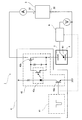
図1は、本発明の電気防食装置の第1実施形態を模式的に示したものである。図1において、符号1は電気防食装置を示している。
FIG. 1 schematically shows a first embodiment of the cathodic protection device of the present invention. In FIG. 1, the code |
図1に示すように、本実施形態の電気防食装置1は、防食用電源2と、電源2の陽極端子21に導通可能に接続された陽極3と、制御用パルス波に基づいて電源2から供給される防食電流をオンオフ制御する制御部4と、電源2の陰極端子22に導通可能に接続された被防食体5の電位を制御されたパルス電流のオフ時に同期して計測する電位計測部6とを備えている。
As shown in FIG. 1, the
防食用電源2及び陽極3は、被防食体5及び被防食体5が配される腐食環境に応じて選択される。
The
制御部4は、制御信号となるパルス波を発生させる制御用パルス信号発生部41と、防食電流をオンオフ制御する防食電流パルス発生部42とを備えている。制御用パルス信号発生部41は、パルスジェネレータ等が好ましい。防食電流パルス発生部42は、制御用パルス信号発生部41の出力部に接続されるトランジスタ42aと、電源2の陽極端子21と陽極3との間に流れる電流を制御する電界効果型トランジスタ(FET)42bと、トランジスタ42aとFET42bとの間を絶縁状態で接続するフォトカプラ42cとを備えており、制御用パルス信号発生部41で発生したパルス波に基づいて電源2から供給される防食電流をオンオフ制御する。
The
電位計測部6は、被防食体5の近傍に配される照合電極61と、制御されたパルス電流のオフ時に同期して被防食体5の電位(インスタントオフ電位)の値を保持する電位保持回路とを備えている。該電位保持回路には、ピークホールド回路(ネガティブピークホールド回路)、サンプルホールド回路等が用いられる。照合電極61は被防食体及び該被防食体が配される腐食環境に応じて選択される。
The
次に、上記電気防食装置1における被防食体5の電位の測定及び該電位を用いた電気防食方法について説明する。
Next, the measurement of the potential of the
先ず、図1に示すように電気防食装置1をセットし、防食用電源2の陽極端子21に陽極3を制御部4を介して導通可能に接続するとともに、被防食体5を陰極として電源2の陰極端子22に導通可能に接続する。
First, as shown in FIG. 1, the
次に、制御用パルス信号発生部41から発生される制御用パルス波で、電源2から供給する電流を繰り返しオンオフ制御しながら陽極3と被防食体5との間に通電し、制御されたパルス電流のオフ時に同期させて電位計測部6で被防食体5の電位(電極電位)を測定する。
Next, with the control pulse wave generated from the control pulse
前記制御されたパルス電流のオン/オフ時間比は40以上であることが好ましく、40〜200であることがより好ましい。パルス電流のオン/オフ時間比が斯かる範囲内であると、実用上、防食電流をオフすることを意識することなくインスタントオフ電位の測定が可能である。パルス電流のオフ時間は、低水分下の土壌やコンクリート中の鋼材では界面に存在する電気化学的時定数が非常に小さい場合があることや、測定ケーブルが長くなる場合もあることなどを考慮すると0.1〜10msが好ましい。また、パルス電流のオン時間は、オン/オフ時間比を可能な限り大きくすることを考慮すると4ms〜2sが好ましい。パルス電流は、矩形波であることが好ましい。 The ON / OFF time ratio of the controlled pulse current is preferably 40 or more, and more preferably 40 to 200. When the ON / OFF time ratio of the pulse current is within such a range, it is practically possible to measure the instant-off potential without being aware of turning off the anticorrosion current. In consideration of the fact that the electrochemical time constant at the interface may be very small and the measurement cable may be long in steel materials in low moisture soil or concrete, the pulse current off time 0.1 to 10 ms is preferable. Further, the on time of the pulse current is preferably 4 ms to 2 s in consideration of increasing the on / off time ratio as much as possible. The pulse current is preferably a rectangular wave.
そして、被防食体5の電位測定方法で測定された被防食体5の電位を制御電位として電源2の防食印可電圧を調節・設定し、防食を引き続き行う。電源2の防食印可電圧の調節・設定は、手動で行うこともできるし、電気的制御回路により自動化することもできる。
Then, the anticorrosion applied voltage of the
このように、本実施形態の被防食体の電位測定方法によれば、高抵抗環境下に置かれた被防食体であっても、その電気防食を行いつつオーム降下分を除いた被防食体5の正確な電位測定を繰り返し行うことができる。従って、得られた被防食体の電位が制御電位(防食電位)になるようにコントロールすることによって防食性の高い電気防食を安定的に行うことができる。 Thus, according to the method for measuring the potential of the object to be protected according to the present embodiment, even if the object to be protected is placed in a high-resistance environment, the object to be corroded is subjected to the anticorrosion and the ohm drop is removed. 5 accurate potential measurements can be repeated. Therefore, by controlling so that the potential of the obtained object to be protected becomes the control potential (corrosion protection potential), it is possible to stably perform the electrocorrosion protection with high corrosion resistance.
図2は、本発明の電気防食装置の第2実施形態を模式的に示したものである。図2において、前記第1実施形態と共通する部分については同一符号を付している。よって、特に説明のない部分については、前記第1実施形態における説明が適宜適用される。 FIG. 2 schematically shows a second embodiment of the cathodic protection device of the present invention. In FIG. 2, the same reference numerals are given to portions common to the first embodiment. Therefore, the description in the first embodiment is appropriately applied to a portion that is not particularly described.
図2に示すように、本実施形態の電気防食装置1’は、入力される交流を整流し且つ平滑化せずに出力する防食用電源2’と、電源2’の陽極端子21に導通可能に接続された陽極3、電源2’の陰極端子22に導通可能に接続された被防食体5の電位を前記交流のゼロクロス時に同期して計測する電位計測部6’と、電源2のトランスを介して前記交流のゼロクロスを検出するゼロクロス検出部7とを備えている。
As shown in FIG. 2, the
電源2’の備える整流回路で用いる整流素子はゼロクロス電位で不感域が明瞭に現れるシリコン素子が好ましく、ダイオードあるいはサイリスタなど素子が用いられる。例えば、図2に示すようなシリコンダイオードがブリッジ接続された全波整流回路が挙げられる。 The rectifying element used in the rectifying circuit provided in the power supply 2 'is preferably a silicon element in which a dead zone is clearly shown at zero cross potential, and an element such as a diode or a thyristor is used. For example, a full-wave rectifier circuit in which silicon diodes as shown in FIG.
電位計測部6’は、被防食体5の近傍に配される照合電極61と、電源2’の陰極端子22に導通可能に接続された被防食体5の電位を前記交流のゼロクロス時に同期して計測する電位計測回路とを備えている。この電位計測回路には、電位の同期計測する目的からサンプルホールド回路等が用いられる。
The
次に、上記電気防食装置1’における被防食体の電位測定及び該電位を用いた電気防食方法について説明する。 Next, a description will be given of the measurement of the potential of the object to be protected in the above-described cathodic protection device 1 'and the method of cathodic protection using the potential.
先ず、図2に示すように電気防食装置1’をセットし、防食用電源2の陽極端子21に陽極3を導通可能に接続するとともに、被防食体5を陰極として電源2の陰極端子22に導通可能に接続する。
First, as shown in FIG. 2, the
次に、前記電源2’で陽極2と被防食体5との間に通電しながら、ゼロクロス検出部7からの検出出力に同期させ、前記交流のゼロクロス時に同期させて電位計測部6’で被防食体5の電極電位を測定する。
Next, while the
そして、被防食体5の電位測定方法で測定された被防食体5の電位を制御電位として電源2の防食印可電圧を調節・設定し、防食を引き続き行う。電源2の防食印可電圧の調節・設定は、手動で行うこともできるし、整流回路でサイリスタを用いている場合は点弧位置調整することにより自動化することもできる。
Then, the anticorrosion applied voltage of the
このように、本実施形態の被防食体の電位測定方法によれば、高抵抗環境下に置かれた被防食体であっても、その電気防食を行いつつオーム降下分を除いた被防食体5の正確な電位測定を繰り返し行うことができる。従って、得られた被防食体の防食電位を制御電位として被防食体5に防食印可電圧を負荷することにより、防食性の高い効果的な電気防食を安定的に行うことができる。
Thus, according to the method for measuring the potential of the object to be protected according to the present embodiment, even if the object to be protected is placed in a high-resistance environment, the object to be corroded is subjected to the anticorrosion and the ohm drop is removed. 5 accurate potential measurements can be repeated. Therefore, effective anticorrosion with high anticorrosion property can be stably performed by applying the anticorrosion applied voltage to the to-
本発明は、外部電源方式の電気防食における被防食体の電位測定方法を実施するための装置の好ましい実施形態として、前記実施形態の電気防食装置1における、制御用パルス波に基づいて電源2から供給される防食電流をオンオフ制御する制御部4と、電源2の陰極端子22に導通可能に接続された被防食体5の電位を制御されたパルス電流のオフ時に同期して計測する電位計測部6とを具備する電位測定装置を含むものであり、当該電位測定装置を既存の外部電源方式の電気防食方法における防食回路に組み込んで被防食体の電位測定及び電気防食を行うこともできる。
As a preferred embodiment of the apparatus for carrying out the method for measuring the potential of the object to be protected in the external power supply type electric corrosion prevention, the present invention is based on the control pulse wave in the electric
以下、本発明を実施例によりさらに具体的に説明する。 Hereinafter, the present invention will be described more specifically with reference to examples.
〔実施例1〕
電気防食下の水道水中の炭素鋼(被防食体)の電位を測定するために、図1の電気防食装置をセットし、電流密度350mA/m2で防食電流を流しながら、オン/オフ時間比=50(ms)/1(ms)で防食電流のスィッチングを行った。陽極には白金めっきチタン電極、照合電極には飽和甘こう電極(SCE)を用いた。図3は、そのときの被防食体の電位値(vs.SCE)の波形をオシロスコープにより計測した結果を示したものである。パルス状のピークは電流オフ時の電位値に対応している。オフ時の炭素鋼の電位は約−0.72V(vs.SCE)であった。電位計測部6に内蔵される電位保持回路を通して、オフ時間に同期する電位値を保持(HOLD)させることによって、オフ時の被防食体の電位を低速のディジタル電圧計によって十分安定に測定することができた。
[Example 1]
To measure the potential of the carbon steel in tap water under cathodic protection (the anticorrosion material), sets the cathodic protection device of FIG. 1, while flowing a corrosion current at a current density of 350mA / m 2, on / off time ratio The anticorrosion current was switched at = 50 (ms) / 1 (ms). A platinum-plated titanium electrode was used as the anode, and a saturated gypsum electrode (SCE) was used as the reference electrode. FIG. 3 shows the result of measuring the waveform of the potential value (vs. SCE) of the object to be protected at that time with an oscilloscope. The pulse-like peak corresponds to the potential value when the current is off. The potential of the carbon steel at the time of off was about −0.72 V (vs. SCE). The potential value synchronized with the OFF time is held (HOLD) through the potential holding circuit built in the
〔実施例2〕
電気防食下のコンクリート中の鉄筋(被防食体)の電位を測定するために、図1の電気防食装置をセットし、1.2Aの電流を流しながら、オン/オフ時間比=100(ms)/1(ms)で防食電流のスィッチングを行った。陽極には酸化イリジウム被覆の酸化物電極、照合電極には二酸化マンガン電極を用いた。そして、そのときの電位波形と電位計測部6に内蔵される電位保持回路で保持された電位値を図4(a)及び(b)に示す。これらの図は同一の実験条件で測定されたものであるが異なる時間幅で記録されている。(a)はオフ時間幅に合わせて短時間の記録であるのに対し、(b)は3回のスィッチングが含まれる時間幅で記録されたものである。被防食体のインスタントオフ電位はスィッチングにほとんど影響されず一定の値を示し、−1.28V(vs.MnO2)であった。
[Example 2]
In order to measure the potential of the reinforcing steel (corroded body) in concrete under cathodic protection, set the cathodic protection device of FIG. 1 and on / off time ratio = 100 (ms) while passing a current of 1.2 A. The anticorrosive current was switched at / 1 (ms). The anode was an iridium oxide-coated oxide electrode, and the reference electrode was a manganese dioxide electrode. 4A and 4B show the potential waveform at that time and the potential value held by the potential holding circuit built in the
〔実施例3〕
実施例2とは別の電気防食が適用されたコンクリート構造物において、図2の電気防食装置をセットし、コンクリート中の鉄筋について、交流電圧が0Vを示す点の近傍(ゼロクロシング)に同期させて被防食体の電位を測定した。被防食体の電位は−362mV(vs.MnO2)であった。図5は、その時の各種パラメータの波形をオシロスコープにより計測した結果を示したものである。交流のゼロクロシングに同期させて計測された被防食体の電位は、防食電流0の時の被防食体の電位と一致した。
Example 3
In the concrete structure to which the anticorrosion different from that of Example 2 is applied, the anticorrosion device of FIG. 2 is set, and the reinforcing bars in the concrete are synchronized with the vicinity of the point where the AC voltage is 0 V (zero crossing). Then, the potential of the body to be protected was measured. The potential of the body to be protected was −362 mV (vs. MnO 2 ). FIG. 5 shows the results of measuring waveforms of various parameters at that time with an oscilloscope. The potential of the corrosion-protected body measured in synchronization with alternating zero crossing coincided with the potential of the corrosion-protected body when the corrosion-proof current was zero.
本発明は、腐食環境下、特に、土壌、コンクリート、淡水等の電気伝導度の低い腐食環境下に置かれた被防食体に外部電源方式の電気防食を施すときに好適である。 INDUSTRIAL APPLICABILITY The present invention is suitable when an external power source type electric corrosion protection is applied to an object to be protected placed in a corrosive environment, particularly in a corrosive environment having low electrical conductivity such as soil, concrete, and fresh water.
1、1’ 電気防食装置
2、2’ 電源
21 陽極端子
22 陰極端子
3 陽極
4 制御部
41 制御用パルス信号発生部
42 防食電流パルス発生部
42a トランジスタ
42b 電界効果型トランジスタ
42c フォトカプラ
5 被防食体(陰極)
6、6’ 電位計測部
7 ゼロクロス検出部
DESCRIPTION OF
6, 6 'Potential measurement unit 7 Zero cross detection unit
Claims (8)
電源の陽極端子に陽極を導通可能に接続するとともに、被防食体を陰極として前記電源の陰極端子に導通可能に接続し、前記電源から供給する電流を制御用パルス波で繰り返しオンオフ制御しながら前記陽極と前記被防食体との間に通電し、制御された前記電流のオフ時に同期させて前記被防食体の電位を測定する電気防食における被防食体の電位測定方法。 A method for measuring the potential of an object to be protected in an external power source type electric protection,
The anode is connected to the anode terminal of the power source so as to be conductive, and is connected to the cathode terminal of the power source so as to be conductive as an anticorrosive body, while the current supplied from the power source is repeatedly turned on and off by the control pulse wave. A method for measuring the potential of an object to be protected in electrocorrosion, in which an electric current is passed between an anode and the object to be protected, and the potential of the object to be protected is measured in synchronization with the controlled current being turned off.
防食用電源から供給される防食電流を制御用パルス波に基づいてオンオフ制御する制御部と、前記電源の陰極端子に導通可能に接続された被防食体の電位を制御された前記防食電流のオフ時に同期して計測する電位計測部とを備えている電位測定装置。 An electric potential measuring apparatus for carrying out the method of measuring an electric potential of an object to be protected in electrocorrosion according to claim 1 or 2,
A controller for controlling on / off of the anticorrosion current supplied from the anticorrosion power source based on a control pulse wave, and the off of the anticorrosion current in which the potential of the to-be-protected object connected to the cathode terminal of the power source is connected. An electric potential measuring device including an electric potential measuring unit that measures in synchronization with time.
防食用電源と、該電源の陽極端子に導通可能に接続された陽極と、制御用パルス波に基づいて前記電源から供給される防食電流をオンオフ制御する制御部と、前記電源の陰極端子に導通可能に接続された被防食体の電位を制御された前記防食電流のオフ時に同期して計測する電位計測部とを備えている電気防食装置。 An apparatus for carrying out the cathodic protection method according to claim 4,
An anti-corrosion power source, an anode connected to the anode terminal of the power source so as to be conductive, a control unit that controls on / off of the anti-corrosion current supplied from the power source based on a control pulse wave, and a conduction to the cathode terminal of the power source An electric corrosion protection device comprising: a potential measuring unit that measures the potential of the corrosion protected object connected in synchronization with the controlled anticorrosion current being turned off.
入力される交流を整流し且つ平滑化せずに出力する電源の陽極端子に陽極を導通可能に接続するとともに、被防食体を陰極として前記電源の陰極端子に導通可能に接続し、前記電源で前記陽極と前記被防食体との間に通電しながら、前記交流に対応する出力のゼロクロス時に同期させて前記被防食体の電位を測定する電気防食における被防食体の電位測定方法。 A method for measuring the potential of an object to be protected in an external power source type electric protection,
The anode is connected to the anode terminal of the power source that rectifies and outputs the input alternating current without being smoothed, and is connected to the cathode terminal of the power source so as to be conductive with the subject to be protected as a cathode. A method for measuring the potential of an object to be corroded in electrocorrosion, wherein the potential of the object to be corroded is measured in synchronization with zero crossing of an output corresponding to the alternating current while energizing between the anode and the object to be corroded.
入力される交流を整流し且つ平滑化せずに出力する防食用電源と、該電源の陽極端子に導通可能に接続された陽極と、前記電源の陰極端子に導通可能に接続された被防食体の電位を前記交流に対応する出力のゼロクロス時に同期して計測する電位計測部とを備えている電気防食装置。
An apparatus for carrying out the cathodic protection method according to claim 7,
An anticorrosion power source that rectifies and outputs an input alternating current without being smoothed, an anode connected to the anode terminal of the power supply in a conductive manner, and an anticorrosive body connected to the cathode terminal of the power supply in a conductive manner And an electric potential measuring unit that measures the electric potential in synchronization with the zero crossing of the output corresponding to the alternating current.
Priority Applications (1)
| Application Number | Priority Date | Filing Date | Title |
|---|---|---|---|
| JP2005080350A JP2006257532A (en) | 2005-03-18 | 2005-03-18 | Method for measuring potential of corrosion-prevented body by cathodic protection, device for measuring potential, cathodic protection method and device |
Applications Claiming Priority (1)
| Application Number | Priority Date | Filing Date | Title |
|---|---|---|---|
| JP2005080350A JP2006257532A (en) | 2005-03-18 | 2005-03-18 | Method for measuring potential of corrosion-prevented body by cathodic protection, device for measuring potential, cathodic protection method and device |
Publications (1)
| Publication Number | Publication Date |
|---|---|
| JP2006257532A true JP2006257532A (en) | 2006-09-28 |
Family
ID=37097108
Family Applications (1)
| Application Number | Title | Priority Date | Filing Date |
|---|---|---|---|
| JP2005080350A Pending JP2006257532A (en) | 2005-03-18 | 2005-03-18 | Method for measuring potential of corrosion-prevented body by cathodic protection, device for measuring potential, cathodic protection method and device |
Country Status (1)
| Country | Link |
|---|---|
| JP (1) | JP2006257532A (en) |
Cited By (3)
| Publication number | Priority date | Publication date | Assignee | Title |
|---|---|---|---|---|
| JP2013224456A (en) * | 2012-04-19 | 2013-10-31 | Tokyo Gas Co Ltd | Cathodic protection system and cathodic protection method of metal structure |
| KR20200017813A (en) * | 2018-08-09 | 2020-02-19 | (주)선우하이테크 | Electro plating system and method having fuction of controlling constant current |
| CN114606502A (en) * | 2022-02-23 | 2022-06-10 | 江西省天然气管道有限公司运营分公司 | Method and device for detecting protection potential of pipeline |
Citations (2)
| Publication number | Priority date | Publication date | Assignee | Title |
|---|---|---|---|---|
| JPH06249820A (en) * | 1993-02-26 | 1994-09-09 | Osaka Gas Co Ltd | Estimation of corrosion-proof electric potential |
| JP2005023351A (en) * | 2003-06-30 | 2005-01-27 | Osaka Gas Co Ltd | Method and system for controlling external power source apparatus, and system for measuring protective potential |
-
2005
- 2005-03-18 JP JP2005080350A patent/JP2006257532A/en active Pending
Patent Citations (2)
| Publication number | Priority date | Publication date | Assignee | Title |
|---|---|---|---|---|
| JPH06249820A (en) * | 1993-02-26 | 1994-09-09 | Osaka Gas Co Ltd | Estimation of corrosion-proof electric potential |
| JP2005023351A (en) * | 2003-06-30 | 2005-01-27 | Osaka Gas Co Ltd | Method and system for controlling external power source apparatus, and system for measuring protective potential |
Cited By (5)
| Publication number | Priority date | Publication date | Assignee | Title |
|---|---|---|---|---|
| JP2013224456A (en) * | 2012-04-19 | 2013-10-31 | Tokyo Gas Co Ltd | Cathodic protection system and cathodic protection method of metal structure |
| KR20200017813A (en) * | 2018-08-09 | 2020-02-19 | (주)선우하이테크 | Electro plating system and method having fuction of controlling constant current |
| KR102111304B1 (en) | 2018-08-09 | 2020-05-18 | (주)선우하이테크 | Electro plating system and method having fuction of controlling constant current |
| CN114606502A (en) * | 2022-02-23 | 2022-06-10 | 江西省天然气管道有限公司运营分公司 | Method and device for detecting protection potential of pipeline |
| CN114606502B (en) * | 2022-02-23 | 2023-11-10 | 江西省天然气管道有限公司运营分公司 | Method and device for detecting protection potential of pipeline |
Similar Documents
| Publication | Publication Date | Title |
|---|---|---|
| JP4812691B2 (en) | Cathodic protection status measurement evaluation apparatus and measurement evaluation method for buried pipeline | |
| JP2008256596A (en) | Corrosion rate measuring circuit, sensor, apparatus, and corrosion rate measuring method | |
| JP2011220717A (en) | Method of measuring polarization resistance, method of monitoring corrosion speed, and polarization resistance measuring device | |
| JP4579523B2 (en) | Magnetic bridge type power sensor | |
| CN114487574A (en) | Potential measuring apparatus and method | |
| JP2006257532A (en) | Method for measuring potential of corrosion-prevented body by cathodic protection, device for measuring potential, cathodic protection method and device | |
| JP6338722B1 (en) | Measurement and evaluation method for DC stray current corrosion risk | |
| CN109540982B (en) | Test method for true polarization curves of metals under a wide range of potentials and currents | |
| French | Alternating current corrosion of aluminum | |
| CN103658884B (en) | The electrical conductivity On-line Control device and method of electrolyte in a kind of Electrolyzed Processing | |
| KR20150106051A (en) | The evaluating method of enduring capacity about film of paint | |
| JP5718850B2 (en) | Cathodic protection system and cathodic protection method for metal structures | |
| JP5387356B2 (en) | Corrosion-proof electrodeposition coating method and apparatus for marine steel structures | |
| JPS6319323Y2 (en) | ||
| KR100360200B1 (en) | Electric type control device | |
| JP3177049B2 (en) | Corrosion protection potential estimation method | |
| KR101382245B1 (en) | Independence electrolytic protection system | |
| DE60318361D1 (en) | A method for measuring phase currents in an electric motor control device using IMS technology or the like and including resistance and temperature monitoring components for power transistors for these measurements | |
| DK171925B1 (en) | Method for determining the rate of corrosion in reinforced concrete | |
| JP2007003235A (en) | Non-destructive inspection method of change in wall thickness of measuring target | |
| JP2657228B2 (en) | Metal corrosion diagnosis method and apparatus | |
| RU2091503C1 (en) | Apparatus for cathode protection from atmosphere corrosion | |
| JPH0872792A (en) | Paint film defect detecting method | |
| MX2009001605A (en) | Apparatus for alumite treatment and method of determining the quality of alumite treatment in the apparatus for alumite treatment. | |
| RU1067U1 (en) | Atmospheric corrosion cathodic protection |
Legal Events
| Date | Code | Title | Description |
|---|---|---|---|
| A621 | Written request for application examination |
Free format text: JAPANESE INTERMEDIATE CODE: A621 Effective date: 20080115 |
|
| A977 | Report on retrieval |
Free format text: JAPANESE INTERMEDIATE CODE: A971007 Effective date: 20100629 |
|
| A131 | Notification of reasons for refusal |
Free format text: JAPANESE INTERMEDIATE CODE: A131 Effective date: 20100817 |
|
| A02 | Decision of refusal |
Free format text: JAPANESE INTERMEDIATE CODE: A02 Effective date: 20101214 |