JP2006258253A - 摺動式等速自在継手 - Google Patents
摺動式等速自在継手 Download PDFInfo
- Publication number
- JP2006258253A JP2006258253A JP2005079750A JP2005079750A JP2006258253A JP 2006258253 A JP2006258253 A JP 2006258253A JP 2005079750 A JP2005079750 A JP 2005079750A JP 2005079750 A JP2005079750 A JP 2005079750A JP 2006258253 A JP2006258253 A JP 2006258253A
- Authority
- JP
- Japan
- Prior art keywords
- cage
- peripheral surface
- outer ring
- universal joint
- constant velocity
- Prior art date
- Legal status (The legal status is an assumption and is not a legal conclusion. Google has not performed a legal analysis and makes no representation as to the accuracy of the status listed.)
- Granted
Links
- 230000002093 peripheral effect Effects 0.000 claims abstract description 51
- 230000005540 biological transmission Effects 0.000 claims description 11
- 230000006698 induction Effects 0.000 abstract 2
- 239000011295 pitch Substances 0.000 description 19
- 238000006073 displacement reaction Methods 0.000 description 6
- 238000005259 measurement Methods 0.000 description 3
- 230000000694 effects Effects 0.000 description 2
- 230000033001 locomotion Effects 0.000 description 2
- 230000000149 penetrating effect Effects 0.000 description 2
- 239000013585 weight reducing agent Substances 0.000 description 2
- 239000000470 constituent Substances 0.000 description 1
- 230000008878 coupling Effects 0.000 description 1
- 238000010168 coupling process Methods 0.000 description 1
- 238000005859 coupling reaction Methods 0.000 description 1
- 230000001788 irregular Effects 0.000 description 1
- 239000000203 mixture Substances 0.000 description 1
Images


Landscapes
- Rolling Contact Bearings (AREA)
Abstract
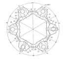
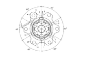
【解決手段】内周面12にトラック溝14を形成した外輪10と、球面状外周面22にトラック溝24を形成した内輪20と、内外輪20,10のトラック溝24,14で形成されるボールトラックに組み込んだn個のボール30と、ボール30を保持するポケット46を有するケージ40とを備え、ケージ40の外周面42の中心Ooと内周面44の中心Oiを、継手中心Oを挟んで軸方向に互いに逆方向に等距離だけオフセットさせた等速自在継手において、外輪10の外径形状をその内径形状に沿った花形に成形し、外輪10のトラック溝14間に位置する外径凹所15に車体取付フランジ18を形成し、かつ、ケージ40あるいは外輪10に、トルク回転時に発生する誘起スラストのn次成分を低減する手段を設ける。
【選択図】図1
Description
12 円筒状内周面
14 トラック溝
15 外径凹所
17 内径部
18 車輪取付フランジ
20 内輪
22 球面状外周面
24 トラック溝
30 トルク伝達ボール
40 ケージ
42 球面状外周面
44 球面状内周面
46 ポケット
47 柱部
O 継手中心
Oo ケージの球面状外周面の中心
Oi ケージの球面状内周面の中心
α0 等ピッチ
L1,L2 外輪の内径部の幅
W1,W2 ケージの柱部の幅
Claims (6)
- 円筒状内周面に軸方向に延びる複数のトラック溝を形成し、外径端部に円周方向に沿って複数の車輪取付フランジが径方向に突設された外輪と、球面状外周面に軸方向に延びる複数のトラック溝を形成した内輪と、前記外輪のトラック溝と前記内輪のトラック溝との対で形成されるボールトラックに一個ずつ組み込んだn個のトルク伝達ボールと、前記トルク伝達ボールを保持するポケットを有するケージとを備え、前記ケージの球面状外周面の中心と球面状内周面の中心を、継手中心を挟んで軸方向に互いに逆方向に等距離だけオフセットさせた等速自在継手において、前記外輪の外径形状をその内径形状に沿った花形に成形し、その外輪のトラック溝間に位置する外径凹所に車体取付フランジを形成し、かつ、前記ケージあるいは外輪に、トルク回転時に発生する誘起スラストのn次成分を低減する手段を設けたことを特徴とする摺動式等速自在継手。
- 前記誘起スラストのn次成分を低減する手段は、前記ボールトラックの円周方向配置を等ピッチにすると共に、前記ケージのポケット間に位置する柱部の幅を少なくとも一箇所以上で不均一とした請求項1に記載の摺動式等速自在継手。
- 前記誘起スラストのn次成分を低減する手段は、ボールトラックの円周方向配置を等ピッチにすると共に、前記外輪のトラック溝間に位置する内径部の幅を少なくとも一箇所以上で不均一にし、かつ、ケージのポケット間に位置する柱部の幅を均一にした請求項1に記載の摺動式等速自在継手。
- 継手の軸線を含む断面で見て、前記ケージの内周面は、内輪の外周面の曲率中心から径方向にずらした位置に曲率中心をもち、内輪の外周面の曲率半径より大きい曲率半径で形成されている請求項1〜3のいずれか一項に記載の摺動式等速自在継手。
- 前記ケージの内周面は、中央部の任意の軸方向寸法にわたる円筒面と、その両側に位置する内輪の外周面と同一曲率半径の部分球面とを結んで形成されている請求項1〜3のいずれか一項に記載の摺動式等速自在継手。
- 前記トルク伝達ボールの個数nが6である請求項1〜5のいずれか一項に記載の摺動式等速自在継手。
Priority Applications (1)
| Application Number | Priority Date | Filing Date | Title |
|---|---|---|---|
| JP2005079750A JP4519686B2 (ja) | 2005-03-18 | 2005-03-18 | 摺動式等速自在継手 |
Applications Claiming Priority (1)
| Application Number | Priority Date | Filing Date | Title |
|---|---|---|---|
| JP2005079750A JP4519686B2 (ja) | 2005-03-18 | 2005-03-18 | 摺動式等速自在継手 |
Publications (2)
| Publication Number | Publication Date |
|---|---|
| JP2006258253A true JP2006258253A (ja) | 2006-09-28 |
| JP4519686B2 JP4519686B2 (ja) | 2010-08-04 |
Family
ID=37097732
Family Applications (1)
| Application Number | Title | Priority Date | Filing Date |
|---|---|---|---|
| JP2005079750A Expired - Fee Related JP4519686B2 (ja) | 2005-03-18 | 2005-03-18 | 摺動式等速自在継手 |
Country Status (1)
| Country | Link |
|---|---|
| JP (1) | JP4519686B2 (ja) |
Cited By (1)
| Publication number | Priority date | Publication date | Assignee | Title |
|---|---|---|---|---|
| WO2010067431A1 (ja) * | 2008-12-10 | 2010-06-17 | トヨタ自動車株式会社 | 車両用プロペラシャフト |
Citations (9)
| Publication number | Priority date | Publication date | Assignee | Title |
|---|---|---|---|---|
| JPS57129925A (en) * | 1981-01-29 | 1982-08-12 | Loehr & Bromkamp Gmbh | Synchronous rotary joint |
| JPS5844932A (ja) * | 1981-09-11 | 1983-03-16 | Toyota Motor Corp | 自在継手の外輪製造方法 |
| JPS61124732A (ja) * | 1984-11-20 | 1986-06-12 | Ntn Toyo Bearing Co Ltd | 等速自在継手 |
| JPS6445536A (en) * | 1987-08-12 | 1989-02-20 | Toyota Motor Corp | Method for assembling synchromesh joint |
| JPH01188719A (ja) * | 1988-01-22 | 1989-07-28 | Ntn Toyo Bearing Co Ltd | ダブルオフセット型等速自在継手 |
| JPH01250619A (ja) * | 1988-03-30 | 1989-10-05 | Ntn Corp | 等速ジョイント |
| JPH02146226U (ja) * | 1989-05-16 | 1990-12-12 | ||
| JPH0814268A (ja) * | 1994-06-29 | 1996-01-16 | Ntn Corp | 摺動式等速ジョイント |
| JPH1073129A (ja) * | 1996-06-28 | 1998-03-17 | Ntn Corp | 摺動型等速自在継手 |
-
2005
- 2005-03-18 JP JP2005079750A patent/JP4519686B2/ja not_active Expired - Fee Related
Patent Citations (9)
| Publication number | Priority date | Publication date | Assignee | Title |
|---|---|---|---|---|
| JPS57129925A (en) * | 1981-01-29 | 1982-08-12 | Loehr & Bromkamp Gmbh | Synchronous rotary joint |
| JPS5844932A (ja) * | 1981-09-11 | 1983-03-16 | Toyota Motor Corp | 自在継手の外輪製造方法 |
| JPS61124732A (ja) * | 1984-11-20 | 1986-06-12 | Ntn Toyo Bearing Co Ltd | 等速自在継手 |
| JPS6445536A (en) * | 1987-08-12 | 1989-02-20 | Toyota Motor Corp | Method for assembling synchromesh joint |
| JPH01188719A (ja) * | 1988-01-22 | 1989-07-28 | Ntn Toyo Bearing Co Ltd | ダブルオフセット型等速自在継手 |
| JPH01250619A (ja) * | 1988-03-30 | 1989-10-05 | Ntn Corp | 等速ジョイント |
| JPH02146226U (ja) * | 1989-05-16 | 1990-12-12 | ||
| JPH0814268A (ja) * | 1994-06-29 | 1996-01-16 | Ntn Corp | 摺動式等速ジョイント |
| JPH1073129A (ja) * | 1996-06-28 | 1998-03-17 | Ntn Corp | 摺動型等速自在継手 |
Cited By (3)
| Publication number | Priority date | Publication date | Assignee | Title |
|---|---|---|---|---|
| WO2010067431A1 (ja) * | 2008-12-10 | 2010-06-17 | トヨタ自動車株式会社 | 車両用プロペラシャフト |
| JP5146538B2 (ja) * | 2008-12-10 | 2013-02-20 | トヨタ自動車株式会社 | 車両用プロペラシャフト |
| US8574084B2 (en) | 2008-12-10 | 2013-11-05 | Toyota Jidosha Kabushiki Kaisha | Vehicle-use propeller shaft |
Also Published As
| Publication number | Publication date |
|---|---|
| JP4519686B2 (ja) | 2010-08-04 |
Similar Documents
| Publication | Publication Date | Title |
|---|---|---|
| US7704150B2 (en) | Sliding type constant velocity universal joint | |
| US7507161B2 (en) | Propshaft with constant velocity joint attachment | |
| EP0950824A2 (en) | Constant velocity joint and rolling bearing unit for wheel | |
| US8894497B2 (en) | Sliding ball type constant velocity joint for vehicle | |
| US8079914B2 (en) | Plunging constant velocity universal joint | |
| US9926985B2 (en) | Sliding ball type constant velocity joint for vehicles | |
| JP4519686B2 (ja) | 摺動式等速自在継手 | |
| KR20050045834A (ko) | 마찰감소 웨브 위치결정구를 가진 등속 죠인트 | |
| JP2008201353A (ja) | インホイールモータ駆動装置 | |
| JP2008008474A (ja) | 固定式等速自在継手 | |
| JP4959848B2 (ja) | 摺動式等速自在継手 | |
| KR102865369B1 (ko) | 휠베어링 조립체 | |
| JP2005207449A (ja) | 等速自在継手 | |
| JP5372364B2 (ja) | トリポード型等速自在継手 | |
| JP2010106892A (ja) | トリポード型等速自在継手 | |
| JP2005207450A (ja) | 摺動式等速自在継手 | |
| JP2018071757A (ja) | トリポード型等速自在継手 | |
| JP2013119868A (ja) | 等速ジョイント | |
| JP2009068682A (ja) | クロスグルーブ型等速自在継手 | |
| JP2006275101A (ja) | トリポード型等速自在継手 | |
| JP2009115222A (ja) | トリポード型等速自在継手 | |
| JP2007170489A (ja) | 等速自在継手 | |
| JP2007211807A (ja) | 固定式等速自在継手 | |
| JP2010105475A (ja) | 車輪用軸受装置 |
Legal Events
| Date | Code | Title | Description |
|---|---|---|---|
| A621 | Written request for application examination |
Free format text: JAPANESE INTERMEDIATE CODE: A621 Effective date: 20080121 |
|
| A131 | Notification of reasons for refusal |
Effective date: 20090908 Free format text: JAPANESE INTERMEDIATE CODE: A131 |
|
| A977 | Report on retrieval |
Effective date: 20090910 Free format text: JAPANESE INTERMEDIATE CODE: A971007 |
|
| A521 | Written amendment |
Effective date: 20091030 Free format text: JAPANESE INTERMEDIATE CODE: A523 |
|
| RD04 | Notification of resignation of power of attorney |
Free format text: JAPANESE INTERMEDIATE CODE: A7424 Effective date: 20091106 |
|
| TRDD | Decision of grant or rejection written | ||
| A01 | Written decision to grant a patent or to grant a registration (utility model) |
Effective date: 20100507 Free format text: JAPANESE INTERMEDIATE CODE: A01 |
|
| A01 | Written decision to grant a patent or to grant a registration (utility model) |
Free format text: JAPANESE INTERMEDIATE CODE: A01 |
|
| A61 | First payment of annual fees (during grant procedure) |
Free format text: JAPANESE INTERMEDIATE CODE: A61 Effective date: 20100519 |
|
| FPAY | Renewal fee payment (prs date is renewal date of database) |
Free format text: PAYMENT UNTIL: 20130528 Year of fee payment: 3 |
|
| R150 | Certificate of patent (=grant) or registration of utility model |
Free format text: JAPANESE INTERMEDIATE CODE: R150 |
|
| LAPS | Cancellation because of no payment of annual fees |