JP2006258902A - Camera shake correction apparatus and portable electronic device with camera using the same - Google Patents
Camera shake correction apparatus and portable electronic device with camera using the same Download PDFInfo
- Publication number
- JP2006258902A JP2006258902A JP2005072969A JP2005072969A JP2006258902A JP 2006258902 A JP2006258902 A JP 2006258902A JP 2005072969 A JP2005072969 A JP 2005072969A JP 2005072969 A JP2005072969 A JP 2005072969A JP 2006258902 A JP2006258902 A JP 2006258902A
- Authority
- JP
- Japan
- Prior art keywords
- shake correction
- camera shake
- camera
- reflecting member
- correction apparatus
- Prior art date
- Legal status (The legal status is an assumption and is not a legal conclusion. Google has not performed a legal analysis and makes no representation as to the accuracy of the status listed.)
- Pending
Links
Images




Landscapes
- Adjustment Of Camera Lenses (AREA)
- Studio Devices (AREA)
Abstract
【課題】簡単な構成でブレ補正を正確に行うことが可能な小型のカメラ用ブレ補正装置およびそれを用いたカメラ付き携帯電子機器を提供する。
【解決手段】 カメラの光学系の光軸を折り曲げる反射部材11と、反射部材11を傾動自在に支持するカメラ用ブレ補正装置ベース16と、カメラ用ブレ補正装置ベース16が反射部材11を支持する支点を中心にして反射部材11を傾動させる駆動部17と、反射部材11の傾動方向に対して反射部材11に予圧を与える弾性部材18と、弾性部材18の変形量を検出するための検出部20を備える。上記検出部20により検出された弾性部材18の変形量に基づいて、制御部が駆動部17を制御することによりカメラのブレに対して反射部材11を傾動させてブレ補正を行う。
【選択図】図7
A compact camera shake correction apparatus capable of accurately performing shake correction with a simple configuration, and a camera-equipped portable electronic device using the same.
A reflection member 11 that bends the optical axis of a camera optical system, a camera shake correction device base 16 that supports the reflection member 11 in a tiltable manner, and a camera shake correction device base 16 that supports the reflection member 11. A driving unit 17 that tilts the reflecting member 11 around the fulcrum, an elastic member 18 that applies a preload to the reflecting member 11 with respect to the tilting direction of the reflecting member 11, and a detecting unit that detects the amount of deformation of the elastic member 18. 20. Based on the deformation amount of the elastic member 18 detected by the detection unit 20, the control unit controls the drive unit 17 to tilt the reflection member 11 with respect to camera shake and perform shake correction.
[Selection] Figure 7
Description
本発明は、カメラ用ブレ補正装置およびそれを用いたカメラ付き携帯電子機器に関し、詳しくは、カメラ付き携帯電子機器の手振れ振動などにより発生する像のぼけを防止するために用いられるカメラ用ブレ補正装置に関するものであり、特に折り曲げ光学系の反射部材を揺動させることによりブレ補正を行う装置に関するものである。 The present invention relates to a camera shake correction apparatus and a camera-equipped portable electronic device using the same, and more particularly to a camera shake correction used to prevent blurring of an image caused by camera shake vibration of the camera-equipped portable electronic device. The present invention relates to an apparatus, and more particularly to an apparatus that performs shake correction by swinging a reflecting member of a bending optical system.
撮影時に手振れ振動などによって撮影機器に振動が与えられた場合に、撮像素子に取り込まれる画像がブレてしまって撮影像が不鮮明になる。これは、暗い場所での撮影や望遠撮影を行うときに特に顕著に現れる。 When vibration is applied to the photographing apparatus due to hand vibration during photographing, an image taken in the image sensor blurs and the photographed image becomes unclear. This is particularly noticeable when shooting in a dark place or telephoto shooting.
このような画像のブレを防ぐ従来のカメラ用ブレ補正装置としては、外部からの振動を検出し、その振動による影響を打ち消すようにカメラ内部の光学系を動的に変位させることによって、撮影像のブレを低減するものが提案されている。このカメラ用ブレ補正装置では、ブレ補正光学系の変位量制御を高精度に行う必要がある。 As a conventional camera shake correction device for preventing such image blurring, a camera image is detected by detecting external vibration and dynamically displacing the optical system inside the camera so as to cancel the influence of the vibration. Some have been proposed to reduce blurring. In this camera shake correction device, it is necessary to control the displacement amount of the shake correction optical system with high accuracy.
従来の折り曲げ光学系における光学系の変位量制御方法としては、角速度検出部により算出されたブレ補正光学系であるミラーの必要チルト角度を算出した後に、ミラーの角度を検出するための位置検出センサを設けたものがある(例えば、特開2004−219930号公報(特許文献1)参照)。 As a method for controlling the amount of displacement of an optical system in a conventional bending optical system, a position detection sensor for detecting a mirror angle after calculating a necessary tilt angle of a mirror, which is a shake correction optical system calculated by an angular velocity detection unit. (For example, refer to JP 2004-219930 A (Patent Document 1)).
また、ミラーの位置を撮像素子によって検出することにより、圧電素子に印加する電圧にフィードバックする方法などが挙げられている。 Further, there is a method of feeding back the voltage applied to the piezoelectric element by detecting the position of the mirror with an imaging element.
さらに、圧電素子が印加電圧に比例する特徴を利用して、センサを設けないで駆動源に用いている圧電素子の電圧によりミラーの角度を検出する方法も提案されている。 Furthermore, a method has been proposed in which the angle of the mirror is detected based on the voltage of the piezoelectric element used as a drive source without providing a sensor, utilizing the feature that the piezoelectric element is proportional to the applied voltage.
しかし、上述した従来技術には、次のような問題がある。 However, the above-described conventional technology has the following problems.
上記折り曲げ光学系における光学系の変位量制御方法においては、ミラーの角度を検出するために、PSD(Position Sensitive Device:位置検出素子)、PI(フォトインタラプタ)等のセンサを別に用意する場合、そのセンサを配置する場所が別途必要となり、これはカメラ用ブレ補正装置を携帯電話等の小型の携帯電子機器に内蔵するような用途を考えた場合、センサを取り付ける障害となる。 In the above-described optical system displacement control method in the bending optical system, in order to separately detect sensors such as PSD (Position Sensitive Device) and PI (Photo Interrupter) in order to detect the angle of the mirror, A place where the sensor is arranged is separately required. This is an obstacle to mounting the sensor when considering an application in which the camera shake correction apparatus is built in a small portable electronic device such as a mobile phone.
また、上記ミラーの位置を撮像素子によって検出する方法において、動きベクトル抽出を行うには動画フレーム間ごとの特徴点の軌跡を算出する必要があり、一枚の静止画の撮影を行うときに露光中にミラーの位置がずれると、動きベクトルの算出ができず、正確な補正を行うことができない。 In addition, in the method of detecting the mirror position by the image sensor, it is necessary to calculate the trajectory of the feature point for each moving image frame in order to extract the motion vector, and the exposure is performed when shooting one still image. If the position of the mirror is shifted, the motion vector cannot be calculated, and accurate correction cannot be performed.
また、上記駆動源に用いている圧電素子の電圧を検出によりミラーの角度を検出する方法についても、一般的に圧電素子にはヒステリシスが存在し、電圧値に対する変位量が1対1に対応しないためにミラーの角度が正確に得られない。特に、電圧に対する変位量の大きな圧電材料(圧電定数の大きな材料)を用いた場合は、ヒステリシスが約10%〜20%と大きくなる一方、ヒステリシスが3%以下の圧電材料を駆動源に用いた場合は、電圧に対する変位量が小さいため、必要な変位を得るのにヒステリシスの大きな圧電材料を用いる場合よりも2倍程度高い電圧が必要となるから、携帯機器に用いるときの障害となる。
そこで、本発明の目的は、簡単な構成でブレ補正を正確に行うことが可能な小型のカメラ用ブレ補正装置およびそれを用いたカメラ付き携帯電子機器を提供することにある。 SUMMARY OF THE INVENTION Accordingly, an object of the present invention is to provide a small camera shake correction apparatus capable of performing shake correction accurately with a simple configuration and a portable electronic device with a camera using the same.
上記目的を達成するため、本発明のカメラ用ブレ補正装置は、
カメラの光学系の光軸を折り曲げる反射部材と、
上記反射部材を傾動自在に支持する支持部材と、
上記支持部材が上記反射部材を支持する支点を中心にして上記反射部材を傾動させる駆動部と、
上記反射部材の傾動方向に対して上記反射部材に予圧を与える弾性部材と、
上記弾性部材の変形量を検出するための検出部と、
上記検出部により検出された上記弾性部材の変形量に基づいて、上記駆動部を制御することにより上記カメラのブレに対して上記反射部材を傾動させてブレ補正を行う制御部と
を備えたことを特徴とする。
In order to achieve the above object, a camera shake correction apparatus according to the present invention comprises:
A reflective member that bends the optical axis of the optical system of the camera;
A support member that tiltably supports the reflection member;
A drive unit that tilts the reflecting member around a fulcrum where the supporting member supports the reflecting member; and
An elastic member for applying a preload to the reflecting member with respect to the tilting direction of the reflecting member;
A detection unit for detecting the deformation amount of the elastic member;
A control unit that performs blur correction by tilting the reflection member with respect to camera shake by controlling the drive unit based on the deformation amount of the elastic member detected by the detection unit. It is characterized by.
上記構成のカメラ用ブレ補正装置によれば、上記反射部材の傾動方向に対して反射部材に予圧を与えている弾性部材の変形量(反射部材の傾動量に相当)を検出部により検出することによって、部材の変形量を知る手段として例えば薄くて小さい圧電素子を利用できるため、反射部材の傾動量を検出するために特別な場所を設ける必要がなく、省スペース化を図ることができる。したがって、簡単な構成でブレ補正を正確に行うことが可能な小型のカメラ用ブレ補正装置を実現できる。 According to the camera shake correction apparatus having the above-described configuration, the detection unit detects the amount of deformation of the elastic member that applies preload to the reflecting member with respect to the tilting direction of the reflecting member (corresponding to the tilting amount of the reflecting member). Therefore, for example, a thin and small piezoelectric element can be used as a means for knowing the deformation amount of the member, so that it is not necessary to provide a special place for detecting the tilting amount of the reflecting member, and space can be saved. Therefore, it is possible to realize a small camera shake correction apparatus that can accurately perform the shake correction with a simple configuration.
また、一実施形態のカメラ用ブレ補正装置は、上記弾性部材が上記反射部材に予圧を与える予圧位置と、上記駆動部が上記反射部材に変位を与える押圧位置と、上記支持部材が上記反射部材を支持する支点の位置が、上記反射部材の反射面に対して略直角な同一平面上に配置されていることを特徴とする。 In one embodiment, the camera shake correction apparatus includes a preload position where the elastic member applies preload to the reflecting member, a pressing position where the driving unit applies displacement to the reflecting member, and the support member includes the reflecting member. The position of the fulcrum that supports is arranged on the same plane substantially perpendicular to the reflecting surface of the reflecting member.
上記実施形態のカメラ用ブレ補正装置によれば、弾性部材が反射部材に予圧を与える予圧位置と、駆動部が反射部材に変位を与える押圧位置と、支持部材が反射部材を支持する支点の位置が、反射部材の反射面に対して略直角な同一平面上に配置されているため、この平面に沿った反射部材の傾動が他の面に沿った方向の傾動の影響を受けずに傾動量に相当する弾性部材の変形量を検出することができる。 According to the camera shake correction apparatus of the above-described embodiment, the preload position where the elastic member preloads the reflecting member, the pressing position where the driving unit applies displacement to the reflecting member, and the position of the fulcrum where the supporting member supports the reflecting member. Are arranged on the same plane substantially perpendicular to the reflecting surface of the reflecting member, so that the tilting of the reflecting member along this plane is not affected by the tilting in the direction along the other surface, and the amount of tilting is not affected. The amount of deformation of the elastic member corresponding to can be detected.
また、一実施形態のカメラ用ブレ補正装置は、上記検出部が圧電素子であることを特徴とする。 In one embodiment of the camera shake correction apparatus, the detection unit is a piezoelectric element.
上記実施形態のカメラ用ブレ補正装置によれば、弾性部材の変形量の検出に圧電素子を用いることによって、装置の薄型化を図ることができると共に、構成が簡単になる。 According to the camera shake correction apparatus of the above embodiment, the piezoelectric element is used for detecting the deformation amount of the elastic member, whereby the apparatus can be thinned and the configuration is simplified.
また、一実施形態のカメラ用ブレ補正装置は、上記反射部材の反射面に対して略直角で互いに直交する2つの平面に沿って、上記駆動部により上記反射部材が傾動することを特徴とする。 The camera shake correction apparatus according to an embodiment is characterized in that the reflecting member is tilted by the driving unit along two planes that are substantially perpendicular to the reflecting surface of the reflecting member and orthogonal to each other. .
上記実施形態のカメラ用ブレ補正装置によれば、反射部材の反射面に対して略直角で互いに直交する2つの平面に沿って、駆動部により反射部材を傾動させることによって、カメラのヨーイング方向とピッチング方向の振れを正確に補正することができる。 According to the camera shake correction apparatus of the above embodiment, the drive member tilts the reflection member along two planes that are substantially perpendicular to the reflection surface of the reflection member and perpendicular to each other, thereby causing the yawing direction of the camera to be The shake in the pitching direction can be accurately corrected.
また、この発明のカメラ付き携帯電子機器は、上記のいずれか1つのカメラ用ブレ補正装置を備えたことを特徴とする。 According to another aspect of the present invention, there is provided a camera-equipped mobile electronic device including any one of the camera shake correction apparatuses described above.
上記実施形態のカメラ付き携帯電子機器によれば、上記カメラ用ブレ補正装置を用いることによって、正確なブレ補正ができると共に、小型化が図れる。 According to the camera-equipped mobile electronic device of the embodiment, by using the camera shake correction apparatus, accurate shake correction can be performed and the size can be reduced.
以上より明らかなように、本発明のカメラ用ブレ補正装置によれば、簡単な構成でブレ補正を正確に行うことが可能な小型のカメラ用ブレ補正装置を実現することができる。 As is clear from the above, according to the camera shake correction apparatus of the present invention, it is possible to realize a small camera shake correction apparatus capable of performing shake correction accurately with a simple configuration.
また、本発明のカメラ付き携帯電子機器によれば、上記カメラ用ブレ補正装置を用いることにより、正確なブレ補正ができる小型のカメラ付き携帯電子機器を実現することができる。 In addition, according to the camera-equipped mobile electronic device of the present invention, a small camera-equipped mobile electronic device capable of accurate blur correction can be realized by using the camera shake correction device.
以下、本発明のカメラ用ブレ補正装置およびそれを用いたカメラ付き携帯電子機器を図示の実施の形態により詳細に説明する。なお、本発明は以下の実施形態に限定されるものではない。 DETAILED DESCRIPTION OF THE PREFERRED EMBODIMENTS Hereinafter, a camera shake correction apparatus and a camera-equipped portable electronic device using the same according to the present invention will be described in detail with reference to the illustrated embodiments. In addition, this invention is not limited to the following embodiment.
図1乃至図3を用いて、本発明のカメラ用ブレ補正装置を用いたカメラ付き携帯電子機器の一例としてのカメラ付き携帯電話の説明を行う。 A camera-equipped mobile phone as an example of a camera-equipped mobile electronic device using the camera shake correction apparatus of the present invention will be described with reference to FIGS.
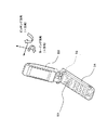
図1は本発明のカメラ用ブレ補正装置を用いたカメラ付き携帯電話200の要部ブロック図である。また、図2は本発明のカメラ用ブレ補正装置を内蔵したカメラ付き携帯電話の第1撮影形態を示す斜視図であり、図3は同じカメラ付き携帯電話における第2の撮影形態を示す斜視図である。
FIG. 1 is a principal block diagram of a camera-equipped
図1において、101は角速度センサ(ジャイロセンサ等)からなる第1角速度検出センサ、102は角速度センサからなる第2角速度検出センサ、103は第1,第2角速度検出センサ101,102からの角速度信号のDC成分を除去するHPF(ハイパスフィルタ)、104は上記HPF103からの角速度信号を増幅するAMP(アンプリファイアー)、105は上記AMP104からの角速度信号を積分して角度信号を求める積分回路、120は上記積分回路105からの角度信号を受けて制御信号を出力する制御部、106は上記制御部120からの制御信号に基づいて駆動信号を出力する駆動回路、17は上記駆動回路106からの駆動信号により駆動される駆動部、11は上記駆動部17により傾動させる反射部材、20は反射部材11の揺動量を検出するための検出部である。また、30はカメラユニット(図示せず)の光学系、40は上記光学系30を介して被写体の像が写される撮像素子であるCCD(チャージ・カップルド・デバイス:電荷結合素子)、107は上記CCD40からのアナログ画像信号をA/D(アナログ/デジタル)変換するA/Dコンバータ、108は上記A/Dコンバータ107からのデジタル信号を処理するデジタル信号処理部、109は上記デジタル信号処理部108により信号処理された画像を保存するメモリである。また、50は第1撮影操作部、51は第2撮影操作部である。
In FIG. 1, 101 is a first angular velocity detection sensor comprising an angular velocity sensor (such as a gyro sensor), 102 is a second angular velocity detection sensor comprising an angular velocity sensor, and 103 is an angular velocity signal from the first and second angular
上記構成のカメラ付き携帯電話200において、カメラ用ブレ補正装置100は、積分回路105からの角度信号の変化に応じて駆動回路106から出力された駆動信号により駆動部17を駆動し、反射部材11を光軸に対して直交する2軸を中心に揺動させる。このとき、検出部20の検出結果に基づいて適切な制御量を制御部120により算出し、制御部120から制御量を駆動回路106にフィードバックすることにより、カメラ付き携帯電話200が振動することによる画像の揺れを低減することが可能となる。
In the camera-equipped
その後、図2の第1撮影操作部50もしくは図3に示す第2撮影操作部51が押されたことを検出して、反射部材11,光学系30を通過して、CCD40上に結像されたアナログ画像信号をA/Dコンバータ107により、デジタル信号に変換し、デジタル信号処理部108により画像圧縮などの所定の信号処理を行った後に、メモリ109に画像が保存される。
After that, it is detected that the first
続いて、図2を用いて、撮影機器蓋部53と撮影機器本体54を開けた状態で撮影を行う第1撮影形態の説明を行う。ここでは、カメラユニット52は撮影機器本体54に取り付けられており、第1撮影操作部50を押すことにより先に説明したように画像の撮影が行われる。また、このときのピッチング方向のブレ振動は第1角速度検出センサ101(図1に示す)によって検出され、ヨーイング方向のブレ振動は第2角速度検出センサ102(図1に示す)により検出される。一方、図3に示す撮影機器蓋部53と撮影機器本体54を閉じた状態で撮影する第2撮影形態では、第2撮影操作部51が押されることにより同様に画像の撮影が行われ、このときのピッチング方向のブレ振動は第2角速度検出センサ102により検出され、ヨーイング方向のブレ振動は第1角速度検出センサ101により検出される。
Next, a first photographing mode in which photographing is performed with the photographing
次に、図4,図5を用いて本発明のカメラユニットの構成について説明を行う。図4は図2、図3に内蔵されているカメラユニット52の斜視図を示しており、CCD40は下側に配置されている。このカメラユニット52の内部には、図示しないレンズ間隔を変更することにより変倍をおこなうズーム機構、パッシブ方式のオートフォーカス機構、シャッター等が内蔵されており、それら機構はすべてカメラユニット52に固定されている。
Next, the configuration of the camera unit of the present invention will be described with reference to FIGS. FIG. 4 is a perspective view of the
また、図5は図4に示すカメラユニット52の内部部品の説明を行うための要部の斜視図である。ここで矢印R4方向から入射した光線は、反射部材11により直角に折り曲げられ、光学系30を通過して撮像素子であるCCD40に集光されて像が結ばれる。以下の画像処理方法については先ほど説明したのと同一であるので省略する。
FIG. 5 is a perspective view of the main part for explaining the internal components of the
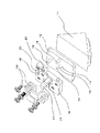
続いて、反射部材11を揺動するカメラ用ブレ補正装置100についての説明を図6乃至図9を用いて説明する。ここで図6は本カメラ用ブレ補正装置100の要部の斜視図であり、図7は図6の分解斜視図である。
Next, the camera
図6, 図7において、反射部材ベース12は反射部材11の背面に接着固定されている。また、中心軸13(図7のみに示す)は、一端が反射部材ベース12に固定され、他端が支持部材の一例としてのカメラ用ブレ補正装置ベース16に固定された弾性材である。上記中心軸13は、反射部材ベース12の傾動に伴ってたわみ変形する。そして、反射部材ベース12に変位を与える駆動部17としては、積層型の圧電素子が用いられており、圧電素子に電圧を印加されると、図6の矢印R6方向である反射部材11の裏面に垂直な方向に変位する。この駆動部17は、一端が反射部材ベース12に設けられている押圧部突起14(図7に示す)と接触しており、他端は駆動部固定部材19と接着固定されている。さらに駆動部固定部材19は、カメラ用ブレ補正装置ベース16に対してネジ固定されており、このカメラ用ブレ補正装置ベース16はカメラユニット52(図4に示す)に固定されている。また、予圧部突起15は反射部材ベース12に取り付けられており、弾性部材18と接触することにより駆動部17と押圧部突起14の接触部分に予圧を与えている。この弾性部材18は板バネ形状を成しており、弾性部材18の一端は予圧部突起15に対して予圧を与えており、弾性部材18の他端はカメラ用ブレ補正装置ベース16に固定されている。
6 and 7, the reflecting
そして、この弾性部材18の表面に弾性部材の変形量を検出するための検出部20が設けられており、その検出部20として圧電素子が接着されている。この圧電素子には両面に電極が設けられており、歪を受けることにより素子両端の電圧が変化する。この圧電素子の両端電圧を検出することで、反射部材11のチルト量と比例関係を有する弾性部材18の変形量がわかる。こうして得られた弾性部材18の変形量に基づいて、反射部材11のチルト量を検出できる。
A detecting
この圧電素子材料としては、水晶などのヒステリシスが小さく温度変化による圧電定数の変化の少ない材料であるのが望ましい。 The piezoelectric element material is desirably a material such as quartz that has a small hysteresis and a small change in piezoelectric constant due to a temperature change.
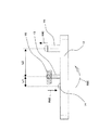
続いて、図8,図9を用いて、反射部材11が固定された反射部材ベース12の中心軸13、押圧部突起14、予圧部突起15の配置関係について説明を行う。図8は反射部材ベース12を上から見たときの中心軸13、押圧部突起14、予圧部突起15の配置関係を説明する図であり、図9は図8の矢印R8方向から見たときの矢視図である。
Next, the positional relationship among the
ここで、図8,図9に示すように、反射部材ベース12は、その略中央部に円柱形状の中心軸13が立設されており、その中心軸13の中心位置23と、押圧部突起14と駆動部17が接触している2箇所の押圧位置21が、それぞれ直角2等辺3角形の頂角を形成するように配置されている。また、各押圧位置21の中心位置23に対して反対側に夫々予圧位置22を配置している。
Here, as shown in FIGS. 8 and 9, the reflecting
また、駆動部17が接触している押圧部突起14の部分は球面となっており、押圧部突起14と駆動部17とは点接触をしている。そのため、一方の押圧部突起14が変位したときに、他方の押圧部突起14が固定されておらず、点で接触しているだけなので、2つの傾動方向の夫々がお互いに他方の運動を阻害することがない。
Further, the portion of the
さらに、押圧部突起14と中心軸13の中心位置23を結ぶ延長上に予圧部突起15が設けられている。このため、一方の押圧部突起14が変位したときも、中心軸13との延長線上に無い他方の予圧部突起15の変位には影響しない。
Further, a
また、予圧部突起15と弾性部材18(図6,図7に示す)が接触して、弾性部材18を変形させることで、予圧部突起15に図9に示す下向き方向の力を与えることにより、押圧部突起14と駆動部17の接触が常に維持できるようになっている。この予圧部突起15についても弾性部材18との接触する箇所は球面となっており、弾性部材18とは点接触をしているため、押圧部突起14の変位や他方の予圧部突起15の変位による影響を受けない。また、反射部材ベース12のチルト量が5〜10分と極めて小さいことから、押圧部突起14と中心軸13までの距離L1とし、中心軸13から予圧部突起15までの距離L2とすると、予圧部突起15の変位量は、押圧部突起14の変位量のL2/L1倍になる。この比(L2/L1)が大きくなるほど、図示しない反射部材のチルト量の検出感度が上がるために、なるべく大きくしたほうが好ましい。本実施形態では、予圧部突起15の変位量を押圧部突起14の変位量の約3倍にしている。
Further, the
ここで、図6に示す圧電素子からなる駆動部17により図9に示す押圧部突起14に矢印R9B方向に変位を与えられたとき、中心軸13が撓んで傾くことにより、反射部材11が中心軸13を支点として矢印R9Cの方向に傾動する。
Here, when the
ここで、中心軸13の材質としては、押圧部突起14が矢印R9Bの方向に変位されたときに中心軸13が長手方向に伸びてしまうと、図示しない反射部材のチルト量が小さくなってしまうか、最悪の場合は傾動しなくなるため、引っ張り剛性の高い材料である金属、もしくは樹脂材料が望ましい。
Here, as the material of the
以上のような手法を用いることにより、予圧部突起15の変位(矢印R9Dの方向)を検出部20により検出することで、反射部材11のチルト量を正確に検出することが可能となる。
By using the above method, the tilt amount of the reflecting
上記構成のカメラ用ブレ補正装置によれば、反射部材11に予圧を与えている弾性部材18の変形量(反射部材11の傾動量に相当)を検出する検出部20を設けることによって、部材の変形量を知る手段として薄くて小さい圧電素子等の検出素子を利用できるため、反射部材11の傾動量を検出するために特別な場所を設ける必要がなく、省スペース化を図ることができる。したがって、簡単な構成でブレ補正を正確に行うことが可能な小型のカメラ用ブレ補正装置を実現することができる。
According to the camera shake correction apparatus having the above-described configuration, by providing the
また、上記弾性部材18が反射部材11に予圧を与える予圧位置22と、駆動部17が反射部材11に変位を与える押圧位置21と、支持部材(カメラ用ブレ補正装置ベース16)が反射部材11を支持する支点の位置(中心軸13)が、反射部材11の反射面に対して略直角な同一平面上に配置されているため、他の方向への傾動運動の影響を受けずに傾動量に相当する弾性部材18の変形量を検出することができる。
The
また、上記弾性部材18の変形量を検出する検出部20に圧電素子を用いることによって、装置の薄型化を図ることができると共に、構成を簡単化することができる。
Further, by using a piezoelectric element for the
また、反射部材11の反射面に対して略直角で互いに直交する2つの平面に沿って、駆動部17により反射部材11を傾動させることによって、カメラのヨーイング方向とピッチング方向の振れを正確に補正することができる。
In addition, the
また、この発明のカメラ付き携帯電子機器は、上記カメラ用ブレ補正装置を用いることによって、正確なブレ補正ができると共に、小型化が図れる。 In addition, the camera-equipped mobile electronic device according to the present invention can perform accurate shake correction and can be miniaturized by using the camera shake correction device.
上記実施の形態では、カメラ用ブレ補正装置を用いたカメラ付き携帯電話について説明したが、本発明のカメラ用ブレ補正装置は、デジタルカメラやPDA(Personal Digital Assistant:パーソナル・デジタル・アシスタント)等の他のカメラ付き携帯電子機器に適用してもよい。 In the above embodiment, the camera-equipped mobile phone using the camera shake correction apparatus has been described. However, the camera shake correction apparatus of the present invention is a digital camera, a PDA (Personal Digital Assistant), or the like. You may apply to another portable electronic device with a camera.
本発明のカメラ用ブレ補正装置およびそれを用いたカメラ付き携帯電子機器は、全般に適用することが可能であり、特に携帯用途に適した小型の撮影機器にブレ補正機構を内蔵することが可能となる。 The camera shake correction apparatus of the present invention and a portable electronic device with a camera using the same can be applied in general, and a shake correction mechanism can be incorporated in a small photographic device particularly suitable for portable use. It becomes.
11…反射部材
12…反射部材ベース
13…中心軸
14…押圧部突起
15…予圧部突起
16…カメラ用ブレ補正装置ベース
17…駆動部
18…弾性部材
19…駆動部固定部材
20…検出部
21…押圧位置
22…予圧位置
23…中心位置
30…光学系
40…CCD
50…第1撮影操作部
51…第2撮影操作部
52…カメラユニット
53…撮影機器蓋部
54…撮影機器本体
70…検出部
100…カメラ用ブレ補正装置
101…第1角速度検出部
102…第2角速度検出部
103…HPF
104…AMP
105…積分器
106…駆動回路
107…ADコンバータ
108…デジタル信号処理部
109…メモリ
120…制御部
200…カメラ付き携帯電話
DESCRIPTION OF
DESCRIPTION OF
104 ... AMP
DESCRIPTION OF
Claims (5)
上記反射部材を傾動自在に支持する支持部材と、
上記支持部材が上記反射部材を支持する支点を中心にして上記反射部材を傾動させる駆動部と、
上記反射部材の傾動方向に対して上記反射部材に予圧を与える弾性部材と、
上記弾性部材の変形量を検出するための検出部と、
上記検出部により検出された上記弾性部材の変形量に基づいて、上記駆動部を制御することにより上記カメラのブレに対して上記反射部材を傾動させてブレ補正を行う制御部と
を備えたことを特徴とするカメラ用ブレ補正装置。 A reflective member that bends the optical axis of the optical system of the camera;
A support member that tiltably supports the reflection member;
A drive unit that tilts the reflecting member around a fulcrum where the supporting member supports the reflecting member; and
An elastic member for applying a preload to the reflecting member with respect to the tilting direction of the reflecting member;
A detection unit for detecting the deformation amount of the elastic member;
A control unit that performs blur correction by tilting the reflection member with respect to camera shake by controlling the drive unit based on the deformation amount of the elastic member detected by the detection unit. A camera shake correction device characterized by the above.
上記弾性部材が上記反射部材に予圧を与える予圧位置と、上記駆動部が上記反射部材に変位を与える押圧位置と、上記支持部材が上記反射部材を支持する支点の位置が、上記反射部材の反射面に対して略直角な同一平面上に配置されていることを特徴とするカメラ用ブレ補正装置。 The camera shake correction apparatus according to claim 1,
The preload position where the elastic member applies preload to the reflecting member, the pressing position where the driving unit applies displacement to the reflecting member, and the position of the fulcrum where the supporting member supports the reflecting member are reflected by the reflecting member. A camera shake correction device, wherein the camera shake correction device is disposed on the same plane substantially perpendicular to the surface.
上記検出部が圧電素子であることを特徴とするカメラ用ブレ補正装置。 The camera shake correction apparatus according to claim 1 or 2,
A camera shake correction apparatus, wherein the detection unit is a piezoelectric element.
上記反射部材の反射面に対して略直角で互いに直交する2つの平面に沿って、上記駆動部により上記反射部材が傾動することを特徴とするカメラ用ブレ補正装置。 The camera shake correction apparatus according to any one of claims 1 to 3,
The camera shake correction apparatus according to claim 1, wherein the driving member tilts the reflecting member along two planes substantially perpendicular to the reflecting surface of the reflecting member and perpendicular to each other.
Priority Applications (1)
| Application Number | Priority Date | Filing Date | Title |
|---|---|---|---|
| JP2005072969A JP2006258902A (en) | 2005-03-15 | 2005-03-15 | Camera shake correction apparatus and portable electronic device with camera using the same |
Applications Claiming Priority (1)
| Application Number | Priority Date | Filing Date | Title |
|---|---|---|---|
| JP2005072969A JP2006258902A (en) | 2005-03-15 | 2005-03-15 | Camera shake correction apparatus and portable electronic device with camera using the same |
Publications (1)
| Publication Number | Publication Date |
|---|---|
| JP2006258902A true JP2006258902A (en) | 2006-09-28 |
Family
ID=37098279
Family Applications (1)
| Application Number | Title | Priority Date | Filing Date |
|---|---|---|---|
| JP2005072969A Pending JP2006258902A (en) | 2005-03-15 | 2005-03-15 | Camera shake correction apparatus and portable electronic device with camera using the same |
Country Status (1)
| Country | Link |
|---|---|
| JP (1) | JP2006258902A (en) |
Cited By (1)
| Publication number | Priority date | Publication date | Assignee | Title |
|---|---|---|---|---|
| JP2008191615A (en) * | 2007-02-08 | 2008-08-21 | Casio Comput Co Ltd | Image stabilizer |
Citations (3)
| Publication number | Priority date | Publication date | Assignee | Title |
|---|---|---|---|---|
| JPH04211230A (en) * | 1989-10-20 | 1992-08-03 | Fuji Photo Film Co Ltd | Compensator for camera shake by hand |
| JPH04219709A (en) * | 1990-12-20 | 1992-08-10 | Canon Inc | Lens shifting device |
| JPH11344740A (en) * | 1998-06-02 | 1999-12-14 | Tochigi Nikon:Kk | Blur correction device and optical device |
-
2005
- 2005-03-15 JP JP2005072969A patent/JP2006258902A/en active Pending
Patent Citations (3)
| Publication number | Priority date | Publication date | Assignee | Title |
|---|---|---|---|---|
| JPH04211230A (en) * | 1989-10-20 | 1992-08-03 | Fuji Photo Film Co Ltd | Compensator for camera shake by hand |
| JPH04219709A (en) * | 1990-12-20 | 1992-08-10 | Canon Inc | Lens shifting device |
| JPH11344740A (en) * | 1998-06-02 | 1999-12-14 | Tochigi Nikon:Kk | Blur correction device and optical device |
Cited By (1)
| Publication number | Priority date | Publication date | Assignee | Title |
|---|---|---|---|---|
| JP2008191615A (en) * | 2007-02-08 | 2008-08-21 | Casio Comput Co Ltd | Image stabilizer |
Similar Documents
| Publication | Publication Date | Title |
|---|---|---|
| TWI414815B (en) | Camera shake vibration correction device | |
| JP3861815B2 (en) | Camera with image stabilization function | |
| US6631042B2 (en) | Lens barrel having image shake correcting function and optical device having same | |
| CN101762939B (en) | Image stabilizer for optical instrument | |
| CN100510931C (en) | Image capture device | |
| JP2703105B2 (en) | Image stabilization device | |
| JP4844177B2 (en) | Blur correction device and camera | |
| US20060133786A1 (en) | Driving mechanism, driving system, anti-shake unit, and image sensing apparatus | |
| JP2007047547A (en) | Electronic imaging device with camera shake correction function and portable electronic device with camera | |
| CN1979254A (en) | Image stabilizer, lens device and imager apparatus | |
| EP1916566B1 (en) | Image blurring correction unit, image blurring correction apparatus, and imaging apparatus | |
| JP4751695B2 (en) | Imaging device with image stabilization function | |
| JPWO2014069251A1 (en) | The camera module | |
| CN104136986A (en) | Camera drive device | |
| JP2003172961A (en) | Image stabilization device and photographing device | |
| JP2007041455A (en) | Image blur correction device for optical device | |
| JP2006166202A (en) | Optical device and digital camera | |
| CN101688976A (en) | A device for providing stabilized images in a hand held camera | |
| JP2008035308A (en) | Electronic camera and lens unit | |
| US20070047936A1 (en) | Image sensing apparatus | |
| JP4728086B2 (en) | Imaging device with image stabilization function | |
| JP5397730B2 (en) | Electronic camera | |
| JP2006300997A (en) | Image pickup apparatus having image blur prevention function | |
| JP4755477B2 (en) | Imaging device with image stabilization function | |
| JP2001066655A (en) | Photographic device with anti-vibration function |
Legal Events
| Date | Code | Title | Description |
|---|---|---|---|
| A621 | Written request for application examination |
Free format text: JAPANESE INTERMEDIATE CODE: A621 Effective date: 20070302 |
|
| A977 | Report on retrieval |
Free format text: JAPANESE INTERMEDIATE CODE: A971007 Effective date: 20091106 |
|
| A131 | Notification of reasons for refusal |
Free format text: JAPANESE INTERMEDIATE CODE: A131 Effective date: 20091110 |
|
| A02 | Decision of refusal |
Free format text: JAPANESE INTERMEDIATE CODE: A02 Effective date: 20100309 |