JP2006276830A - Image forming method and image forming apparatus - Google Patents
Image forming method and image forming apparatus Download PDFInfo
- Publication number
- JP2006276830A JP2006276830A JP2005334117A JP2005334117A JP2006276830A JP 2006276830 A JP2006276830 A JP 2006276830A JP 2005334117 A JP2005334117 A JP 2005334117A JP 2005334117 A JP2005334117 A JP 2005334117A JP 2006276830 A JP2006276830 A JP 2006276830A
- Authority
- JP
- Japan
- Prior art keywords
- image forming
- bias
- image
- toner
- color
- Prior art date
- Legal status (The legal status is an assumption and is not a legal conclusion. Google has not performed a legal analysis and makes no representation as to the accuracy of the status listed.)
- Pending
Links
Images


Classifications
-
- G—PHYSICS
- G03—PHOTOGRAPHY; CINEMATOGRAPHY; ANALOGOUS TECHNIQUES USING WAVES OTHER THAN OPTICAL WAVES; ELECTROGRAPHY; HOLOGRAPHY
- G03G—ELECTROGRAPHY; ELECTROPHOTOGRAPHY; MAGNETOGRAPHY
- G03G21/00—Arrangements not provided for by groups G03G13/00 - G03G19/00, e.g. cleaning, elimination of residual charge
- G03G21/0005—Arrangements not provided for by groups G03G13/00 - G03G19/00, e.g. cleaning, elimination of residual charge for removing solid developer or debris from the electrographic recording medium
- G03G21/0035—Arrangements not provided for by groups G03G13/00 - G03G19/00, e.g. cleaning, elimination of residual charge for removing solid developer or debris from the electrographic recording medium using a brush; Details of cleaning brushes, e.g. fibre density
-
- G—PHYSICS
- G03—PHOTOGRAPHY; CINEMATOGRAPHY; ANALOGOUS TECHNIQUES USING WAVES OTHER THAN OPTICAL WAVES; ELECTROGRAPHY; HOLOGRAPHY
- G03G—ELECTROGRAPHY; ELECTROPHOTOGRAPHY; MAGNETOGRAPHY
- G03G21/00—Arrangements not provided for by groups G03G13/00 - G03G19/00, e.g. cleaning, elimination of residual charge
- G03G21/0005—Arrangements not provided for by groups G03G13/00 - G03G19/00, e.g. cleaning, elimination of residual charge for removing solid developer or debris from the electrographic recording medium
- G03G21/0047—Arrangements not provided for by groups G03G13/00 - G03G19/00, e.g. cleaning, elimination of residual charge for removing solid developer or debris from the electrographic recording medium using electrostatic or magnetic means; Details thereof, e.g. magnetic pole arrangement of magnetic devices
-
- G—PHYSICS
- G03—PHOTOGRAPHY; CINEMATOGRAPHY; ANALOGOUS TECHNIQUES USING WAVES OTHER THAN OPTICAL WAVES; ELECTROGRAPHY; HOLOGRAPHY
- G03G—ELECTROGRAPHY; ELECTROPHOTOGRAPHY; MAGNETOGRAPHY
- G03G2221/00—Processes not provided for by group G03G2215/00, e.g. cleaning or residual charge elimination
- G03G2221/0005—Cleaning of residual toner
Landscapes
- Physics & Mathematics (AREA)
- General Physics & Mathematics (AREA)
- Color Electrophotography (AREA)
- Cleaning In Electrography (AREA)
- Dry Development In Electrophotography (AREA)
Abstract
【課題】 複数の画像形成ユニットを有するタンデム方式のクリーナレスの画像形成装置にて、撹乱部材に捕集した残留トナーを原因とする像担持体のフィルミングの発生を防止して像担持体の長寿命化を図る。
【解決手段】 複数の画像形成ユニットを有するタンデム方式の画像形成装置にて任意の画像形成ユニットが画像形成操作中に、画像形成操作に寄与しない画像形成ユニットの撹乱部材のバイアスを現像時の第1のバイアスから第2のバイアスに変更して、撹乱部材にたまっているトナーを早いタイミングで吐き出して現像器で回収する。第1のバイアスから第2のバイアスへの変更を所定の速度として、撹乱部材にたまっているトナーを徐々に吐き出す。
【選択図】図4PROBLEM TO BE SOLVED: To prevent filming of an image carrier caused by residual toner collected on a disturbance member in a tandem type cleanerless image forming apparatus having a plurality of image forming units. Longer life.
In a tandem-type image forming apparatus having a plurality of image forming units, when any image forming unit performs an image forming operation, a bias of a disturbing member of the image forming unit that does not contribute to the image forming operation is corrected during development. By changing from the first bias to the second bias, the toner accumulated in the disturbing member is discharged at an early timing and collected by the developing device. The change from the first bias to the second bias is set at a predetermined speed, and the toner accumulated in the disturbance member is gradually discharged.
[Selection] Figure 4
Description
本発明は画像形成装置に係り、特転写終了後の感光体ドラム上の残留トナーをクリーニングする画像形成方法及び画像形成装置に関する。 The present invention relates to an image forming apparatus, and more particularly to an image forming method and an image forming apparatus for cleaning residual toner on a photosensitive drum after completion of special transfer.
複写機やプリンタ等のカラーの画像形成装置においては、複数の感光体ドラムをタンデムに配列してなる画像形成装置がある。この様なタンデム方式の画像形成装置として、カラー用の感光体ドラムを有する複数のカラー画像形成ユニットとは別にモノクロ用の感光体ドラムを有するブラック画像形成ユニットを備えた画像形成装置がある。 Among color image forming apparatuses such as copying machines and printers, there is an image forming apparatus in which a plurality of photosensitive drums are arranged in tandem. As such a tandem type image forming apparatus, there is an image forming apparatus provided with a black image forming unit having a monochrome photosensitive drum separately from a plurality of color image forming units having a color photosensitive drum.
他方画像形成装置にあっては、近年転写終了後に感光体に残留するトナーをブレード等で掻き取らないクリーナレス方式を用いるものがある。クリーナレス方式は、装置の小型化を図れ、トナーのリサイクル使用によりトナーの節約を図ると共に、感光体ドラムの長寿命化を得るという利点を有する。この様なクリーナレス方式の画像形成装置では、一般に現像兼クリーニングを行う現像器を用いて、残留トナーを現像器内に回収している。 On the other hand, some image forming apparatuses use a cleanerless system in which toner remaining on a photoconductor after the transfer is completed is not scraped off with a blade or the like in recent years. The cleanerless system has the advantage that the apparatus can be miniaturized, toner can be saved by recycling the toner, and the life of the photosensitive drum can be extended. In such a cleanerless type image forming apparatus, a residual toner is generally collected in the developing device by using a developing device that performs development and cleaning.
但しクリーナレス方式の画像形成装置では、転写終了後に感光体ドラムに残留する転写残りトナーである残留トナーの量が多いと、転写残りトナーが次の露光々を遮ってしまい、露光不良による画像メモリを生じ、画像不良の原因になる恐れがある。このため従来、残留トナーが静電潜像に影響を及ぼすのを防止する様に、トナー撹乱部材にバイアスを印加して、トナー撹乱部材にて残留トナーを一旦捕集する装置がある。このような装置では、トナー撹乱部材にトナーが溜まると、感光体を帯電して、溜まっているトナーを、トナー撹乱部材から感光体側に吸着させ、その後現像器にて回収している。(例えば特許文献1参照。)
しかしながら上記(特許文献1)のようにトナー撹乱部材に捕集した残留トナーをある程度溜まったときに、感光体ドラムに吸着させて、その後現像器に回収した場合は、画像形成プロセスを繰り返えす間に、長く捕集したままのトナーが感光体表面に付着しそれが固まって感光体表面に皮膜を形成するという、いわゆるフィルミング現象を生じてしまう。 However, as described above (Patent Document 1), when the residual toner collected on the toner disturbing member is accumulated to some extent, if it is adsorbed to the photosensitive drum and then collected by the developing device, the image forming process is repeated. In the meantime, a so-called filming phenomenon occurs in which the toner that has been collected for a long time adheres to the surface of the photoreceptor and solidifies to form a film on the surface of the photoreceptor.
特に上記(特許文献1)をタンデム方式の画像形成装置に適用した場合、モノクロ用トナーに比べてトナーの外添剤が多く、また融点が低く設計されるカラー用トナーを使用するカラー画像形成ユニットでは、感光体のフィルミング現象を発生し易くなる。この様なフィルミング現象により、画像筋や白点状の画像抜けを生じ、感光体の長寿命化が損なわれる。 In particular, when the above (Patent Document 1) is applied to a tandem type image forming apparatus, a color image forming unit using a color toner that is designed to have a larger amount of external additives and a lower melting point than a monochrome toner. Then, the filming phenomenon of the photoconductor is likely to occur. Due to such a filming phenomenon, image streaks and white spot-like image loss occur, and the life of the photosensitive member is impaired.
そこで本発明は上記課題を解決するものであり、クリーナレス方式を採用するタンデム方式の画像形成装置において、撹乱部材に捕集した残留トナーを長く溜めることなく、適宜現像器にて効率良く回収して、像担持体のフィルミング現象を防止して、像担持体の長寿命化を得る画像形成方法および画像形成装置を提供することを目的とする。 Accordingly, the present invention solves the above problems, and in a tandem type image forming apparatus that employs a cleanerless system, the residual toner collected on the disturbing member is efficiently collected by a developing device without being accumulated for a long time. Thus, an object of the present invention is to provide an image forming method and an image forming apparatus which prevent the filming phenomenon of the image carrier and increase the life of the image carrier.
本発明は上記課題を解決するための手段として、夫々に像担持体及び前記像担持体に対向する撹乱部材を有する複数の画像形成ユニットを有してなる画像形成装置にて、少なくとも1つの画像形成ユニットを用いて画像形成操作を実施して記録媒体にトナー像を形成する画像形成方法において、前記画像形成操作中の前記画像形成ユニットの前記撹乱部材に第1のバイアスを印加する工程と、前記画像形成操作に寄与しない少なくとも1つの前記画像形成ユニットでは、前記撹乱部材に印加するバイアスを前記第1のバイアスとは異なる第2のバイアスに変更する工程とを有するものである。 The present invention provides an image forming apparatus comprising a plurality of image forming units each having an image carrier and a disturbing member facing the image carrier as means for solving the above problems. Applying an image forming operation using the forming unit to form a toner image on a recording medium, applying a first bias to the disturbing member of the image forming unit during the image forming operation; The at least one image forming unit that does not contribute to the image forming operation includes a step of changing a bias applied to the disturbing member to a second bias different from the first bias.
本発明によれば、タンデム方式の画像形成装置において、撹乱部材に一旦捕集した残留トナーを適宜早いタイミングで像担持体に吐き出して、現像器にて効率的に回収することにより、像担持体上にフィルミング現象を生じるのを防止出来、像担持体の長寿命化を得られる。 According to the present invention, in the tandem type image forming apparatus, the residual toner once collected by the disturbing member is discharged to the image carrier at an appropriate early timing, and is efficiently collected by the developing device, whereby the image carrier is obtained. The filming phenomenon can be prevented from occurring on the top, and the life of the image carrier can be extended.
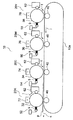
以下、本発明の実施例1について図1乃至図6を用いて説明する。図1は、例えば、プリンタ、多機能周辺機器(MFP)、ファックス、プロッターその他画像出力する任意の装置等の、本発明の実施例の画像形成装置の画像形成部10を示す概略構成図である。図1に示すように、画像形成部10は、矢印r方向に回転される転写ベルト10aを有する。転写ベルト10aに沿って、イエロ(Y)、マジェンタ(M)、シアン(C)の各カラートナー像を形成する複数のカラー画像形成ユニット20Y、20M、20C及び、ブラックトナー像を形成するブラック画像形成ユニット20Kが、タンデムに配列される。転写ベルト10aは、記録媒体であるシート紙Pを矢印s方向に搬送する。
Embodiment 1 of the present invention will be described below with reference to FIGS. FIG. 1 is a schematic configuration diagram illustrating an
ブラック画像形成ユニット20K及びシアン、マジェンタ、イエロの各カラー画像形成ユニット20C、20M、20Yは、夫々像担持体であるブラック、シアン、マジェンタ、イエロの感光体ドラム32、34、36、38を備えている。転写ベルト10aを介して、各感光体ドラム32、34、36、38と対向する位置には、それぞれ転写ローラ40が配置されている。転写ローラ40に印加する電圧は+300〜2kV程度である。
Each of the black
各感光体ドラム32、34、36、38は矢印t方向に回転される。各感光体ドラム32、34、36、38周囲には、矢印t方向の回転方向に沿って、各感光体ドラム32、34、36、38を一様に帯電する帯電器72、74、76、78、現像兼クリーニングを行う現像器、撹乱部材であるトナー撹乱部材52、54、56、58が夫々配置されている。
Each
各感光体ドラム32、34、36、38は導電性基体の上に有機系もしくはアモルファスシリコン系等の感光層を有して成っている。各感光体ドラム32、34、36、38は、帯電器72、74、76、78、にて帯電後、図示しないレーザ露光装置等により露光され静電潜像を形成される。各感光体ドラム32、34、36、38表面の静電潜像は、例えば露光部である画像部が−60Vにバイアスされ、非画像部 (即ちレーザ露光装置に露光されない非露光部)が、−400Vにバイアスされている。露光後感光体ドラム32、34、36、38は現像器62、64、66、68位置に達する。
Each of the
帯電器72、74、76、78は、感光体ドラム32、34、36、38と非接触のコロナ帯電器からなる。各帯電器72、74、76、78は、感光体ドラム32、34、36、38の表面を夫々特定のバイアス、例えば−400Vに帯電する。帯電器72、74、76、78が非接触のコロナ帯電器であることから、感光体ドラム32、34、36、38表面のトナー薄層の付着により汚染される事がない。従って帯電器72、74、76、78は、効果的な帯電性能を保持できる。
The
現像器62、64、66、68はマイナス極性のトナーを収納し、現像ローラは、予定のバイアスたとえば−250Vに設定される。現像器62、64、66、68は、露光部にトナーを供給する反転現像プロセスにおいて、新たな露光によって形成された静電潜像の露光部である−60Vの画像部にトナーを供給して現像を行う一方、先行するトナー像の転写残りであって、新たな露光によって形成された静電潜像の非露光部である−400Vの非画像部に付着する残留トナーを現像器内に回収してクリーニングを行う。
The developing
トナー撹乱部材52、54、56、58は、転写後感光体ドラム32、34、36、38に付着する残留トナーを一旦捕集した後、クリーニングのために吐き出す。トナー撹乱部材52、54、56、58は、例えば図1に示す様に固定タイプのブラシ9で、毛の長さは2〜20mm、繊維は1〜10デニール、幅は1〜10mm程度、抵抗値は10e4から10e10Ω程度である。トナー撹乱部材52、54、56、58のタイプは、固定タイプのブラシ9に限定されず、例えば図2のようなローラタイプ11でも良い。ローラタイプ11としては例えば導電性のスポンジローラ等が挙げられる。またトナー撹乱部材52、54、56、58は、図3のようなブラシローラタイプ12でも良い。
The
トナー撹乱部材52、54、56、58には、残留トナーを捕集するため例えば第1のバイアスである+600Vのバイアスが印加される。但しトナー撹乱部材52、54、56、58に捕集された残留トナーは、感光体ドラム32、34、36、38とトナー撹乱部材52、54、56、58間の機械的圧力のために、感光体ドラム32、34、36、38上にフィルミング現象を発生する恐れがある。このフィルミング現象を防止するため画像形成操作に寄与していない画像形成ユニット20K、20C、20M、20Yにおいては、トナー撹乱部材52、54、56、58のバイアスを反転してトナー撹乱部材52、54、56、58に捕集した残留トナーを吐き出す。この時画像形成操作は行なわないものの、帯電器72、74、76、78及び現像器62、64、66、68は作動している。従って、感光体ドラム32、34、36、38上に吐き出された残留トナーは、帯電器72、74、76、78によりマイナス極性に帯電され、現像器62、64、66、68に回収される。
For example, a first bias of +600 V is applied to the
残留トナーを吐き出すため、トナー撹乱部材52、54、56、58に印加するバイアスを、例えば+600Vから第2のバイアスである−600Vまで変更する。バイアスは例えば制御部(図示せず)により+600Vから−600Vに変更制御される。制御部は、ハードウェア、ソフトウェア或いはそれらのいくつかの組み合わせで構成されている。たとえば制御部は、CPUまたはマイクロプロセッサおよび、ROMまたはNVRAMのようなメモリを具備している。メモリは、バイアスを変更制御するため、CPUまたはマイクロプロセッサにより実行される命令を記憶している。
In order to discharge the residual toner, the bias applied to the
バイアスの変更制御は、瞬時あるいは、たとえば1000V/s以下というような特定の変更速度でなされる。バイアスを+600Vから−600Vに瞬時に切替えると、ブラシ9から一度に大量の残留トナーが吐き出されてしまう。このため現像器62、64、66、68で残留トナーを回収しきれず、画像汚れを発生する場合がある。これを防止するためには、特定の変更速度をもたせてバイアスを切り替える。特定の変更速度でバイアスを切り替えると、感光体ドラム32、34、36、38上には、残留トナーにより、一様のトナー薄層が形成される。次いで現像器62、64、66、68が感光体ドラム32、34、36、38上のトナー薄層を確実に回収することとなる。感光体ドラム32、34、36、38上のトナー薄厚は、感光体ドラム32、34、36、38の周速及び、トナー撹乱部材52、54、56、58のバイアスの変更速度により調整可能である。
The bias change control is performed instantaneously or at a specific change speed such as 1000 V / s or less. When the bias is instantaneously switched from +600 V to −600 V, a large amount of residual toner is discharged from the
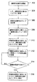
次に図4に示すフローチャートを参照して作用について述べる。画像形成操作の開始(ステップ302)により所定の画像形成ユニット20K、20C、20M、20Yにて画像形成操作を行う。画像形成操作は、たとえばコピージョブ、プリントジョブ、ファックスジョブまたはプリントアウトできるその他の操作である。画像形成操作は、たとえば画像形成装置のコントロールパネル(図示せず)を介して、或いはプリントリクエストまたは受信したファックスのようなネットワークまたは他の通信ライン等を介して画像形成装置が受信した画像情報に応じて開始される。
Next, the operation will be described with reference to the flowchart shown in FIG. By starting the image forming operation (step 302), the image forming operation is performed in the predetermined
画像形成操作は、フルカラー画像、モノクロ画像または複数の画像形成ユニット20K、20C、20M、20Yのいずれか一つまたは幾つかを組み合わせて実施される各種画像を形成する操作である。フルカラー画像の場合は、全ての画像形成ユニット20K、20C、20M、20Yが使用される。モノクロ画像の場合はブラック画像形成ユニット20Kのみが使用される。更に単色カラー画像(モノクロ画像以外)、その他2色刷り等の場合は所望の画像形成ユニット20K、20C、20M、20Yが幾つか使用される。
The image forming operation is an operation for forming various images performed by combining a full-color image, a monochrome image, or a plurality of
ステップ302に続いて、制御部は、トナー撹乱部材52、54、56、58に印加するバイアスを第1のバイアスである+600Vに設定する(ステップ304)。第1のバイアスを印加されたトナー撹乱部材52、54、56、58は残留トナーを引き付け捕集する。トナー撹乱部材52、54、56、58は、画像形成操作の開始に応じて第1のバイアスに設定されるが、そうでない場合は節電のため、例えば0Vに初期設定されても良い。
Following
次に制御部は、画像形成操作のタイプを決定する(ステップ306)。画像形成操作のタイプとは、フルカラー画像タイプ、モノクロ画像タイプあるいは単色カラー画像タイプ等をいう。これにより画像形成操作に寄与しない画像形成ユニット20K、20C、20M、20Yを判別する(ステップ308)。例えばフルカラー画像タイプの場合、全ての画像形成ユニット20K、20C、20M、20Yが画像形成操作に寄与するが、モノクロ画像タイプであれば、カラー画像形成ユニット20C、20M、20Yは、全て画像形成操作に寄与しない。また単色カラー画像タイプであれば、ブラック画像形成ユニット20Kおよびカラー画像形成ユニット20C、20M、20Yの内のあるものは画像形成操作に寄与しない。
Next, the control unit determines the type of image forming operation (step 306). The type of image forming operation refers to a full color image type, a monochrome image type, a single color image type, or the like. As a result, the
画像形成操作に寄与しない画像形成ユニット20K、20C、20M、20Yにおいて、制御部は、トナー撹乱部材52、54、56、58に印加するバイアスを、第2のバイアスである−600Vに変更する(ステップ310)。第2のバイアスに変更されることにより、トナー撹乱部材52、54、56、58は捕集した残留トナーを、感光体ドラム32、34、36、38表面に吐き出す。第1のバイアスから第2のバイアスへの変更は徐々に行われることが好ましい。本実施例では、たとえばその変更は、1000V/sec以下で行う。トナー撹乱部材52、54、56、58に印加するバイアス値を徐々に変更することは、感光体ドラム32、34、36、38表面上に残留トナーを一様に拡散するのに役立つ。回転される感光体ドラム32、34、36、38表面上に一様に拡散された残留トナーは、夫々の現像器62、64、66、68によって確実に除去される。
In the
モノクロ画像であれば、カラー画像形成ユニット20C、20M、20Yは、全て画像形成操作に寄与しないが、ステップ310は、全てのカラー画像形成ユニット20C、20M、20Yに適用しなくても、カラー画像形成ユニット20C、20M、20Yの内の残留トナーの回収を必要とするもののみ行えば良い。更に、単色カラー画像あるいは2色刷り等のカラー画像を形成する場合には、画像形成操作に寄与している場合であっても、画像形成操作を行っている間の空いているタイミングにステップ310を行っても良い。
If the image is a monochrome image, the color
またトナー撹乱部材52、54、56、58にてステップ310を実行した画像形成ユニット20K、20C、20M、20Yに有っては、現像器62、64、66、68の現像ローラの回転速度を変更する(ステップ312)。画像形成操作時に比べて現像ローラの回転速度が高速となるように変更する。例えば現像時に感光体ドラム32、34、36、38と同方向に速度比1.5倍でWith回転している現像ローラの周速を、クリーニング時には、感光体ドラム32、34、36、38との速度比が2倍になるよう変更する。これにより現像器62、64、66、68による残留トナーの回収性能を向上できる。従って現像器62、64、66、68で回収しきれない未回収のトナーによる感光体ドラム32、34、36、38の汚損を防止出来、画像汚れのない良好な画像を得られる。
Further, in the
即ちステップ302の画像形成操作の開始により画像形成操作に寄与する何れかの感光体ドラム32、34、36、38は矢印t方向に回転される。転写ベルト11は矢印r方向に回転される。各感光体ドラム32、34、36、38は帯電器72、74、76、78により夫々−400Vに一様に帯電される。次いで感光体ドラム32、34、36、38は、露光装置により、各色の画像情報に対応する露光々を照射され静電潜像を形成される。
That is, any of the
次いで現像器62、64、66、68にあっては、現像時の速度で回転する現像ローラにより、感光体ドラム32、34、36、38上の静電潜像の露光部である画像部を現像してトナー像を形成すると同時に、非露光部である非画像部に付着するトナーを現像器62、64、66、68内に回収して、現像同時クリーニングを行う。但し、このとき先行する画像形成操作による、感光体ドラム32、34、36、38上の残留トナーの大部分はトナー撹乱部材52、54、56、58に捕集されていて、感光体ドラム32、34、36、38の非画像部の付着トナーは少ない。
Next, in the developing
感光体ドラム32、34、36、38に形成されたトナー像は、転写ローラ40により転写バイアスを印加されて、転写ベルト10a上の矢印s方向に搬送されるシート紙Pに転写される。所望のトナー像を形成されたシート紙Pは、定着装置を経て画像を完成される。
The toner images formed on the
一方転写終了後感光体ドラム32、34、36、38は、トナー撹乱部材52、54、56、58に達する。この時トナー撹乱部材52、54、56、58は+600Vのバイアスを印加されていて、感光体ドラム32、34、36、38上の残留トナーをブラシ9にて捕集する。次いで感光体ドラム32、34、36、38は、次の画像形成操作を成される。
On the other hand, after the transfer is completed, the
一方画像形成操作に寄与しない何れかの画像形成ユニット20K、20C、20M、20Yに有っても、ステップ302の画像形成操作の開始により感光体ドラム32、34、36、38は矢印t方向に回転される。但し、露光装置による露光は行われない。画像形成操作に寄与しない画像形成ユニット20K、20C、20M、20Yでは、ステップ310により1000V/sの変更速度でトナー撹乱部材52、54、56、58のバイアスが変更され、感光体ドラム32、34、36、38表面上に残留トナーを徐々に且つ一様に吐き出す。また現像器62、64、66、68では、ステップ312により、現像ローラが高速に回転され、感光体ドラム32、34、36、38表面上に吐き出された残留トナーを確実に回収する。
On the other hand, even in any of the
次いでステップ314で、全ての画像形成操作を終了したかをチェックする。残留トナーのクリーニングを行ったトナー撹乱部材52、54、56、58にあっては、全ての画像形成操作が終了するまで、トナー撹乱部材52、54、56、58に印加するバイアスを、−600Vに保持する。画像形成操作が全て終了したら、ステップ316に進み、クリーニングのために第2のバイアスに設定されているトナー撹乱部材52、54、56、58のバイアスを第1のバイアスに復帰する。この時、例えば節電のためにトナー撹乱部材52、54、56、58のバイアスを初期設定である0Vとしても良い。この後、画像形成時にはステップ302〜ステップ316を繰り返す。
Next, in
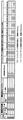
次に本実施例のサンプル例によるフィルミング防止効果及び比較例のライフ試験を行ったところ図5及び図6に示す結果を得られた。○○は、フィルミングによる画像欠陥なし、モノクロ画像の汚れなし、○×は、フィルミングによる画像欠陥なし、モノクロ画像の汚れが発生、×○は、フィルミングによる画像欠陥発生、モノクロ画像の汚れなし、××は、フィルミングによる画像欠陥、モノクロ画像の汚れともに発生を夫々示す。 Next, the filming prevention effect of the sample example of this example and the life test of the comparative example were performed, and the results shown in FIGS. 5 and 6 were obtained. ○○: no image defect due to filming, no monochrome image stain, ○ ×: no image defect due to filming, monochrome image stain, × ○: image defect caused by filming, monochrome image stain None and xx indicate the occurrence of both image defects due to filming and smudges in monochrome images.
先ず画像形成条件として、A4サイズのシート紙Pにマゼンタ(M)とシアン(C)画像を夫々20%程度の印字率にて20枚形成する。次いでモノクロ画像を20%の印字率で5枚形成する。この画像形成操作を繰り返して連続画像形成する。画像形成後、マジェンタ画像形成ユニット20Mの感光体ドラム36と、シアン画像形成ユニット20Cの感光体ドラム34のフィルミング現象を原因とする画像劣化を目視評価した。
First, as image forming conditions, 20 sheets of magenta (M) and cyan (C) images are formed on an A4 size sheet P at a printing rate of about 20%. Next, five monochrome images are formed at a printing rate of 20%. This image forming operation is repeated to form a continuous image. After image formation, image degradation caused by filming phenomenon on the
比較例である(試験No.1)では、モノクロ画像形成時においても、シアン・マゼンタのカラー画像形成ユニット20C、20Mのトナー撹乱部材54、56のバイアスを、画像形成操作時の第1のバイアスである+600Vに保持した。この結果、モノクロ画像形成時にトナー撹乱部材54、56にて、残留トナーを吐き出さなかったことから、およそ10,000枚の画像形成後に、フィルミング現象により画像筋や画像抜けが発生した。
In the comparative example (Test No. 1), even when a monochrome image is formed, the bias of the
サンプル例である(試験No.2)では、モノクロ画像形成時にトナー撹乱部材54、56のバイアスを、第1のバイアスである+600Vから第2のバイアスである−600Vに瞬時に変更した。この結果、マゼンタ(M)とシアン(C)いずれにおいても20,000枚まで、フィルミング現象が発生しなかった。
In the sample example (Test No. 2), the bias of the
比較例である(試験No.3)では、モノクロ画像形成時にトナー撹乱部材54、56のバイアスを反転させずに、第1のバイアスである+600Vから0Vへ、10Hz程度の間隔で、連続してON−OFF制御した。この結果、マゼンタ(M)とシアン(C)いずれにおいても20,000枚まで、フィルミング現象が発生しなかった。
In the comparative example (Test No. 3), the
次に画像形成条件として、シアン(C)画像を20枚では無く40枚連続画像形成後、モノクロ画像を5枚連続画像形成し、(試験No.1)〜(試験No.3)と同様に画像劣化を目視評価した。 Next, as image forming conditions, after forming 40 continuous images of cyan (C) images instead of 20 images, 5 continuous images of monochrome images were formed, as in (Test No. 1) to (Test No. 3). Image degradation was evaluated visually.
比較例である(試験No.4)では、モノクロ画像形成時にトナー撹乱部材54、56のバイアスを、第1のバイアスである+600Vから第2のバイアスである−600Vに瞬時に変更した。この結果、ブラシ9から一度に大量の残留トナーが吐き出されてしまい、現像器64で感光体ドラム34上の残留トナーを回収しきれずに、モノクロ画像形成時の1〜2枚目にシアン(C)色の汚れが発生した。
In the comparative example (Test No. 4), the bias of the
サンプル例である(試験No.5)では、モノクロ画像形成時にのみ現像器64の現像ローラの周速を通常の感光体ドラム34に対する速度比1.5倍から2倍に切り替える。この結果、モノクロ画像の汚れはほとんど見られなくなった。また15,000枚まで、フィルミング現象が発生しなかった。
In the sample example (Test No. 5), the peripheral speed of the developing roller of the developing device 64 is switched from a speed ratio of 1.5 times to 2 times that of the normal
また感光体ドラム34への大量のトナーの放出を防止するため、(試験No.6)〜(試験No.12)では、トナー撹乱部材54の第1のバイアスである+600Vから、第2のバイアスである−600Vへ切り替える変更速度を変化させた。比較例である(試験No.6)は、+600Vから−600Vへ、0.6秒かけて切り替えた。比較例である(試験No.7)は、0.8秒、比較例である(試験No.8)は、1.0秒、サンプル例である(試験No.9)は、1.2秒、サンプル例である(試験No.10)は、1.4秒かけて切り替えた。この結果(試験No.6)〜(試験No.8)の切り変え時間1.0秒までは若干の汚れが発生したが、(試験No.9)の1.2秒及び(試験No.10)の1.4秒では、汚れがほぼ発生しなかった。また(試験No.9)及び(試験No.10)では15,000枚まで、フィルミング現象が発生しなかった。
In order to prevent a large amount of toner from being released to the
また比較例である(試験No.11)及び、サンプル例である(試験No.12)では第1のバイアスを+300Vとして、モノクロ画像形成時にトナー撹乱部材54、56のバイアスを、第1のバイアスである+300Vから第2のバイアスである−600Vに切り替えた。この結果切り替え時間が0.7秒の(試験No.11)では汚れが発生したが、0.9秒の(試験No.12)では画像汚れが発生しなかった。
In the comparative example (Test No. 11) and the sample example (Test No. 12), the first bias is set to +300 V, and the bias of the
(試験No.1)〜(試験No.12)の結果から、トナー撹乱部材のバイアスを第1のバイアスから第2のバイアスへ切り替える変更速度を1000V/sec以下とすれば、良好なクリーニングを得られることが判明した。 From the results of (Test No. 1) to (Test No. 12), good cleaning can be obtained if the change speed at which the bias of the toner disturbing member is switched from the first bias to the second bias is 1000 V / sec or less. Turned out to be.
次に画像形成条件として、A4サイズのシート紙Pにマゼンタ(M)とシアン(C)画像を夫々20%の印字率にて20枚連続画像形成した後、シアン(C)のみ20%の印字率で5枚画像形成する。この画像形成操作を繰り返した際のブラック画像形成ユニット20Kの感光体ドラム32とマジェンタ画像形成ユニット20Mの感光体ドラム36のフィルミング現象を原因とする画像劣化を目視評価した。
Next, as image forming conditions, after 20 sheets of magenta (M) and cyan (C) images were continuously formed on an A4 size sheet paper P at a printing rate of 20%, only cyan (C) was printed at 20%. 5 images are formed at a rate. When this image forming operation was repeated, the image deterioration caused by the filming phenomenon of the
比較例である(試験No.13)では、シアン画像形成時においても、マジェンタのカラー画像形成ユニット20Mのトナー撹乱部材56のバイアスを、変更せずに画像形成操作時の第1のバイアスである+600Vに保持した。この結果、マジェンタの感光体ドラム36ではおよそ10,000枚の画像形成後に、フィルミングが発生し、画像筋や画像抜けが発生した。
In the comparative example (Test No. 13), even when a cyan image is formed, the bias of the
サンプル例である(試験No.14)では、ブラックの画像形成ユニット20の感光体ドラム32について(試験No.13)と同様の評価を行なった。この結果、ブラックの感光体ドラム32では、10,000枚の画像形成では画質劣化は発生せず、12,500枚近辺で、フィルミング現象により画像筋や画像抜けが発生した。
In the sample example (Test No. 14), the same evaluation as (Test No. 13) was performed on the
(試験No.13)及び(試験No.14)から、ブラックトナーに比べてカラートナーの方がフィルミング現象を生じやすいことが判明した。 From (Test No. 13) and (Test No. 14), it was found that the color toner is more likely to cause the filming phenomenon than the black toner.
サンプル例である(試験No.15)では、シアン画像形成時に、マジェンタ画像形成ユニット20Mのトナー撹乱部材56のバイアスを、第1のバイアスである+600Vから第2のバイアスである−600Vに1000V/secの変更速度で切り替えた。この結果、マジェンタの感光体ドラム36では20,000枚まで、フィルミング現象が発生しなかった。
In the sample example (Test No. 15), during cyan image formation, the bias of the
サンプル例である(試験No.16)では、シアン画像形成時に、ブラック画像形成ユニット20Kのトナー撹乱部材52のバイアスを、第1のバイアスである+600Vから第2のバイアスである−600Vに1000V/secの変更速度で切り替えた。この結果、ブラックの感光体ドラム32では22,500枚まで、フィルミング現象が発生しなかった。マジェンタの感光体ドラム36に比べてブラックの感光体ドラム32はフィルミングを発生しにくかった。
In the sample example (Test No. 16), during cyan image formation, the bias of the
上記(試験No.1)〜(試験No.16)から、画像形成操作を行なう間の早いタイミングで、画像形成操作に寄与しない画像形成ユニット20K、20C、20M、20Yにて、トナー撹乱部材52、54、56、58に印加するバイアスを、第1のバイアスから第2のバイアスに切り替えて、トナー撹乱部材52、54、56、58に捕集した残留トナーを現像器62、64、66、68に回収することにより、感光体ドラム32、34、36、38表面のフィルミングの発生を遅らせることができることが判明した。
From the above (Test No. 1) to (Test No. 16), the
本実施例によれば、複数の画像形成ユニット20K、20C、20M、20Yを有するタンデム方式の画像形成装置において、画像形成操作に寄与しないトナー撹乱部材52、54、56、58のバイアスをトナー捕集時の第1のバイアスからトナーを吐き出す第2のバイアスに切り替えて、トナー捕集後、早いタイミングでトナーを吐き出す。次いで感光体ドラム32、34、36、38表面に吐き出されたトナーを現像兼クリーニングを行なう現像器で回収している。これにより、トナー撹乱部材52、54、56、58位置にて、感光体ドラム32、34、36、38表面にトナーが長く接するのを防止でき、ひいては感光体ドラム32、34、36、38表面のフィルミング現象の発生を防止出来、その長寿命化を得られる。
According to the present embodiment, in the tandem image forming apparatus having a plurality of
更に本実施例では、第1のバイアスから第2のバイアスへの切り替えを所定の変更速度により徐々におこなう。これによりトナー撹乱部材52、54、56、58から一度に大量のトナーを吐き出すことなく、感光体ドラム32、34、36、38上に一様のトナー薄層を形成可能となる。従って現像器62、64、66、68にて感光体ドラム32、34、36、38上のトナーを効率的に確実に回収でき、感光体ドラム32、34、36、38の汚れによる画像汚れを防止出来る。
Further, in this embodiment, switching from the first bias to the second bias is gradually performed at a predetermined change speed. Thus, a uniform toner thin layer can be formed on the
尚本発明は上記実施例に限られるものではなく、この発明の範囲内で種々変形可能であり、例えば画像形成装置は直接転写方式でなく、中間転写部を設けて、トナー像の転写を行なうものであってよい。又タンデム方式の画像形成装置の画像形成ユニットの数や現像剤の色あるいはその配列順等限定されない。又、トナー撹乱部材に印加する第1のバイアス値は、残留トナーを捕集可能であれば良いし、又第2のバイアス値はトナー撹乱部材に捕集したトナーを像担持体に吐き出されば良い。又第1のバイアス値から第2のバイアス値に変更する場合の変更速度も任意である。 The present invention is not limited to the above-described embodiments, and various modifications can be made within the scope of the present invention. For example, the image forming apparatus is not a direct transfer system, and an intermediate transfer portion is provided to transfer a toner image. It may be a thing. Further, the number of image forming units of the tandem type image forming apparatus, the color of the developer, or the arrangement order thereof are not limited. The first bias value to be applied to the toner disturbing member may be any value as long as the residual toner can be collected, and the second bias value may be determined if the toner collected by the toner disturbing member is discharged to the image carrier. good. Further, the changing speed when changing from the first bias value to the second bias value is also arbitrary.
又画像形成操作に寄与していない現像器でのクリーニング時に、トナーとの電位差を高めるように現像バイアスを制御して、現像ローラによるトナー回収能力を更に高めるようにしても良い。更に帯電器の構造も限定されないが、トナーによる汚損を防止するためには、非接触タイプの帯電器がより好ましい。 Further, at the time of cleaning with a developing unit that does not contribute to the image forming operation, the developing bias may be controlled so as to increase the potential difference with the toner, and the toner collecting ability by the developing roller may be further enhanced. Further, the structure of the charger is not limited, but a non-contact type charger is more preferable in order to prevent contamination by toner.
10…画像形成部
10a…転写ベルト
20K…ブラック画像形成ユニット
20C、20M、20Y…カラー画像形成ユニット
32、34、36、38…感光体ドラム
32、34、36、38…ブラック用感光体ドラム
52、54、56、58…トナー撹乱部材
62、64、66、68…現像器
72、74、76、78…帯電器
DESCRIPTION OF
Claims (19)
前記画像形成操作中の前記画像形成ユニットの前記撹乱部材に第1のバイアスを印加する工程と、
前記画像形成操作に寄与しない少なくとも1つの前記画像形成ユニットでは、前記撹乱部材に印加するバイアスを前記第1のバイアスとは異なる第2のバイアスに変更する工程とを具備することを特徴とする画像形成方法。 Recording is performed by performing an image forming operation using at least one image forming unit in an image forming apparatus having a plurality of image forming units each having an image carrier and a disturbing member facing the image carrier. In an image forming method for forming a toner image on a medium,
Applying a first bias to the disturbing member of the image forming unit during the image forming operation;
The at least one image forming unit that does not contribute to the image forming operation includes a step of changing a bias applied to the disturbance member to a second bias different from the first bias. Forming method.
前記ブラック画像形成ユニットが前記画像形成操作に寄与するモノクロ画像形成を実施する間に、前記カラー画像形成ユニットにて前記撹乱部材に印加するバイアスを前記第2のバイアスに変更することを特徴とする請求項1記載の画像形成方法。 The plurality of image forming units are a black image forming unit that forms a black toner image and a color image forming unit that forms at least one color toner image,
While the black image forming unit performs monochrome image formation that contributes to the image forming operation, the bias applied to the disturbance member in the color image forming unit is changed to the second bias. The image forming method according to claim 1.
前記画像形成操作の完了後、前記撹乱部材に印加するバイアスを、前記第2のバイアスから前記第1のバイアスに戻す工程とを更に具備する事を特徴とする請求項1記載の画像形成方法。 Detecting the completion of the image forming operation;
The image forming method according to claim 1, further comprising a step of returning a bias applied to the disturbance member from the second bias to the first bias after completion of the image forming operation.
カラー画像形成のために前記複数のカラー画像形成ユニットのいずれかが前記画像形成操作中に、前記画像形成操作に寄与していない前記カラー画像形成ユニットの前記撹乱部材に印加するバイアスを、前記第2のバイアスに変更することを特徴とする請求項1記載の画像形成方法。 The plurality of image forming units are a plurality of color image forming units that form different color toner images,
A bias applied to the disturbing member of the color image forming unit that does not contribute to the image forming operation during the image forming operation by any of the plurality of color image forming units for forming a color image. The image forming method according to claim 1, wherein the bias is changed to 2.
画像形成操作中の前記画像形成ユニットでは前記撹乱部材を第1のバイアスに印加制御し、前記画像形成操作に寄与しない少なくとも1つの前記画像形成ユニットでは前記撹乱部材に印加するバイアスを前記第1のバイアスとは異なる第2のバイアスに変更制御する制御部とを具備することを特徴とする画像形成装置。 An image carrier, a charger that uniformly charges the image carrier, a developer that performs development and cleaning on the image carrier, and a disturbance that disturbs residual toner on the image carrier after transfer A plurality of image forming units having members;
In the image forming unit during the image forming operation, the disturbance member is controlled to be applied to the first bias, and in at least one image forming unit that does not contribute to the image forming operation, the bias applied to the disturbance member is the first bias. An image forming apparatus comprising: a control unit that controls to change to a second bias different from the bias.
前記ブラック画像形成ユニットが前記画像形成操作に寄与するモノクロ画像形成を実施する間に、前記制御部は、前記カラー画像形成ユニットにて前記撹乱部材に印加するバイアスを前記第2のバイアスに変更することを特徴とする請求項12記載の画像形成装置。 The plurality of image forming units are a black image forming unit that forms a black toner image and a color image forming unit that forms at least one color toner image,
While the black image forming unit performs monochrome image formation that contributes to the image forming operation, the control unit changes the bias applied to the disturbance member in the color image forming unit to the second bias. The image forming apparatus according to claim 12.
Applications Claiming Priority (1)
| Application Number | Priority Date | Filing Date | Title |
|---|---|---|---|
| US11/091,600 US7349652B2 (en) | 2005-03-29 | 2005-03-29 | Apparatus and method for cleaning residual toner from drums in image forming apparatus |
Publications (1)
| Publication Number | Publication Date |
|---|---|
| JP2006276830A true JP2006276830A (en) | 2006-10-12 |
Family
ID=37070648
Family Applications (1)
| Application Number | Title | Priority Date | Filing Date |
|---|---|---|---|
| JP2005334117A Pending JP2006276830A (en) | 2005-03-29 | 2005-11-18 | Image forming method and image forming apparatus |
Country Status (2)
| Country | Link |
|---|---|
| US (3) | US7349652B2 (en) |
| JP (1) | JP2006276830A (en) |
Families Citing this family (4)
| Publication number | Priority date | Publication date | Assignee | Title |
|---|---|---|---|---|
| US7349652B2 (en) * | 2005-03-29 | 2008-03-25 | Kabushiki Kaisha Toshiba | Apparatus and method for cleaning residual toner from drums in image forming apparatus |
| US7796918B2 (en) * | 2006-07-05 | 2010-09-14 | Kabushiki Kaisha Toshiba | Image forming apparatus and its cleaner unit, and cleaner unit replacement method of the image forming apparatus |
| JP4963717B2 (en) * | 2009-09-02 | 2012-06-27 | キヤノン株式会社 | Development device |
| KR20150040121A (en) * | 2013-10-04 | 2015-04-14 | 삼성전자주식회사 | electrophotographic image forming apparatus |
Citations (7)
| Publication number | Priority date | Publication date | Assignee | Title |
|---|---|---|---|---|
| JPS6115169A (en) * | 1984-06-30 | 1986-01-23 | Casio Comput Co Ltd | Image forming device |
| JPH0980907A (en) * | 1995-09-19 | 1997-03-28 | Pfu Ltd | Electrophotographic printer |
| JPH09325607A (en) * | 1996-05-31 | 1997-12-16 | Fuji Xerox Co Ltd | Image forming device |
| JP2000267384A (en) * | 1999-03-18 | 2000-09-29 | Canon Inc | Image forming device |
| JP2003280318A (en) * | 2002-03-25 | 2003-10-02 | Canon Inc | Multicolor image forming device |
| JP2004191579A (en) * | 2002-12-10 | 2004-07-08 | Sharp Corp | Foreign matter removing mechanism, printing apparatus, and foreign matter removing method |
| JP2006195243A (en) * | 2005-01-14 | 2006-07-27 | Konica Minolta Business Technologies Inc | Image forming apparatus |
Family Cites Families (22)
| Publication number | Priority date | Publication date | Assignee | Title |
|---|---|---|---|---|
| US4664504A (en) * | 1983-01-20 | 1987-05-12 | Tokyo Shibaura Denki Kabushiki Kaisha | Image forming apparatus |
| US4763168A (en) * | 1983-03-02 | 1988-08-09 | Xerox Corporation | Reproducing apparatus including toner removal apparatus utilizing electrostatic attraction |
| US5124757A (en) * | 1990-06-25 | 1992-06-23 | Minolta Camera Kabushiki Kaisha | Image forming method and apparatus including treatment and collection of residual developer |
| US5576810A (en) * | 1994-10-03 | 1996-11-19 | Canon Kabushiki Kaisha | Image forming method |
| JP3385134B2 (en) * | 1994-11-14 | 2003-03-10 | 株式会社沖データ | Electrophotographic recording device |
| JP3342217B2 (en) | 1995-01-18 | 2002-11-05 | キヤノン株式会社 | Image forming device |
| EP0726503B1 (en) * | 1995-02-10 | 2003-11-19 | Canon Kabushiki Kaisha | Image-forming method and image-forming apparatus |
| US5822657A (en) * | 1996-05-16 | 1998-10-13 | Brother Kogyo Kabushiki Kaisha | Image forming apparatus |
| JPH1031360A (en) * | 1996-07-17 | 1998-02-03 | Matsushita Electric Ind Co Ltd | Image forming device |
| JP3752820B2 (en) * | 1998-02-27 | 2006-03-08 | コニカミノルタビジネステクノロジーズ株式会社 | Color image forming apparatus |
| JP3337994B2 (en) * | 1999-01-26 | 2002-10-28 | キヤノン株式会社 | Image forming device |
| JP2001117424A (en) * | 1999-10-15 | 2001-04-27 | Canon Inc | Image forming device |
| JP2003076215A (en) * | 2001-09-04 | 2003-03-14 | Canon Inc | Image forming device |
| JP4289914B2 (en) * | 2002-05-07 | 2009-07-01 | キヤノン株式会社 | Imaging optical system and image reading apparatus using the same |
| JP2004198957A (en) * | 2002-12-20 | 2004-07-15 | Katsuragawa Electric Co Ltd | Image forming device |
| US6920300B2 (en) * | 2003-03-12 | 2005-07-19 | Kabushiki Kaisha Toshiba | Image forming apparatus capable of inhibiting photoreceptor filming and color toner mixing |
| JP2005107190A (en) * | 2003-09-30 | 2005-04-21 | Toshiba Tec Corp | Image forming apparatus |
| US20060088343A1 (en) * | 2004-10-25 | 2006-04-27 | Kabushiki Kaisha Toshiba | Image forming apparatus and image forming method |
| US7426358B2 (en) * | 2005-03-17 | 2008-09-16 | Kabushiki Kaisha Toshiba | Image forming apparatus and method having a cleanerless image forming unit |
| US7266332B2 (en) * | 2005-03-17 | 2007-09-04 | Kabushiki Kaisha Toshiba | Image forming apparatus for recycling toner |
| US7428395B2 (en) * | 2005-03-21 | 2008-09-23 | Kabushiki Kaisha Toshiba | Image forming apparatus equipped with developing unit to make developing and simultaneous cleaning and image forming method |
| US7349652B2 (en) * | 2005-03-29 | 2008-03-25 | Kabushiki Kaisha Toshiba | Apparatus and method for cleaning residual toner from drums in image forming apparatus |
-
2005
- 2005-03-29 US US11/091,600 patent/US7349652B2/en not_active Expired - Lifetime
- 2005-11-18 JP JP2005334117A patent/JP2006276830A/en active Pending
-
2007
- 2007-02-22 US US11/677,807 patent/US7486913B2/en not_active Expired - Lifetime
-
2009
- 2009-01-08 US US12/350,540 patent/US7715758B2/en not_active Expired - Lifetime
Patent Citations (7)
| Publication number | Priority date | Publication date | Assignee | Title |
|---|---|---|---|---|
| JPS6115169A (en) * | 1984-06-30 | 1986-01-23 | Casio Comput Co Ltd | Image forming device |
| JPH0980907A (en) * | 1995-09-19 | 1997-03-28 | Pfu Ltd | Electrophotographic printer |
| JPH09325607A (en) * | 1996-05-31 | 1997-12-16 | Fuji Xerox Co Ltd | Image forming device |
| JP2000267384A (en) * | 1999-03-18 | 2000-09-29 | Canon Inc | Image forming device |
| JP2003280318A (en) * | 2002-03-25 | 2003-10-02 | Canon Inc | Multicolor image forming device |
| JP2004191579A (en) * | 2002-12-10 | 2004-07-08 | Sharp Corp | Foreign matter removing mechanism, printing apparatus, and foreign matter removing method |
| JP2006195243A (en) * | 2005-01-14 | 2006-07-27 | Konica Minolta Business Technologies Inc | Image forming apparatus |
Also Published As
| Publication number | Publication date |
|---|---|
| US20090116887A1 (en) | 2009-05-07 |
| US7349652B2 (en) | 2008-03-25 |
| US7715758B2 (en) | 2010-05-11 |
| US7486913B2 (en) | 2009-02-03 |
| US20070140734A1 (en) | 2007-06-21 |
| US20060222404A1 (en) | 2006-10-05 |
Similar Documents
| Publication | Publication Date | Title |
|---|---|---|
| JP5173239B2 (en) | Image forming apparatus | |
| JP3919641B2 (en) | Image forming apparatus | |
| JP2008191597A (en) | Image forming apparatus | |
| JP7071163B2 (en) | Image forming device | |
| JP2019164229A (en) | Image formation apparatus | |
| JP2006119604A (en) | Image forming apparatus | |
| JPH07271211A (en) | Image forming device | |
| US7715758B2 (en) | Apparatus and method for cleaning residual toner from drums in an image forming apparatus | |
| JP2019174765A (en) | Image formation device | |
| JP2003345212A (en) | Image forming device | |
| JP2000147914A (en) | Image forming device | |
| JP2002372902A (en) | Image forming device | |
| JP2009271148A (en) | Image forming apparatus | |
| JP3950804B2 (en) | Image forming apparatus | |
| JP2002365943A (en) | Imaging device | |
| JP4379722B2 (en) | Image forming apparatus | |
| JP3848207B2 (en) | Image forming apparatus | |
| JP2006163301A (en) | Image forming apparatus | |
| JPH11167293A (en) | Image forming device | |
| JP4744240B2 (en) | Image forming apparatus cleaning device | |
| JP2012042802A (en) | Image forming apparatus | |
| JP2006337684A (en) | Image forming apparatus | |
| JP2005258321A (en) | Image forming apparatus | |
| JP4984778B2 (en) | Image forming apparatus | |
| JP2003263010A (en) | Electrifying member cleaning device and image forming apparatus |
Legal Events
| Date | Code | Title | Description |
|---|---|---|---|
| A621 | Written request for application examination |
Free format text: JAPANESE INTERMEDIATE CODE: A621 Effective date: 20070919 |
|
| A131 | Notification of reasons for refusal |
Free format text: JAPANESE INTERMEDIATE CODE: A131 Effective date: 20100309 |
|
| A521 | Written amendment |
Free format text: JAPANESE INTERMEDIATE CODE: A523 Effective date: 20100507 |
|
| A02 | Decision of refusal |
Free format text: JAPANESE INTERMEDIATE CODE: A02 Effective date: 20100720 |