JP2006281175A - Electrochemical microreactor and manufacturing method using the same - Google Patents
Electrochemical microreactor and manufacturing method using the same Download PDFInfo
- Publication number
- JP2006281175A JP2006281175A JP2005108460A JP2005108460A JP2006281175A JP 2006281175 A JP2006281175 A JP 2006281175A JP 2005108460 A JP2005108460 A JP 2005108460A JP 2005108460 A JP2005108460 A JP 2005108460A JP 2006281175 A JP2006281175 A JP 2006281175A
- Authority
- JP
- Japan
- Prior art keywords
- microreactor
- electrode
- reaction
- electrodes
- electrochemical
- Prior art date
- Legal status (The legal status is an assumption and is not a legal conclusion. Google has not performed a legal analysis and makes no representation as to the accuracy of the status listed.)
- Pending
Links
- 238000004519 manufacturing process Methods 0.000 title claims abstract description 18
- 238000003487 electrochemical reaction Methods 0.000 claims abstract description 21
- 239000007788 liquid Substances 0.000 claims abstract description 18
- 239000000126 substance Substances 0.000 claims abstract description 15
- 238000006471 dimerization reaction Methods 0.000 claims description 5
- 238000006243 chemical reaction Methods 0.000 description 39
- 238000000034 method Methods 0.000 description 22
- 239000000758 substrate Substances 0.000 description 15
- 238000006722 reduction reaction Methods 0.000 description 13
- 239000000243 solution Substances 0.000 description 13
- 239000010408 film Substances 0.000 description 11
- 238000007254 oxidation reaction Methods 0.000 description 11
- -1 glassy carbon Chemical compound 0.000 description 10
- 230000003647 oxidation Effects 0.000 description 9
- 239000003115 supporting electrolyte Substances 0.000 description 8
- 238000012546 transfer Methods 0.000 description 8
- 238000009792 diffusion process Methods 0.000 description 7
- 239000000463 material Substances 0.000 description 7
- 239000012528 membrane Substances 0.000 description 7
- 229910052751 metal Inorganic materials 0.000 description 7
- 239000002184 metal Substances 0.000 description 7
- OKTJSMMVPCPJKN-UHFFFAOYSA-N Carbon Chemical compound [C] OKTJSMMVPCPJKN-UHFFFAOYSA-N 0.000 description 6
- OKKJLVBELUTLKV-UHFFFAOYSA-N Methanol Chemical compound OC OKKJLVBELUTLKV-UHFFFAOYSA-N 0.000 description 6
- 239000012530 fluid Substances 0.000 description 6
- 239000002904 solvent Substances 0.000 description 6
- NIXOWILDQLNWCW-UHFFFAOYSA-N acrylic acid group Chemical group C(C=C)(=O)O NIXOWILDQLNWCW-UHFFFAOYSA-N 0.000 description 5
- 238000004544 sputter deposition Methods 0.000 description 5
- 238000004458 analytical method Methods 0.000 description 4
- 239000006227 byproduct Substances 0.000 description 4
- 150000001732 carboxylic acid derivatives Chemical class 0.000 description 4
- 238000010586 diagram Methods 0.000 description 4
- 239000007772 electrode material Substances 0.000 description 4
- 239000011521 glass Substances 0.000 description 4
- 150000002500 ions Chemical class 0.000 description 4
- 239000000047 product Substances 0.000 description 4
- 238000007740 vapor deposition Methods 0.000 description 4
- QTBSBXVTEAMEQO-UHFFFAOYSA-N Acetic acid Chemical compound CC(O)=O QTBSBXVTEAMEQO-UHFFFAOYSA-N 0.000 description 3
- WEVYAHXRMPXWCK-UHFFFAOYSA-N Acetonitrile Chemical compound CC#N WEVYAHXRMPXWCK-UHFFFAOYSA-N 0.000 description 3
- YMWUJEATGCHHMB-UHFFFAOYSA-N Dichloromethane Chemical compound ClCCl YMWUJEATGCHHMB-UHFFFAOYSA-N 0.000 description 3
- LFQSCWFLJHTTHZ-UHFFFAOYSA-N Ethanol Chemical compound CCO LFQSCWFLJHTTHZ-UHFFFAOYSA-N 0.000 description 3
- ZMXDDKWLCZADIW-UHFFFAOYSA-N N,N-Dimethylformamide Chemical compound CN(C)C=O ZMXDDKWLCZADIW-UHFFFAOYSA-N 0.000 description 3
- KDLHZDBZIXYQEI-UHFFFAOYSA-N Palladium Chemical compound [Pd] KDLHZDBZIXYQEI-UHFFFAOYSA-N 0.000 description 3
- YXFVVABEGXRONW-UHFFFAOYSA-N Toluene Chemical compound CC1=CC=CC=C1 YXFVVABEGXRONW-UHFFFAOYSA-N 0.000 description 3
- 150000001299 aldehydes Chemical class 0.000 description 3
- 239000003575 carbonaceous material Substances 0.000 description 3
- LDCRTTXIJACKKU-ARJAWSKDSA-N dimethyl maleate Chemical compound COC(=O)\C=C/C(=O)OC LDCRTTXIJACKKU-ARJAWSKDSA-N 0.000 description 3
- 239000008151 electrolyte solution Substances 0.000 description 3
- 238000005516 engineering process Methods 0.000 description 3
- 238000005530 etching Methods 0.000 description 3
- 229910002804 graphite Inorganic materials 0.000 description 3
- 239000010439 graphite Substances 0.000 description 3
- 150000002576 ketones Chemical class 0.000 description 3
- 238000002156 mixing Methods 0.000 description 3
- VLKZOEOYAKHREP-UHFFFAOYSA-N n-Hexane Chemical compound CCCCCC VLKZOEOYAKHREP-UHFFFAOYSA-N 0.000 description 3
- BASFCYQUMIYNBI-UHFFFAOYSA-N platinum Chemical compound [Pt] BASFCYQUMIYNBI-UHFFFAOYSA-N 0.000 description 3
- 238000006479 redox reaction Methods 0.000 description 3
- XLYOFNOQVPJJNP-UHFFFAOYSA-N water Substances O XLYOFNOQVPJJNP-UHFFFAOYSA-N 0.000 description 3
- ODEOVFUFNDWCKN-UHFFFAOYSA-N 2,2,3-tributyl-3-ethylheptanoic acid Chemical compound CCCCC(CC)(CCCC)C(CCCC)(CCCC)C(=O)O ODEOVFUFNDWCKN-UHFFFAOYSA-N 0.000 description 2
- HEDRZPFGACZZDS-UHFFFAOYSA-N Chloroform Chemical compound ClC(Cl)Cl HEDRZPFGACZZDS-UHFFFAOYSA-N 0.000 description 2
- VYZAMTAEIAYCRO-UHFFFAOYSA-N Chromium Chemical compound [Cr] VYZAMTAEIAYCRO-UHFFFAOYSA-N 0.000 description 2
- IAZDPXIOMUYVGZ-UHFFFAOYSA-N Dimethylsulphoxide Chemical compound CS(C)=O IAZDPXIOMUYVGZ-UHFFFAOYSA-N 0.000 description 2
- ZHNUHDYFZUAESO-UHFFFAOYSA-N Formamide Chemical compound NC=O ZHNUHDYFZUAESO-UHFFFAOYSA-N 0.000 description 2
- OAKJQQAXSVQMHS-UHFFFAOYSA-N Hydrazine Chemical compound NN OAKJQQAXSVQMHS-UHFFFAOYSA-N 0.000 description 2
- VEXZGXHMUGYJMC-UHFFFAOYSA-N Hydrochloric acid Chemical compound Cl VEXZGXHMUGYJMC-UHFFFAOYSA-N 0.000 description 2
- KFZMGEQAYNKOFK-UHFFFAOYSA-N Isopropanol Chemical compound CC(C)O KFZMGEQAYNKOFK-UHFFFAOYSA-N 0.000 description 2
- PXHVJJICTQNCMI-UHFFFAOYSA-N Nickel Chemical compound [Ni] PXHVJJICTQNCMI-UHFFFAOYSA-N 0.000 description 2
- 239000004642 Polyimide Substances 0.000 description 2
- JUJWROOIHBZHMG-UHFFFAOYSA-N Pyridine Chemical compound C1=CC=NC=C1 JUJWROOIHBZHMG-UHFFFAOYSA-N 0.000 description 2
- XUIMIQQOPSSXEZ-UHFFFAOYSA-N Silicon Chemical compound [Si] XUIMIQQOPSSXEZ-UHFFFAOYSA-N 0.000 description 2
- 239000000853 adhesive Substances 0.000 description 2
- 230000001070 adhesive effect Effects 0.000 description 2
- 150000001336 alkenes Chemical class 0.000 description 2
- 150000001450 anions Chemical class 0.000 description 2
- 229910052799 carbon Inorganic materials 0.000 description 2
- 239000011203 carbon fibre reinforced carbon Substances 0.000 description 2
- 150000001768 cations Chemical class 0.000 description 2
- 150000001875 compounds Chemical class 0.000 description 2
- 239000004020 conductor Substances 0.000 description 2
- 238000001816 cooling Methods 0.000 description 2
- 239000000539 dimer Substances 0.000 description 2
- PCHJSUWPFVWCPO-UHFFFAOYSA-N gold Chemical compound [Au] PCHJSUWPFVWCPO-UHFFFAOYSA-N 0.000 description 2
- 229910052737 gold Inorganic materials 0.000 description 2
- 239000010931 gold Substances 0.000 description 2
- 229910052736 halogen Inorganic materials 0.000 description 2
- 238000010438 heat treatment Methods 0.000 description 2
- 239000011810 insulating material Substances 0.000 description 2
- 238000003754 machining Methods 0.000 description 2
- LQNUZADURLCDLV-UHFFFAOYSA-N nitrobenzene Chemical compound [O-][N+](=O)C1=CC=CC=C1 LQNUZADURLCDLV-UHFFFAOYSA-N 0.000 description 2
- 150000002894 organic compounds Chemical class 0.000 description 2
- 229920001721 polyimide Polymers 0.000 description 2
- BDERNNFJNOPAEC-UHFFFAOYSA-N propan-1-ol Chemical compound CCCO BDERNNFJNOPAEC-UHFFFAOYSA-N 0.000 description 2
- 239000002994 raw material Substances 0.000 description 2
- 238000013341 scale-up Methods 0.000 description 2
- 238000007086 side reaction Methods 0.000 description 2
- 229910052710 silicon Inorganic materials 0.000 description 2
- 239000010703 silicon Substances 0.000 description 2
- 125000006850 spacer group Chemical group 0.000 description 2
- 238000006467 substitution reaction Methods 0.000 description 2
- 238000012360 testing method Methods 0.000 description 2
- 239000010409 thin film Substances 0.000 description 2
- ZXMGHDIOOHOAAE-UHFFFAOYSA-N 1,1,1-trifluoro-n-(trifluoromethylsulfonyl)methanesulfonamide Chemical compound FC(F)(F)S(=O)(=O)NS(=O)(=O)C(F)(F)F ZXMGHDIOOHOAAE-UHFFFAOYSA-N 0.000 description 1
- LMASMPWURZYBEE-UHFFFAOYSA-N 1,1,2,2,3,3,3-heptafluoro-n-(1,1,2,2,3,3,3-heptafluoropropylsulfonyl)propane-1-sulfonamide Chemical compound FC(F)(F)C(F)(F)C(F)(F)S(=O)(=O)NS(=O)(=O)C(F)(F)C(F)(F)C(F)(F)F LMASMPWURZYBEE-UHFFFAOYSA-N 0.000 description 1
- AVQQQNCBBIEMEU-UHFFFAOYSA-N 1,1,3,3-tetramethylurea Chemical compound CN(C)C(=O)N(C)C AVQQQNCBBIEMEU-UHFFFAOYSA-N 0.000 description 1
- KLZYRCVPDWTZLH-UHFFFAOYSA-N 2,3-dimethylsuccinic acid Chemical compound OC(=O)C(C)C(C)C(O)=O KLZYRCVPDWTZLH-UHFFFAOYSA-N 0.000 description 1
- QTBSBXVTEAMEQO-UHFFFAOYSA-M Acetate Chemical compound CC([O-])=O QTBSBXVTEAMEQO-UHFFFAOYSA-M 0.000 description 1
- NLHHRLWOUZZQLW-UHFFFAOYSA-N Acrylonitrile Chemical compound C=CC#N NLHHRLWOUZZQLW-UHFFFAOYSA-N 0.000 description 1
- QGZKDVFQNNGYKY-UHFFFAOYSA-O Ammonium Chemical compound [NH4+] QGZKDVFQNNGYKY-UHFFFAOYSA-O 0.000 description 1
- NJQFCQXFOHVYQJ-PMACEKPBSA-N BF 4 Chemical compound C1([C@@H]2CC(=O)C=3C(O)=C(C)C4=C(C=3O2)[C@H](C(C)C)C2=C(O4)C(C)=C(C(C2=O)(C)C)OC)=CC=CC=C1 NJQFCQXFOHVYQJ-PMACEKPBSA-N 0.000 description 1
- 229920000049 Carbon (fiber) Polymers 0.000 description 1
- LYCAIKOWRPUZTN-UHFFFAOYSA-N Ethylene glycol Chemical compound OCCO LYCAIKOWRPUZTN-UHFFFAOYSA-N 0.000 description 1
- PIICEJLVQHRZGT-UHFFFAOYSA-N Ethylenediamine Chemical compound NCCN PIICEJLVQHRZGT-UHFFFAOYSA-N 0.000 description 1
- 229910002651 NO3 Inorganic materials 0.000 description 1
- CTQNGGLPUBDAKN-UHFFFAOYSA-N O-Xylene Chemical compound CC1=CC=CC=C1C CTQNGGLPUBDAKN-UHFFFAOYSA-N 0.000 description 1
- OFOBLEOULBTSOW-UHFFFAOYSA-N Propanedioic acid Natural products OC(=O)CC(O)=O OFOBLEOULBTSOW-UHFFFAOYSA-N 0.000 description 1
- VMHLLURERBWHNL-UHFFFAOYSA-M Sodium acetate Chemical compound [Na+].CC([O-])=O VMHLLURERBWHNL-UHFFFAOYSA-M 0.000 description 1
- KDYFGRWQOYBRFD-UHFFFAOYSA-N Succinic acid Natural products OC(=O)CCC(O)=O KDYFGRWQOYBRFD-UHFFFAOYSA-N 0.000 description 1
- QAOWNCQODCNURD-UHFFFAOYSA-L Sulfate Chemical compound [O-]S([O-])(=O)=O QAOWNCQODCNURD-UHFFFAOYSA-L 0.000 description 1
- 239000004809 Teflon Substances 0.000 description 1
- 229920006362 Teflon® Polymers 0.000 description 1
- RTAQQCXQSZGOHL-UHFFFAOYSA-N Titanium Chemical compound [Ti] RTAQQCXQSZGOHL-UHFFFAOYSA-N 0.000 description 1
- CKUAXEQHGKSLHN-UHFFFAOYSA-N [C].[N] Chemical compound [C].[N] CKUAXEQHGKSLHN-UHFFFAOYSA-N 0.000 description 1
- 230000002159 abnormal effect Effects 0.000 description 1
- 238000006137 acetoxylation reaction Methods 0.000 description 1
- CGBYBGVMDAPUIH-UHFFFAOYSA-N acide dimethylmaleique Natural products OC(=O)C(C)=C(C)C(O)=O CGBYBGVMDAPUIH-UHFFFAOYSA-N 0.000 description 1
- 229910001413 alkali metal ion Inorganic materials 0.000 description 1
- 125000005210 alkyl ammonium group Chemical group 0.000 description 1
- 150000001412 amines Chemical class 0.000 description 1
- XKMRRTOUMJRJIA-UHFFFAOYSA-N ammonia nh3 Chemical compound N.N XKMRRTOUMJRJIA-UHFFFAOYSA-N 0.000 description 1
- 150000001491 aromatic compounds Chemical class 0.000 description 1
- 125000003118 aryl group Chemical group 0.000 description 1
- 239000002585 base Substances 0.000 description 1
- 230000000903 blocking effect Effects 0.000 description 1
- 230000009172 bursting Effects 0.000 description 1
- KDYFGRWQOYBRFD-NUQCWPJISA-N butanedioic acid Chemical compound O[14C](=O)CC[14C](O)=O KDYFGRWQOYBRFD-NUQCWPJISA-N 0.000 description 1
- 229910052793 cadmium Inorganic materials 0.000 description 1
- BDOSMKKIYDKNTQ-UHFFFAOYSA-N cadmium atom Chemical compound [Cd] BDOSMKKIYDKNTQ-UHFFFAOYSA-N 0.000 description 1
- CREMABGTGYGIQB-UHFFFAOYSA-N carbon carbon Chemical compound C.C CREMABGTGYGIQB-UHFFFAOYSA-N 0.000 description 1
- 239000004917 carbon fiber Substances 0.000 description 1
- 238000010000 carbonizing Methods 0.000 description 1
- 230000003197 catalytic effect Effects 0.000 description 1
- 125000002091 cationic group Chemical group 0.000 description 1
- 238000012824 chemical production Methods 0.000 description 1
- 239000003153 chemical reaction reagent Substances 0.000 description 1
- 229910052804 chromium Inorganic materials 0.000 description 1
- 239000011651 chromium Substances 0.000 description 1
- 238000003776 cleavage reaction Methods 0.000 description 1
- 230000000052 comparative effect Effects 0.000 description 1
- 239000012141 concentrate Substances 0.000 description 1
- 238000007333 cyanation reaction Methods 0.000 description 1
- 238000006114 decarboxylation reaction Methods 0.000 description 1
- CGBYBGVMDAPUIH-ARJAWSKDSA-N dimethylmaleic acid Chemical compound OC(=O)C(/C)=C(/C)C(O)=O CGBYBGVMDAPUIH-ARJAWSKDSA-N 0.000 description 1
- 238000009509 drug development Methods 0.000 description 1
- 230000005684 electric field Effects 0.000 description 1
- 238000000835 electrochemical detection Methods 0.000 description 1
- 238000001962 electrophoresis Methods 0.000 description 1
- 230000008030 elimination Effects 0.000 description 1
- 238000003379 elimination reaction Methods 0.000 description 1
- 230000007613 environmental effect Effects 0.000 description 1
- 239000003822 epoxy resin Substances 0.000 description 1
- 238000001704 evaporation Methods 0.000 description 1
- 230000008020 evaporation Effects 0.000 description 1
- 238000004880 explosion Methods 0.000 description 1
- 239000004744 fabric Substances 0.000 description 1
- 125000000524 functional group Chemical group 0.000 description 1
- 230000004927 fusion Effects 0.000 description 1
- 239000007789 gas Substances 0.000 description 1
- 238000004817 gas chromatography Methods 0.000 description 1
- 229910021397 glassy carbon Inorganic materials 0.000 description 1
- 230000005484 gravity Effects 0.000 description 1
- 239000002638 heterogeneous catalyst Substances 0.000 description 1
- 150000002430 hydrocarbons Chemical class 0.000 description 1
- 238000002347 injection Methods 0.000 description 1
- 239000007924 injection Substances 0.000 description 1
- 150000002484 inorganic compounds Chemical class 0.000 description 1
- 229910010272 inorganic material Inorganic materials 0.000 description 1
- 238000003780 insertion Methods 0.000 description 1
- 230000037431 insertion Effects 0.000 description 1
- 238000009413 insulation Methods 0.000 description 1
- 229910052741 iridium Inorganic materials 0.000 description 1
- GKOZUEZYRPOHIO-UHFFFAOYSA-N iridium atom Chemical compound [Ir] GKOZUEZYRPOHIO-UHFFFAOYSA-N 0.000 description 1
- VZCYOOQTPOCHFL-UPHRSURJSA-N maleic acid Chemical compound OC(=O)\C=C/C(O)=O VZCYOOQTPOCHFL-UPHRSURJSA-N 0.000 description 1
- 239000011976 maleic acid Substances 0.000 description 1
- WPBNNNQJVZRUHP-UHFFFAOYSA-L manganese(2+);methyl n-[[2-(methoxycarbonylcarbamothioylamino)phenyl]carbamothioyl]carbamate;n-[2-(sulfidocarbothioylamino)ethyl]carbamodithioate Chemical compound [Mn+2].[S-]C(=S)NCCNC([S-])=S.COC(=O)NC(=S)NC1=CC=CC=C1NC(=S)NC(=O)OC WPBNNNQJVZRUHP-UHFFFAOYSA-L 0.000 description 1
- QSHDDOUJBYECFT-UHFFFAOYSA-N mercury Chemical compound [Hg] QSHDDOUJBYECFT-UHFFFAOYSA-N 0.000 description 1
- 229910052753 mercury Inorganic materials 0.000 description 1
- 150000002739 metals Chemical class 0.000 description 1
- VNWKTOKETHGBQD-UHFFFAOYSA-N methane Chemical compound C VNWKTOKETHGBQD-UHFFFAOYSA-N 0.000 description 1
- 238000006198 methoxylation reaction Methods 0.000 description 1
- 239000012046 mixed solvent Substances 0.000 description 1
- 229910052759 nickel Inorganic materials 0.000 description 1
- 229910052758 niobium Inorganic materials 0.000 description 1
- 239000010955 niobium Substances 0.000 description 1
- GUCVJGMIXFAOAE-UHFFFAOYSA-N niobium atom Chemical compound [Nb] GUCVJGMIXFAOAE-UHFFFAOYSA-N 0.000 description 1
- 125000000449 nitro group Chemical group [O-][N+](*)=O 0.000 description 1
- 229910052757 nitrogen Inorganic materials 0.000 description 1
- IJGRMHOSHXDMSA-UHFFFAOYSA-N nitrogen Substances N#N IJGRMHOSHXDMSA-UHFFFAOYSA-N 0.000 description 1
- LYGJENNIWJXYER-UHFFFAOYSA-N nitromethane Chemical compound C[N+]([O-])=O LYGJENNIWJXYER-UHFFFAOYSA-N 0.000 description 1
- 150000002902 organometallic compounds Chemical class 0.000 description 1
- 229910052763 palladium Inorganic materials 0.000 description 1
- VLTRZXGMWDSKGL-UHFFFAOYSA-M perchlorate Chemical compound [O-]Cl(=O)(=O)=O VLTRZXGMWDSKGL-UHFFFAOYSA-M 0.000 description 1
- 230000002572 peristaltic effect Effects 0.000 description 1
- 238000000206 photolithography Methods 0.000 description 1
- 229920002120 photoresistant polymer Polymers 0.000 description 1
- 238000007747 plating Methods 0.000 description 1
- 229910052697 platinum Inorganic materials 0.000 description 1
- 229920000647 polyepoxide Polymers 0.000 description 1
- 229920001343 polytetrafluoroethylene Polymers 0.000 description 1
- 239000004810 polytetrafluoroethylene Substances 0.000 description 1
- 239000000843 powder Substances 0.000 description 1
- 238000003825 pressing Methods 0.000 description 1
- 238000002203 pretreatment Methods 0.000 description 1
- 238000012545 processing Methods 0.000 description 1
- 125000001436 propyl group Chemical group [H]C([*])([H])C([H])([H])C([H])([H])[H] 0.000 description 1
- RUOJZAUFBMNUDX-UHFFFAOYSA-N propylene carbonate Chemical compound CC1COC(=O)O1 RUOJZAUFBMNUDX-UHFFFAOYSA-N 0.000 description 1
- 238000005086 pumping Methods 0.000 description 1
- UMJSCPRVCHMLSP-UHFFFAOYSA-N pyridine Natural products COC1=CC=CN=C1 UMJSCPRVCHMLSP-UHFFFAOYSA-N 0.000 description 1
- HNJBEVLQSNELDL-UHFFFAOYSA-N pyrrolidin-2-one Chemical compound O=C1CCCN1 HNJBEVLQSNELDL-UHFFFAOYSA-N 0.000 description 1
- 239000010453 quartz Substances 0.000 description 1
- 150000003254 radicals Chemical class 0.000 description 1
- 239000003507 refrigerant Substances 0.000 description 1
- 229920005989 resin Polymers 0.000 description 1
- 239000011347 resin Substances 0.000 description 1
- 230000027756 respiratory electron transport chain Effects 0.000 description 1
- 229910052703 rhodium Inorganic materials 0.000 description 1
- 239000010948 rhodium Substances 0.000 description 1
- MHOVAHRLVXNVSD-UHFFFAOYSA-N rhodium atom Chemical compound [Rh] MHOVAHRLVXNVSD-UHFFFAOYSA-N 0.000 description 1
- 238000007363 ring formation reaction Methods 0.000 description 1
- 150000003839 salts Chemical group 0.000 description 1
- 230000007017 scission Effects 0.000 description 1
- VYPSYNLAJGMNEJ-UHFFFAOYSA-N silicon dioxide Inorganic materials O=[Si]=O VYPSYNLAJGMNEJ-UHFFFAOYSA-N 0.000 description 1
- 229920002379 silicone rubber Polymers 0.000 description 1
- 239000004945 silicone rubber Substances 0.000 description 1
- 239000011734 sodium Substances 0.000 description 1
- 239000001632 sodium acetate Substances 0.000 description 1
- 235000017281 sodium acetate Nutrition 0.000 description 1
- 239000007787 solid Substances 0.000 description 1
- 230000008961 swelling Effects 0.000 description 1
- 238000003786 synthesis reaction Methods 0.000 description 1
- DZLFLBLQUQXARW-UHFFFAOYSA-N tetrabutylammonium Chemical compound CCCC[N+](CCCC)(CCCC)CCCC DZLFLBLQUQXARW-UHFFFAOYSA-N 0.000 description 1
- DTIFFPXSSXFQCJ-UHFFFAOYSA-N tetrahexylazanium Chemical compound CCCCCC[N+](CCCCCC)(CCCCCC)CCCCCC DTIFFPXSSXFQCJ-UHFFFAOYSA-N 0.000 description 1
- 229910052716 thallium Inorganic materials 0.000 description 1
- BKVIYDNLLOSFOA-UHFFFAOYSA-N thallium Chemical compound [Tl] BKVIYDNLLOSFOA-UHFFFAOYSA-N 0.000 description 1
- 229920001187 thermosetting polymer Polymers 0.000 description 1
- 125000002813 thiocarbonyl group Chemical group *C(*)=S 0.000 description 1
- 150000003568 thioethers Chemical class 0.000 description 1
- 150000003585 thioureas Chemical class 0.000 description 1
- 229910052719 titanium Inorganic materials 0.000 description 1
- 239000010936 titanium Substances 0.000 description 1
- VZCYOOQTPOCHFL-UHFFFAOYSA-N trans-butenedioic acid Natural products OC(=O)C=CC(O)=O VZCYOOQTPOCHFL-UHFFFAOYSA-N 0.000 description 1
- WFKWXMTUELFFGS-UHFFFAOYSA-N tungsten Chemical compound [W] WFKWXMTUELFFGS-UHFFFAOYSA-N 0.000 description 1
- 229910052721 tungsten Inorganic materials 0.000 description 1
- 239000010937 tungsten Substances 0.000 description 1
- 239000002699 waste material Substances 0.000 description 1
- 239000003799 water insoluble solvent Substances 0.000 description 1
- 239000001993 wax Substances 0.000 description 1
- 238000009736 wetting Methods 0.000 description 1
- 239000008096 xylene Substances 0.000 description 1
Images




Landscapes
- Micromachines (AREA)
- Physical Or Chemical Processes And Apparatus (AREA)
- Electrolytic Production Of Non-Metals, Compounds, Apparatuses Therefor (AREA)
- Automatic Analysis And Handling Materials Therefor (AREA)
Abstract
Description
本発明は、部材中に電極を具備するマイクロリアクターを用いた化学物質の製造方法に関する。さらに詳しくは、化学、生化学、農業、林業、医療、食品工業、製薬工業、環境保全、などの分野、とりわけ、化学合成、化学分析および生化学用反応装置として有用な流通式反応器を用いた製造方法に関する。 The present invention relates to a method for producing a chemical substance using a microreactor having an electrode in a member. More specifically, in the fields of chemistry, biochemistry, agriculture, forestry, medical care, food industry, pharmaceutical industry, environmental conservation, etc., in particular, the use of a flow reactor that is useful as a chemical synthesis, chemical analysis and biochemical reactor Related to the manufacturing method.
電気化学反応器は、バッチ式と流通式に大きく分類される。バッチ式電気化学反応器は電解液を満たした容器に少なくとも一対の電極を差し込み、電極に電圧を印加することにより、電極表面で電気化学的酸化還元反応を行なうものである。流通式電気化学反応器は、少なくとも一対の電極を設けた流路に電解液を流通させ、電極に電圧を印加し連続的に電気化学的酸化還元反応を行なうものである。従来の電気化学反応器は、バッチ式と流通式のいずれも工業的に実用化されているが、電極間の距離が数十cmから数cm離れているため、必要電流量を流すためには、電圧を上げたり、支持電解質濃度を高めたりする必要があった。消費電力量は電流値と電圧値の積であるため、電圧を上げると消費電力量が増加したり、発熱量が増加し副生成物量が増加したりするなど問題がある。一方、電解液の電気抵抗を下げるため、支持電解質濃度を高める方法が取られる場合がある。しかし、支持電解質には高価なものが多かったり、支持電解質由来の副生成物量が増加したりするなど問題がある。また、従来の電気化学反応器は、生産量を多くするため、内容積が1m3から数十m3のものが一般的に使用されている。このように内容積が大きいと、電解反応の際に生じる熱の除去が難しくなり、不用な副反応が生じやすいなどの問題がある。 Electrochemical reactors are roughly classified into batch type and flow type. A batch type electrochemical reactor performs an electrochemical oxidation-reduction reaction on the surface of an electrode by inserting at least a pair of electrodes into a container filled with an electrolytic solution and applying a voltage to the electrodes. A flow-type electrochemical reactor is one in which an electrolytic solution is circulated through a flow path provided with at least a pair of electrodes, and a voltage is applied to the electrodes to continuously perform an electrochemical oxidation-reduction reaction. Conventional electrochemical reactors, both batch type and flow type, have been put into practical use industrially, but the distance between electrodes is several tens to several centimeters away, so in order to flow the necessary amount of current It was necessary to increase the voltage or increase the supporting electrolyte concentration. Since the amount of power consumption is the product of the current value and the voltage value, there is a problem that increasing the voltage increases the amount of power consumption or increases the amount of heat generated and the amount of by-products. On the other hand, in order to reduce the electrical resistance of the electrolytic solution, a method of increasing the supporting electrolyte concentration may be taken. However, there are problems such as many supporting electrolytes are expensive and the amount of by-products derived from the supporting electrolyte increases. In addition, conventional electrochemical reactors with an internal volume of 1 m 3 to several tens m 3 are generally used in order to increase the production volume. When the internal volume is large in this way, it is difficult to remove heat generated during the electrolytic reaction, and there is a problem that unnecessary side reactions are likely to occur.
マイクロリアクターは、微小な流路を有する装置であり、化学反応、微小分析、薬品の開発、ゲノム・DNA解析ツールなどに利用されている。マイクロリアクターは、従来の反応器に比べ装置全体が小さいため熱交換効率が極めて高く、温度制御が精密に行なえるという特徴がある。従って、発熱が大きく暴走や爆発の危険性のある反応や、精密な温度制御を必要とする反応や、急激な加熱や冷却を必要とする反応でも、マイクロリアクターを利用すれば容易に精密制御が可能という利点がある。また、微小な流路に分岐を設け複数の相溶する液体あるいは気体を混合した場合、拡散距離が短いため瞬時に混合させることが可能である。そのため、より理想に近い混合比率での混合が可能で、好ましくない副反応を抑制することができる。また、微小空間の中で反応を行なうため、流体の単位体積あたりの界面、例えば、非水溶性溶剤と水との液・液界面や、液体と器壁との固・液界面の面積が、非常に大きくなる。それ故、界面を介した物質移動や、不均一触媒との接触面積が大きくなるため、反応を効率よく行なうことが出来る。さらに、リアクターの容積が微小であるので、反応に用いる試料(反応試薬、サンプルなど)の量およびコストを抑えることができ、生成物の分析能力の限界まで反応スケールを小さくすることができるため、廃棄物を抑制し、環境への負荷を低減させることができる。 The microreactor is a device having a minute flow path, and is used for chemical reaction, minute analysis, drug development, genome / DNA analysis tool and the like. A microreactor is characterized by extremely high heat exchange efficiency and precise temperature control since the entire apparatus is smaller than a conventional reactor. Therefore, even with reactions that generate a large amount of heat, there is a risk of runaway or explosion, reactions that require precise temperature control, or reactions that require rapid heating or cooling, precise control can be easily performed using a microreactor. There is an advantage that it is possible. In addition, when a plurality of compatible liquids or gases are mixed by providing a branch in a minute flow path, they can be mixed instantaneously because the diffusion distance is short. Therefore, mixing at a more ideal mixing ratio is possible, and undesirable side reactions can be suppressed. In addition, since the reaction is performed in a minute space, the interface per unit volume of the fluid, for example, the liquid / liquid interface between the water-insoluble solvent and water, or the area of the solid / liquid interface between the liquid and the vessel wall, Become very large. Therefore, the mass transfer through the interface and the contact area with the heterogeneous catalyst are increased, so that the reaction can be performed efficiently. Furthermore, since the volume of the reactor is very small, the amount and cost of the sample (reaction reagent, sample, etc.) used for the reaction can be reduced, and the reaction scale can be reduced to the limit of the analysis capability of the product. Waste can be suppressed and the burden on the environment can be reduced.
マイクロリアクターを用いた物質生産では、従来までのように反応器の大きさを大きくするスケールアップではなく、マイクロリアクターを多数並列させて生産する、いわゆるナンバリングアップを行なうことが検討されている。従来のスケールアップでは、実験室のフラスコで開発された物質を大量生産するためには、数リットルの小試験、数百リットルの中試験を行なった後、数立米規模の実機プラントの設計が行なわれる手順を踏んでおり、多大のコスト・労力・時間を労しており、また、スケールアップにより収率が悪化することも珍しくない。一方、マイクロリアクターにおけるナンバリングアップでは、同一のマイクロリアクターを多数並列して生産するため、増産が容易であり、同様の品質の製品を作ることができると考えられている。 In the production of substances using microreactors, it has been studied to perform so-called numbering up, in which a large number of microreactors are produced in parallel, instead of scaling up to increase the size of the reactor as in the past. In the conventional scale-up, in order to mass-produce substances developed in laboratory flasks, after conducting a small test of several liters and a medium test of several hundred liters, an actual plant with a scale of several meters is designed. It takes a lot of cost, labor, and time, and it is not uncommon for yield to deteriorate due to scale-up. On the other hand, in the numbering up in the microreactor, it is considered that a large number of the same microreactors are produced in parallel, so that production can be easily increased and products of the same quality can be produced.
電気化学反応用マイクロリアクターは、分析用途には数多くの報告がある(例えば、特許文献1〜3参照)。特に、特開平5−223772号公報は、平面内で間隙を隔てて相対する微小バンド電極あるいはお互いに噛み合った櫛形微小電極を用いた、高感度電器化学検出用微小電極セルが報告されている。ところが、マイクロリアクターを化学物質生産用途に用いた例は非常に少ない(例えば、特許文献4〜6参照)。しかも、特開2003−172736号公報は、実質的にはDNAのPCR反応や電気泳動を目的にしており、化学物質生産を目的にしたものではない。また、米国特許6607655号公報では、マイクロリアクターを使って化学物質生産の例が示されているが、電極間にスリットの開いた絶縁性フィルムを挟み込んで、二つの電極とスリットで形成された空間に反応液を注入し、電気化学反応を実施する仕組みとなっている。当該特許の実施例には、絶縁性フィルムとして、ポリイミドなどの耐薬品性の高い材料を使用しているが、電気化学反応に対する耐久性は充分でなく、また、本目的に充分に耐久性のある材料は知られていない。また、特開2004−66169号公報では、熱硬化樹脂成型品を炭化焼成した炭素材料からなる微小空間内で電気化学反応を実施するマイクロ化学デバイスが報告されているが、熱硬化樹脂成型品を炭化焼成した炭素材料は、寸法安定性が乏しく異常収縮や反りの発生が生じやすいため、量産には適さない。また、陽極と陰極の間にイオン伝導膜を挟みこむことで、両極間の反応液を混合させずにイオンの伝導を可能とするとされているが、イオン伝導膜は溶媒を吸収し膨潤することが知られており、膜の膨潤により微小空間を圧迫し、場合によっては閉塞させ反応液を流すことが出来ない事態に陥るなど、問題点が多い。また、上記2件の特許文献は、電極を流路に対し平行に配置しているため、電極間の物質移動は拡散に依存するため充分と言えない。 Electrochemical reaction microreactors have many reports for analytical applications (see, for example, Patent Documents 1 to 3). In particular, Japanese Patent Application Laid-Open No. 5-223772 reports a highly sensitive microelectrode cell for electrochemical detection using microband electrodes facing each other with a gap in a plane or comb-shaped microelectrodes meshed with each other. However, there are very few examples of using a microreactor for chemical substance production (see, for example, Patent Documents 4 to 6). Moreover, Japanese Patent Application Laid-Open No. 2003-172736 is substantially intended for DNA PCR reactions and electrophoresis, and is not intended for chemical substance production. In addition, US Pat. No. 6,607,655 discloses an example of chemical production using a microreactor, but a space formed by two electrodes and a slit by sandwiching an insulating film having a slit between the electrodes. The reaction solution is injected into the tank and the electrochemical reaction is carried out. In the examples of the patent, as the insulating film, a material having high chemical resistance such as polyimide is used, but the durability against the electrochemical reaction is not sufficient, and the material is sufficiently durable for this purpose. Some materials are not known. Japanese Patent Application Laid-Open No. 2004-66169 reports a microchemical device that performs an electrochemical reaction in a micro space made of a carbon material obtained by carbonizing and baking a thermosetting resin molded product. Carbonized and fired carbon materials are not suitable for mass production because they have poor dimensional stability and tend to cause abnormal shrinkage and warpage. In addition, by sandwiching an ion conductive film between the anode and the cathode, it is said that ions can be conducted without mixing the reaction solution between the two electrodes, but the ion conductive film absorbs the solvent and swells. However, there are many problems such as the fact that the minute space is pressed by swelling of the membrane, and in some cases, the reaction solution cannot be flown by blocking. In the above two patent documents, since the electrodes are arranged in parallel to the flow path, the mass transfer between the electrodes depends on the diffusion, which is not sufficient.
その他、カーボンファイバーを電極材料として利用し、二つの電極間にスペーサーとして多孔質PTFE膜を挟み込み、反応液を陽極,スペーサー,陰極の順に通過させるようにした電気化学マイクロリアクターを用いてp−メトキシトルエンの酸化反応について報告されている(非特許文献1参照)。しかしながら、この方法では膜を利用するため圧力が高くなり過ぎたり、これを避けるため膜を薄くしたり空隙率を高くすると膜が破れたりする問題がある。また、反応中に膜が電気化学的に侵され、硬化・変形しついには破裂に至り、化学物質を生産するには耐久性に問題がある。また、この方法で多層にすることも可能であると類推されるが、多層にすれば膜通過に対する抵抗が高まり、より高圧で反応液を注入させなければならず、膜が破裂する危険性が高まる。
本発明は、電気化学反応の収率を向上させることを課題とする。 An object of the present invention is to improve the yield of an electrochemical reaction.
本発明者らは、上記課題を解決するため鋭意検討を重ねた結果、以下の発明を完成した。即ち、本発明は、作用極と対極の一対以上の電極を壁面に具えた流路があり、作用極と対極が送液方向に対し順次配置されていることを特徴とするマイクロリアクター、およびそれを用いて電気化学反応を実施することによる化学物質の製造方法である。 As a result of intensive studies to solve the above problems, the present inventors have completed the following invention. That is, the present invention provides a microreactor characterized in that there is a flow path having a wall having at least one electrode of a working electrode and a counter electrode, and the working electrode and the counter electrode are sequentially arranged in the liquid feeding direction, and It is the manufacturing method of the chemical substance by implementing an electrochemical reaction using.
本発明のマイクロリアクターを用いることで、電気化学反応の収率を向上させることが可能となる。 By using the microreactor of the present invention, the yield of electrochemical reaction can be improved.
以下、本発明を詳細に説明する。 Hereinafter, the present invention will be described in detail.
本発明においてマイクロリアクターとは、マイクロ加工技術などを用いて作製された幅数μmから数百μmを中心とするマイクロ空間内の現象を利用した化学反応・物質生産のための装置である。装置全体の大きさについては、必ずしも微小である必要はない。 In the present invention, the microreactor is an apparatus for chemical reaction / material production utilizing a phenomenon in a micro space centered on a width of several μm to several hundreds of μm produced by using a micro processing technique or the like. The size of the entire apparatus is not necessarily small.
本発明において用いられるマイクロリアクターの電極は、流路の壁面に具えられている。電極を流路の壁面に設けることで、送液を妨げることなく電気化学反応を実施することが可能となる。一方、電極を流路の断面に配置した場合、送液を可能とするためには多孔質や繊維質の物質を電極材料に用いることとなると推測されるが、その場合は、圧力が上昇しやすく送液に問題が生じたり、電極材料の一部が押し流されることで電極間に短絡が生じたり、また短絡現象を抑制するため絶縁性フィルムを電極間に挟みこむとさらに圧力が上昇しやすくなり好ましくない。 The electrode of the microreactor used in the present invention is provided on the wall surface of the flow path. By providing the electrode on the wall surface of the flow path, an electrochemical reaction can be performed without hindering the liquid feeding. On the other hand, when the electrode is arranged in the cross section of the flow path, it is assumed that a porous or fibrous substance is used for the electrode material in order to enable liquid feeding, but in that case, the pressure increases. It is easy to cause a problem in liquid feeding, or a part of the electrode material is swept away, causing a short circuit between the electrodes, and if an insulating film is sandwiched between the electrodes to suppress the short circuit phenomenon, the pressure is likely to rise further. It is not preferable.
本発明において用いられるマイクロリアクターの作用極と対極は、送液方向に対し順次配置されている。作用極と対極は少なくとも一対以上が必要で、作用極と対極がマイクロリアクター内での液の流れる方向に対して交互に配置されておれば複数対設けても構わない。発明の効用が発現する理由については明確にされていないが、両極間の物質移動を促進することができる点が理由の一つと考えられる。以下に、詳しく説明する。マイクロリアクター内での流れは、代表径が小さいので層流であることが多く、層流であれば物質の移動は拡散に支配される。電気化学反応自体は非常に速く拡散律速の反応と言われており、物質移動を速めることで反応を効率良く進めることができると考えられている。ところが、物質移動を拡散のみに依存すると非常に遅いことが知られている。例えば、水の場合では拡散係数は約1.0×10⁻⁹m2s−1であり、1秒あたりの平均移動距離は約60μmと計算される。作用極と対極を送液方向に対し順次配置すれば、両極間の物質移動は実質的に送液速度に支配される。送液速度は、ポンプなどを使って外部から圧力を加えることで自在に制御することができ、流路径や圧力にもよるが、1秒あたり数mmから数mを移動させることが可能であり、拡散に依存するより格段に速く物質移動させることが可能となる。 The working electrode and the counter electrode of the microreactor used in the present invention are sequentially arranged in the liquid feeding direction. A plurality of working electrodes and counter electrodes are required, and a plurality of pairs may be provided as long as the working electrodes and the counter electrodes are alternately arranged in the liquid flow direction in the microreactor. Although the reason why the utility of the invention is manifested is not clarified, it is considered that one of the reasons is that mass transfer between the two electrodes can be promoted. This will be described in detail below. The flow in the microreactor is often laminar because the representative diameter is small, and in the case of laminar flow, the mass transfer is governed by diffusion. The electrochemical reaction itself is said to be a very fast diffusion-controlled reaction, and it is considered that the reaction can be efficiently advanced by accelerating mass transfer. However, it is known that mass transfer is very slow if it depends only on diffusion. For example, in the case of water, the diffusion coefficient is about 1.0 × 10 −9 m 2 s −1 , and the average moving distance per second is calculated to be about 60 μm. If the working electrode and the counter electrode are sequentially arranged in the liquid feeding direction, mass transfer between both electrodes is substantially controlled by the liquid feeding speed. The liquid feeding speed can be freely controlled by applying pressure from the outside using a pump, etc., and depending on the flow path diameter and pressure, it is possible to move several mm to several m per second. Therefore, mass transfer can be performed much faster than depending on diffusion.
本発明において用いられるマイクロリアクターは、作用極と対極間の電極間の少なくとも一部が1000μm以下であるのが好ましく、500μm以下であることがさらに好ましく、300μm以下がとりわけ好ましい。電極間距離が大きくなりすぎると、反応液の電気抵抗が高まり、消費電力が大きくなる問題が生じる場合がある。 In the microreactor used in the present invention, at least part of the electrode between the working electrode and the counter electrode is preferably 1000 μm or less, more preferably 500 μm or less, and particularly preferably 300 μm or less. If the distance between the electrodes becomes too large, there may be a problem that the electric resistance of the reaction solution increases and the power consumption increases.
本発明で用いる電極の形状は、特に限定されない。また、本発明で用いる電極は、作用極と対極が送液方向に対し交互に配置されておれば、平面内で間隙を隔ててお互いに噛み合った櫛形電極であっても良い。ここで、櫛型電極とは、2以上に櫛型状に分岐した電極のことを言う。電極の数は、反応液の送液速度や、反応液の濃度、電流密度などに応じて、自由に設計することが可能である。電極間の間隔は、均等であることが好ましい。電極間の間隔にばらつきが大きすぎると、電極間の距離が短い場所に電界が集中し、目的外の反応が生じる可能性が高まるので好ましくない。大部分の電極間の距離が均等である中で、一部の電極間が他に比べ大きく離れている場合は、大きく離れた電極間では電気化学反応はほとんど生じないため、なんら問題無く使用することが出来る。また、本発明で用いる櫛形電極の幅は、特に限定されないが、1000μm以下が好ましい。 The shape of the electrode used in the present invention is not particularly limited. Further, the electrode used in the present invention may be a comb-shaped electrode that is meshed with a gap in a plane as long as the working electrode and the counter electrode are alternately arranged in the liquid feeding direction. Here, the comb-shaped electrode means an electrode branched into two or more comb shapes. The number of electrodes can be freely designed according to the feeding speed of the reaction solution, the concentration of the reaction solution, the current density, and the like. The spacing between the electrodes is preferably uniform. If the distance between the electrodes is too large, the electric field concentrates in a place where the distance between the electrodes is short, and the possibility of an unintended reaction increases, which is not preferable. When the distance between most of the electrodes is uniform and some of the electrodes are far apart from each other, there is almost no electrochemical reaction between the widely separated electrodes. I can do it. The width of the comb electrode used in the present invention is not particularly limited, but is preferably 1000 μm or less.
本発明で用いる電極の作成方法は特に限定されない。好ましい方法として、電極形状にくり貫いた薄板のマスクを被せたり、フォトレジストを使ったりしてから、金属を蒸着やスパッタリング技術を用いて電極とする方法が挙げられる。薄膜電極を用いる場合は、流路壁の一部に設けてもよく、流路の周囲に取り巻くように設けてもよく、またそれが二重らせん状につながっていても良い。また、電極となる導電性材料からなるフィルムと、絶縁性材料からなるフィルムを交互に重ね合わせたものに、重ね合わせ方向に貫通孔を開け流路とし、流路の進行方向に対し電極フィルムと絶縁フィルムが交互に来るようにしたものを利用しても良い。 The method for producing the electrode used in the present invention is not particularly limited. As a preferable method, there is a method in which a thin plate mask cut into an electrode shape is covered or a photoresist is used, and then a metal is used as an electrode by vapor deposition or sputtering technique. When a thin film electrode is used, it may be provided on a part of the flow path wall, may be provided so as to surround the flow path, or may be connected in a double spiral shape. In addition, a film made of a conductive material to be an electrode and a film made of an insulating material are alternately stacked, a through hole is formed in the overlapping direction as a flow path, and the electrode film You may utilize what made the insulation film come alternately.
本発明で用いるマイクロリアクターの電極素材は、通電すれば特に限定されない。例えば、パラジウム、プラチナ、ロジウム、イリジウム、ニッケル、金、タングステン、ニオブ、カドニウム、マンガン、タリウム、鉛、水銀などの金属や、グラッシーカーボン、分光分析級黒鉛、熱分解黒鉛、炭素クロスなどの炭素素材やそれらの粉末をキシレンワックス、エポキシ樹脂、シリコーンゴム、ヌジョールなどに分散させたものなどを使用することができる。また、上記金属を蒸着やスパッタを用いて付着させる際には、基板との付着性を向上させるために、下地としてクロムやチタンなどの薄膜を付着させても良い。また、炭素は、金属電極の表面に炭素粉末を接着性のある素材に分散させたペーストを塗布しても良く、同様に金属電極の表面に炭化水素化合物を塗布し、減圧下で熱分解させて熱分解黒鉛としても良い。 The electrode material of the microreactor used in the present invention is not particularly limited as long as power is supplied. For example, metals such as palladium, platinum, rhodium, iridium, nickel, gold, tungsten, niobium, cadmium, manganese, thallium, lead, mercury, and carbon materials such as glassy carbon, spectroscopic grade graphite, pyrolytic graphite, and carbon cloth And those powders dispersed in xylene wax, epoxy resin, silicone rubber, Nujol or the like can be used. In addition, when the metal is deposited by vapor deposition or sputtering, a thin film such as chromium or titanium may be deposited as a base in order to improve adhesion to the substrate. Carbon may be coated with a paste in which carbon powder is dispersed in an adhesive material on the surface of the metal electrode. Similarly, a hydrocarbon compound is coated on the surface of the metal electrode and thermally decomposed under reduced pressure. Pyrolytic graphite may also be used.
本発明で用いるマイクロリアクターの電極表面には、金属めっきなどの手法を施し、電極表面を広げる工夫をしても良く、特に触媒活性の高い白金黒やパラジウム黒などを付着させても良い。 A method such as metal plating may be applied to the electrode surface of the microreactor used in the present invention so as to widen the electrode surface, and platinum black or palladium black having particularly high catalytic activity may be adhered.
本発明で用いるマイクロリアクターを作製するのに用いる材料は特に限定されない。ガラス、石英、ポリイミド、テフロン、アクリルなどの絶縁性材料が好ましい。また、シリコンや金属など導電性材料であっても表面を絶縁化処理したものであれば使用することが出来る。 The material used for producing the microreactor used in the present invention is not particularly limited. An insulating material such as glass, quartz, polyimide, Teflon, or acrylic is preferable. Even a conductive material such as silicon or metal can be used as long as the surface is insulated.
本発明で用いるマイクロリアクターの作成方法としては、例えば絶縁性基板上に電極を設け、その上に絶縁性の基板にエッチングや機械加工などによって溝を形成した板を被せ接着させる方法が挙げられる。ここで、流路の形状は特に限定されず、直線状でも曲線状でも構わない。接着方法は特に限定されないが、熱圧着、熱融着など加熱による方法や、反応に影響しない範囲で接着剤を使用しても良い。 As a method for producing a microreactor used in the present invention, for example, there is a method in which an electrode is provided on an insulating substrate, and a plate having grooves formed thereon by etching or machining is attached to the insulating substrate. Here, the shape of the flow path is not particularly limited, and may be linear or curved. The bonding method is not particularly limited, but an adhesive may be used as long as the method does not affect the reaction, such as thermocompression bonding or heat fusion.
上述の方法の例として、ガラスなどの絶縁性基板上に蒸着やスパッタ技術を使って一対以上の電極を設けた後、エッチングや機械加工を用いて溝を形成した絶縁性基板で蓋をして、熱融着して接着させたものを使用しても良い。 As an example of the above-mentioned method, a pair of electrodes are provided on an insulating substrate such as glass by using vapor deposition or sputtering technology, and then covered with an insulating substrate having grooves formed by etching or machining. Alternatively, a material that is heat-sealed and bonded may be used.
また、ガラスなどの絶縁性基板上に厚膜レジスト(例えば、SU-8 MicroChem社製)を使って溝を形成し、その溝の中に蒸着やスパッタ技術を使って一対以上の電極を設けた後、ガラスなどの絶縁性基板で蓋をして、レジストを使って接着したものを使用しても良い。 Also, a groove was formed on an insulating substrate such as glass using a thick film resist (eg, SU-8 MicroChem), and a pair of electrodes were provided in the groove using vapor deposition or sputtering techniques. After that, the substrate may be covered with an insulating substrate such as glass and bonded using a resist.
また、表面を酸化させて絶縁性を高めたシリコン基板にエッチング技術を用いて溝を形成し、その溝の中に蒸着やスパッタ技術を使って一対以上の電極を設けた後、ガラスなどの絶縁性基板で蓋をして、陽極接合により接合させたものを使用しても良い。 In addition, a groove is formed on the silicon substrate whose surface has been oxidized to enhance the insulating property using an etching technique, and a pair or more electrodes are provided in the groove using an evaporation or sputtering technique. It is also possible to use what is covered with a conductive substrate and bonded by anodic bonding.
本発明で用いるマイクロリアクターの流路は、フォトリソグラフィー技術を用いて形成するのが好ましい。フォトリソグラフィー技術は、容易に微細な加工が可能である上に、二次元的には自由に設計が可能であり、また、量産化技術も確立されているので、安価にマイクロリアクターを供給することが可能であるなどメリットが多い。 The flow path of the microreactor used in the present invention is preferably formed using a photolithography technique. Photolithographic technology allows easy microfabrication, and can be freely designed in two dimensions. Also, mass production technology has been established, so microreactors can be supplied at low cost. There are many merits such as being possible.
本発明で用いるマイクロリアクターの流路の長さは特に限定されず、反応液濃度、反応液流量、電流密度、電流効率などを考慮し適宜設計して良い。 The length of the flow path of the microreactor used in the present invention is not particularly limited, and may be appropriately designed in consideration of the reaction solution concentration, the reaction solution flow rate, the current density, the current efficiency, and the like.
本発明で行なう電気化学反応は、特に限定されない。電気化学反応は、酸化反応と還元反応に大別される。特に有機化合物の電気化学反応においては、官能基変換型、付加型、挿入型、置換型、交換型、脱離型、二量化型、交差二量化型、環化型、多量化型、開裂型、金属化型、不斉合成型、などの反応型が挙げられるが、いずれも特に限定されない。より具体的な反応例としては、炭素−炭素多重結合の還元、芳香環の還元、炭素−ハロゲン結合の還元、アルデヒドおよびケトンの還元、カルボン酸とその誘導体の還元、ケトンまたはカルボン酸と共益しているオレフィンの還元二量化反応、ニトロ基の還元、窒素−窒素一重結合の還元、窒素−窒素二重結合の還元、炭素−窒素一重結合の還元、炭素−窒素二重結合の還元、炭素−窒素三重結合の還元、脱炭酸を伴うカルボン酸の酸化、アルデヒドからカルボン酸への酸化、芳香族化合物の酸化、オレフィン類の酸化、アミンおよびヒドラジンの酸化、スルフィド類の酸化、チオ尿素誘導体の酸化、チオカルボニル誘導体の酸化、有機金属化合物またはカルバニオンの酸化などが挙げられるが、いずれも特に限定されない。また、有機電気化学反応は、多種多様のイオン種やラジカル種と呼ばれる活性中間種が発生するが、これら活性中間種を経由する反応、例えばカチオン種に対するメトキシ化、アセトキシ化、シアノ化などの求核置換反応に使用しても良い。 The electrochemical reaction performed in the present invention is not particularly limited. Electrochemical reactions are roughly classified into oxidation reactions and reduction reactions. Especially in the electrochemical reaction of organic compounds, functional group conversion type, addition type, insertion type, substitution type, exchange type, elimination type, dimerization type, cross dimerization type, cyclization type, multimerization type, cleavage type , Metallized type, asymmetric synthetic type, and the like, but any of them is not particularly limited. More specific reaction examples include carbon-carbon multiple bond reduction, aromatic ring reduction, carbon-halogen bond reduction, aldehyde and ketone reduction, carboxylic acid and its derivative reduction, and ketone or carboxylic acid. Reduction dimerization reaction of olefins, reduction of nitro group, reduction of nitrogen-nitrogen single bond, reduction of nitrogen-nitrogen double bond, reduction of carbon-nitrogen single bond, reduction of carbon-nitrogen double bond, carbon- Reduction of nitrogen triple bond, oxidation of carboxylic acid with decarboxylation, oxidation of aldehyde to carboxylic acid, oxidation of aromatic compounds, oxidation of olefins, oxidation of amines and hydrazine, oxidation of sulfides, oxidation of thiourea derivatives , Oxidation of a thiocarbonyl derivative, oxidation of an organometallic compound or carbanion, and the like are not particularly limited. In addition, active electrochemical species called ionic species and radical species are generated in organic electrochemical reactions. Reactions via these active intermediate species, such as methoxylation, acetoxylation, cyanation, etc. for cationic species. You may use for a nuclear substitution reaction.
また、電気化学反応は、反応基質と電極との間の電子授受により基質の酸化・還元を行なう直接法と、メディエーターと呼ばれる電子移動担体を用いる間接法とに大別されるが、いずれにも特に限定されない。同様に、本発明で用いられる反応基質も、有機化合物、無機化合物に限らず、特に限定されない。 Electrochemical reactions are broadly divided into direct methods in which the substrate is oxidized and reduced by transferring electrons between the reaction substrate and the electrode, and indirect methods using an electron transfer carrier called a mediator. There is no particular limitation. Similarly, the reaction substrate used in the present invention is not limited to an organic compound and an inorganic compound, and is not particularly limited.
本発明で行なう電気化学的還元二量化反応の反応基質は、特に限定されない。例えば、マレイン酸、コハク酸、ジメチルマレイン酸、ジメチルコハク酸、アクリロニトリル等の炭素−炭素二重結合を有する化合物や、ケトン類やアルデヒド類など炭素−酸素二重結合を有する化合物などが挙げられる。これらの反応基質は、同一種類同士で反応させても良く、また、異種間で反応させても良い。 The reaction substrate for the electrochemical reduction dimerization reaction performed in the present invention is not particularly limited. Examples thereof include compounds having a carbon-carbon double bond such as maleic acid, succinic acid, dimethylmaleic acid, dimethyl succinic acid and acrylonitrile, and compounds having a carbon-oxygen double bond such as ketones and aldehydes. These reaction substrates may be reacted in the same kind or in different kinds.
本発明で用いることのできる溶剤は、プロトンを供給できる溶剤であれば、特に限定されない。例えば、水、メタノール、エタノール、n−プロパノール、イソプロパノール、1,2−エタンジオール、酢酸、塩酸などが使用できる。これらは単一溶剤で用いても良く、混合溶剤として用いても良い。混合する溶剤としては、上述した溶剤でも良く、アセトニトリル、ジメチルホルムアミド、プロピレンカーボネート、ジメチルスルホキシド、ホルムアミド、2−ピロリドン、ピリジン、テトラメチルウレア、エチレンジアミン、ニトロメタン、ニトロベンゼン、ヘキサン、ジクロロメタン、クロロホルムなどを用いることができる。 The solvent that can be used in the present invention is not particularly limited as long as it can supply protons. For example, water, methanol, ethanol, n-propanol, isopropanol, 1,2-ethanediol, acetic acid, hydrochloric acid and the like can be used. These may be used as a single solvent or as a mixed solvent. As the solvent to be mixed, the above-mentioned solvents may be used, and acetonitrile, dimethylformamide, propylene carbonate, dimethyl sulfoxide, formamide, 2-pyrrolidone, pyridine, tetramethylurea, ethylenediamine, nitromethane, nitrobenzene, hexane, dichloromethane, chloroform, etc. should be used. Can do.
本発明では支持電解質を用いても良い。その種類や使用量は、反応溶液に溶解し導電性を持たせることができれば特に限定されない。支持電解質は溶媒中でイオンとして働くので、イオン化しやすいアニオンとカチオンで組み合わされた塩である。カチオンとしては、Li+、Na+、K+、Rb+、Cs+などのアルカリ金属イオンや、アンモニウムイオン、テトラメチルアンモニウムイオン、テトラエチルアンモニウムイオン、テトラ(n−プロピル)アンモニウムイオン、テトラ(i−プロピル)アンモニウムイオン、テトラ(n−ブチル)アンモニウムイオン、テトラ(n−ヘキシル)アンモニウムイオンなどの第4級アルキルアンモニウムなどが挙げられる。アニオンとしては、Cl−、Br−、I−などのハロゲンイオンや、酢酸イオン、硫酸イオン、硝酸イオン、過塩素酸イオン、BF4 −、PF6 −、ビス(トリフルオロメタンスルホニル)イミド、ビス(1,1,2,2,3,3,3−ヘプタフルオロ−1−プロパンスルホニル)イミド、ビス(1,1,2,2,3,3,4,4,4−ノナフルオロ−1−ブタンスルホニル)イミド、各種スルホン酸イオンなどが挙げられる。 In the present invention, a supporting electrolyte may be used. The kind and amount of use are not particularly limited as long as they can be dissolved in the reaction solution and have conductivity. Since the supporting electrolyte acts as an ion in the solvent, it is a salt combined with an anion and a cation that are easily ionized. Examples of the cation include alkali metal ions such as Li + , Na + , K + , Rb + , and Cs + , ammonium ions, tetramethylammonium ions, tetraethylammonium ions, tetra (n-propyl) ammonium ions, tetra (i−). And quaternary alkyl ammonium such as propyl) ammonium ion, tetra (n-butyl) ammonium ion, and tetra (n-hexyl) ammonium ion. Examples of anions include halogen ions such as Cl − , Br − and I − , acetate ions, sulfate ions, nitrate ions, perchlorate ions, BF 4 − , PF 6 − , bis (trifluoromethanesulfonyl) imide, bis ( 1,1,2,2,3,3,3-heptafluoro-1-propanesulfonyl) imide, bis (1,1,2,2,3,3,4,4,4-nonafluoro-1-butanesulfonyl) ) Imido and various sulfonate ions.
本発明で用いるマイクロリアクターの流路の入口は、外部より流路内に流体を導入するための供給装置と接続されていても良く、流路内に小型のポンプを内蔵させても良い。外部よりマイクロリアクターに流体を導入するための供給手段は、特に限定されるものではないが、例えば、種々のポンプや、圧送する方法、重力差を利用する方法、高圧に圧縮された容器から供給する方法、などを用いることができる。ポンプとして具体例を示すとすれば、1)シリンダー内の流体をピストンで押し込めるシリンジポンプ、2)ピストンポンプ、ダイヤフラムポンプといったピストンやプランジャーなどの往復運動を利用して圧力を高める往復式ポンプ、3)ギアポンプやペリスタポンプといった歯車やローラーを回転し、流体を空隙に閉じ込めて押し動かして輸送する回転式ポンプ、4)ボリュートポンプや、デフューザポンプといった、流体を回転羽根で回転しその遠心力によって圧力を高める遠心式ポンプや、その他一般的に知られているポンプなどが挙げられる。 The inlet of the channel of the microreactor used in the present invention may be connected to a supply device for introducing a fluid into the channel from the outside, and a small pump may be built in the channel. The supply means for introducing the fluid into the microreactor from the outside is not particularly limited. For example, supply from various pumps, a method of pumping, a method of using a difference in gravity, or a container compressed to a high pressure Or the like can be used. Specific examples of pumps include 1) a syringe pump that pushes fluid in a cylinder with a piston, and 2) a reciprocating pump that increases pressure using a reciprocating motion of a piston or plunger, such as a piston pump or a diaphragm pump, 3) Rotating pumps that rotate gears and rollers such as gear pumps and peristaltic pumps, confine fluid in gaps and push it to transport, and 4) Rotary fluids such as volute pumps and diffuser pumps that rotate by rotating blades and pressurize by centrifugal force Centrifugal pumps that increase the pressure, and other generally known pumps.
本発明で使用するマイクロリアクターの流路の水力相当直径は、1μm以上2000μm以下が好ましく、10μm以上1000μm以下がさらに好ましく、20μm以上500μm以下がとりわけ好ましい。マイクロリアクターの流路の水力相当直径が1μm以下では、圧力損失が甚だ大きくなると共に、処理量も著しく少なくなるため好ましくなく、2000μm以上では温度制御が困難になるため副生成物が増加するので好ましくない。ここで言う水力相当直径とは、(流路断面積×4÷濡れ辺長)で表すことができる。 The hydraulic equivalent diameter of the flow path of the microreactor used in the present invention is preferably 1 μm or more and 2000 μm or less, more preferably 10 μm or more and 1000 μm or less, and particularly preferably 20 μm or more and 500 μm or less. When the hydraulic equivalent diameter of the microreactor flow path is 1 μm or less, the pressure loss is extremely large and the treatment amount is remarkably reduced. This is not preferable because the temperature control becomes difficult because the temperature control becomes difficult, and it is preferable. Absent. The hydraulic equivalent diameter mentioned here can be expressed by (channel cross-sectional area × 4 ÷ wetting side length).
本発明に用いる反応液の前処理方法や後処理方法は、特に限定されないが、本発明で使用するマイクロリアクターと同様の水力相当直径の流路を使って、行なっても良い。 The pre-treatment method and post-treatment method of the reaction solution used in the present invention are not particularly limited, but may be performed using a flow path having a hydraulic equivalent diameter similar to that of the microreactor used in the present invention.
本発明で使用するマイクロリアクターには、温度制御機器が備わっていても良い。ここで言う、温度制御機器とは、加熱や冷却機能を持ち所定の温度に制御することのできる装置であれば特に限定されないが、熱媒や冷媒を流す管や、電熱ヒーターや、ペルチェ素子などを挙げることができる。熱制御機器は、反応流路に近い場所に設置した方が、温度応答が素早いので好ましい。 The microreactor used in the present invention may be equipped with a temperature control device. Here, the temperature control device is not particularly limited as long as it has a heating and cooling function and can be controlled to a predetermined temperature. However, a pipe through which a heat medium or a refrigerant flows, an electric heater, a Peltier element, etc. Can be mentioned. It is preferable to install the thermal control device near the reaction flow path because the temperature response is quick.
以下、本発明を実施例により具体的に説明するが、本発明はこれらの実施例により何ら限定されるものではない。 EXAMPLES Hereinafter, although an Example demonstrates this invention concretely, this invention is not limited at all by these Examples.
(実施例1)
マイクロリアクターは、2枚のアクリル板に電極と溝をそれぞれ設けたものを、接着して作った。具体的には、以下の手順で作成した。
Example 1
The microreactor was made by bonding two acrylic plates with electrodes and grooves, respectively. Specifically, it was created according to the following procedure.
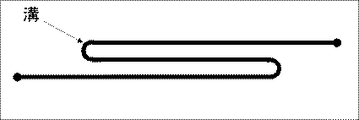
1)一方のアクリル板を機械加工し、図1に示した形状の溝を形成した。溝の寸法は、幅500μm、深さ200μm、電極にかかる長さは100mmであった。溝の両端に外部から送液するための穴を空けた。 1) One acrylic plate was machined to form a groove having the shape shown in FIG. The dimensions of the groove were a width of 500 μm, a depth of 200 μm, and a length applied to the electrode of 100 mm. Holes for feeding liquid from the outside were made at both ends of the groove.
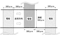
2)もう一方のアクリル板に、図2に示した電極形状をくり貫いたマスクを被せて、クロムを1000Å蒸着してから、金を2000Å蒸着し電極を設けた。電極の寸法は幅300μm、長さ10mmであり、作用極と対極用にそれぞれ25本を交互に配置し、各電極の間隙を300μmであった。 2) The other acrylic plate was covered with a mask in which the electrode shape shown in FIG. 2 was cut, and chrome was deposited by 1000 liters, and then gold was deposited by 2,000 liters to provide an electrode. The electrodes had a width of 300 μm and a length of 10 mm. 25 electrodes were alternately arranged for the working electrode and the counter electrode, and the gap between the electrodes was 300 μm.
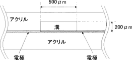
3)上記の2枚のアクリル板を圧着させ、115℃に設定したイナートオーブンに1時間入れ、熱圧着させマイクロリアクターを完成させた。マイクロリアクターの概略平面図を図3に、電極部分の部分断面概略図と部分平面概略図をそれぞれ図4と図5に示した。 3) The above-mentioned two acrylic plates were pressure-bonded, placed in an inert oven set at 115 ° C. for 1 hour, and thermocompression bonded to complete the microreactor. A schematic plan view of the microreactor is shown in FIG. 3, and a partial cross-sectional schematic view and a partial plan schematic view of the electrode portion are shown in FIGS. 4 and 5, respectively.
マイクロリアクターの注入口から反応液(マレイン酸ジメチル:5 wt%,酢酸ナトリウム:2wt%/メタノール)を、シリンジポンプを用いて10μL/minの流量で送液した。マイクロリアクターは、ペルチェ素子の上に載せ、ペルチェ素子温度を15℃に制御した。この時の、電極上の滞留時間は、約60秒であった。直流電源(菊水社製 PMC250)を使い、1mAの定電流条件で、電気化学反応を実施した。この時の電圧は、6.5Vであった。吐出したサンプルは、ガスクロマトグラフィーで定量分析した。マレイン酸ジメチルの二量体であるテトラブチルブタンカルボン酸の収率は4.9mol%、選択率は9.1mol%であった。原料と支持電解質が反応した副生成物は、生成しなかった。 A reaction solution (dimethyl maleate: 5 wt%, sodium acetate: 2 wt% / methanol) was fed from the injection port of the microreactor at a flow rate of 10 μL / min using a syringe pump. The microreactor was placed on the Peltier element and the temperature of the Peltier element was controlled at 15 ° C. At this time, the residence time on the electrode was about 60 seconds. An electrochemical reaction was performed using a DC power source (PMC250 manufactured by Kikusui Co., Ltd.) under a constant current condition of 1 mA. The voltage at this time was 6.5V. The discharged sample was quantitatively analyzed by gas chromatography. The yield of tetrabutylbutanecarboxylic acid, which is a dimer of dimethyl maleate, was 4.9 mol%, and the selectivity was 9.1 mol%. A by-product in which the raw material and the supporting electrolyte reacted was not generated.
(比較例1)
マイクロリアクターは、作用極と対極を流路に対し平行に設けた以外は、実施例1と同様にして作製した。溝の寸法は、幅900μm、深さ200μm、電極にかかる長さは100mmとし、また両電極の幅は300μm、電極間距離は300μmとし、電極部分の部分断面概略図と部分平面概略図をそれぞれ図6と図7に示した。
(Comparative Example 1)
The microreactor was produced in the same manner as in Example 1 except that the working electrode and the counter electrode were provided in parallel to the flow path. The dimensions of the groove are a width of 900 μm, a depth of 200 μm, a length of the electrode of 100 mm, a width of both electrodes of 300 μm, and a distance between the electrodes of 300 μm. This is shown in FIG. 6 and FIG.
実施例1と同様の条件で、電気化学反応を実施した。この時の電圧は、6.5Vであった。マレイン酸ジメチルの二量体であるテトラブチルブタンカルボン酸の収率は、0.5mol%、選択率は2.5mol%であった。原料と支持電解質が反応した副生成物の収率は、50%であった。 The electrochemical reaction was carried out under the same conditions as in Example 1. The voltage at this time was 6.5V. The yield of tetrabutylbutanecarboxylic acid, which is a dimer of dimethyl maleate, was 0.5 mol%, and the selectivity was 2.5 mol%. The yield of the byproduct resulting from the reaction between the raw material and the supporting electrolyte was 50%.
Claims (6)
Priority Applications (1)
| Application Number | Priority Date | Filing Date | Title |
|---|---|---|---|
| JP2005108460A JP2006281175A (en) | 2005-04-05 | 2005-04-05 | Electrochemical microreactor and manufacturing method using the same |
Applications Claiming Priority (1)
| Application Number | Priority Date | Filing Date | Title |
|---|---|---|---|
| JP2005108460A JP2006281175A (en) | 2005-04-05 | 2005-04-05 | Electrochemical microreactor and manufacturing method using the same |
Publications (1)
| Publication Number | Publication Date |
|---|---|
| JP2006281175A true JP2006281175A (en) | 2006-10-19 |
Family
ID=37403627
Family Applications (1)
| Application Number | Title | Priority Date | Filing Date |
|---|---|---|---|
| JP2005108460A Pending JP2006281175A (en) | 2005-04-05 | 2005-04-05 | Electrochemical microreactor and manufacturing method using the same |
Country Status (1)
| Country | Link |
|---|---|
| JP (1) | JP2006281175A (en) |
Cited By (2)
| Publication number | Priority date | Publication date | Assignee | Title |
|---|---|---|---|---|
| JP2008096235A (en) * | 2006-10-11 | 2008-04-24 | Sharp Corp | Electrochemical measurement microchip |
| CN108622986A (en) * | 2018-05-15 | 2018-10-09 | 宁波合信节能环保科技有限公司 | A kind of waveform electrochemistry sewage disposal system |
Citations (4)
| Publication number | Priority date | Publication date | Assignee | Title |
|---|---|---|---|---|
| JPH05322832A (en) * | 1992-05-22 | 1993-12-07 | Nippon Telegr & Teleph Corp <Ntt> | Thin-layer electrochemical detector |
| JPH09243590A (en) * | 1996-03-08 | 1997-09-19 | Tdk Corp | Micro comb-shaped electrode and its manufacture and electrode unit for electrochemical measurement of solution system |
| JP2003172736A (en) * | 2001-12-07 | 2003-06-20 | Toyo Kohan Co Ltd | Microchip for chemical reaction |
| JP2004514786A (en) * | 2000-11-22 | 2004-05-20 | ビーエーエスエフ アクチェンゲゼルシャフト | Preparation of butanetetracarboxylic acid derivatives by coupled electrosynthesis |
-
2005
- 2005-04-05 JP JP2005108460A patent/JP2006281175A/en active Pending
Patent Citations (4)
| Publication number | Priority date | Publication date | Assignee | Title |
|---|---|---|---|---|
| JPH05322832A (en) * | 1992-05-22 | 1993-12-07 | Nippon Telegr & Teleph Corp <Ntt> | Thin-layer electrochemical detector |
| JPH09243590A (en) * | 1996-03-08 | 1997-09-19 | Tdk Corp | Micro comb-shaped electrode and its manufacture and electrode unit for electrochemical measurement of solution system |
| JP2004514786A (en) * | 2000-11-22 | 2004-05-20 | ビーエーエスエフ アクチェンゲゼルシャフト | Preparation of butanetetracarboxylic acid derivatives by coupled electrosynthesis |
| JP2003172736A (en) * | 2001-12-07 | 2003-06-20 | Toyo Kohan Co Ltd | Microchip for chemical reaction |
Cited By (2)
| Publication number | Priority date | Publication date | Assignee | Title |
|---|---|---|---|---|
| JP2008096235A (en) * | 2006-10-11 | 2008-04-24 | Sharp Corp | Electrochemical measurement microchip |
| CN108622986A (en) * | 2018-05-15 | 2018-10-09 | 宁波合信节能环保科技有限公司 | A kind of waveform electrochemistry sewage disposal system |
Similar Documents
| Publication | Publication Date | Title |
|---|---|---|
| Atobe et al. | Applications of flow microreactors in electrosynthetic processes | |
| Regnier et al. | Enhancing electrochemical reactions in organic synthesis: the impact of flow chemistry | |
| Hardwick et al. | Advances in electro-and sono-microreactors for chemical synthesis | |
| US6878255B1 (en) | Microfluidic devices with thick-film electrochemical detection | |
| Haswell et al. | The application of micro reactors to synthetic chemistry | |
| Brivio et al. | Miniaturized continuous flow reaction vessels: influence on chemical reactions | |
| Ziogas et al. | Electrochemical microstructured reactors: design and application in organic synthesis | |
| Green et al. | A microflow electrolysis cell for laboratory synthesis on the multigram scale | |
| Löwe et al. | State-of-the-art in microreaction technology: concepts, manufacturing and applications | |
| Nagaki et al. | Design of a numbering-up system of monolithic microreactors and its application to synthesis of a key intermediate of valsartan | |
| Zhu et al. | Integrated droplet analysis system with electrospray ionization-mass spectrometry using a hydrophilic tongue-based droplet extraction interface | |
| Arai et al. | An anodic aromatic C, C cross-coupling reaction using parallel laminar flow mode in a flow microreactor | |
| van den Brink et al. | Miniaturization of electrochemical cells for mass spectrometry | |
| US20210253452A1 (en) | Electrochemical flow reactor | |
| EP0871545A4 (en) | SILICONE-BASED SHEATHING DEVICES FOR CHEMICAL REACTIONS | |
| WO2013027393A1 (en) | Micro fluid device | |
| Shida et al. | Electrosynthesis in laminar flow using a flow microreactor | |
| Kucherov et al. | Development of 3D+ G printing for the design of customizable flow reactors | |
| Makarshin et al. | Microchannel systems for fine organic synthesis | |
| EP2204233A1 (en) | Flow cell, apparatus for concentrating radioactive fluorine anion, and method of concentrating radioactive fluorine anion | |
| Stergiou et al. | Electrochemical reduction of nitrobenzene via redox-mediated chronoamperometry | |
| JP4783598B2 (en) | Manufacturing method of chemical substances | |
| Yoshida | Organic electrochemistry, microreactors, and their synergy | |
| JP2006281175A (en) | Electrochemical microreactor and manufacturing method using the same | |
| JP2006225726A (en) | Method for producing chemical substance by electrochemical reaction |
Legal Events
| Date | Code | Title | Description |
|---|---|---|---|
| A621 | Written request for application examination |
Free format text: JAPANESE INTERMEDIATE CODE: A621 Effective date: 20070709 |
|
| RD03 | Notification of appointment of power of attorney |
Free format text: JAPANESE INTERMEDIATE CODE: A7423 Effective date: 20080404 |
|
| A977 | Report on retrieval |
Free format text: JAPANESE INTERMEDIATE CODE: A971007 Effective date: 20090522 |
|
| A131 | Notification of reasons for refusal |
Free format text: JAPANESE INTERMEDIATE CODE: A131 Effective date: 20090602 |
|
| A521 | Written amendment |
Free format text: JAPANESE INTERMEDIATE CODE: A523 Effective date: 20090731 |
|
| A02 | Decision of refusal |
Free format text: JAPANESE INTERMEDIATE CODE: A02 Effective date: 20100817 |