JP2006281402A - Method and apparatus for judging condition of grinding operation, and method for controlling grinding operation - Google Patents
Method and apparatus for judging condition of grinding operation, and method for controlling grinding operation Download PDFInfo
- Publication number
- JP2006281402A JP2006281402A JP2005107070A JP2005107070A JP2006281402A JP 2006281402 A JP2006281402 A JP 2006281402A JP 2005107070 A JP2005107070 A JP 2005107070A JP 2005107070 A JP2005107070 A JP 2005107070A JP 2006281402 A JP2006281402 A JP 2006281402A
- Authority
- JP
- Japan
- Prior art keywords
- grinding
- state
- sensor
- detected
- work
- Prior art date
- Legal status (The legal status is an assumption and is not a legal conclusion. Google has not performed a legal analysis and makes no representation as to the accuracy of the status listed.)
- Pending
Links
- 238000000034 method Methods 0.000 title claims abstract description 45
- 238000004458 analytical method Methods 0.000 claims description 23
- 238000005520 cutting process Methods 0.000 claims description 20
- 238000009826 distribution Methods 0.000 claims description 18
- 230000005856 abnormality Effects 0.000 claims description 12
- 230000002159 abnormal effect Effects 0.000 claims description 3
- 238000005259 measurement Methods 0.000 claims description 2
- 238000001514 detection method Methods 0.000 description 8
- 230000003044 adaptive effect Effects 0.000 description 6
- 239000006061 abrasive grain Substances 0.000 description 4
- 230000005540 biological transmission Effects 0.000 description 4
- 230000008859 change Effects 0.000 description 4
- 238000005516 engineering process Methods 0.000 description 4
- 238000012544 monitoring process Methods 0.000 description 4
- 238000005498 polishing Methods 0.000 description 4
- 238000011160 research Methods 0.000 description 4
- 230000008054 signal transmission Effects 0.000 description 4
- 238000004364 calculation method Methods 0.000 description 3
- 238000010586 diagram Methods 0.000 description 3
- 230000000694 effects Effects 0.000 description 3
- 238000003754 machining Methods 0.000 description 3
- 230000007246 mechanism Effects 0.000 description 3
- 230000002093 peripheral effect Effects 0.000 description 3
- 230000002238 attenuated effect Effects 0.000 description 2
- 239000000470 constituent Substances 0.000 description 2
- 238000011161 development Methods 0.000 description 2
- 238000004519 manufacturing process Methods 0.000 description 2
- 230000001052 transient effect Effects 0.000 description 2
- 238000012935 Averaging Methods 0.000 description 1
- 230000009471 action Effects 0.000 description 1
- 230000008901 benefit Effects 0.000 description 1
- 239000011230 binding agent Substances 0.000 description 1
- 238000005336 cracking Methods 0.000 description 1
- 230000007547 defect Effects 0.000 description 1
- 230000002950 deficient Effects 0.000 description 1
- 238000011156 evaluation Methods 0.000 description 1
- 238000010438 heat treatment Methods 0.000 description 1
- 230000001771 impaired effect Effects 0.000 description 1
- 238000012423 maintenance Methods 0.000 description 1
- 239000000463 material Substances 0.000 description 1
- 239000011148 porous material Substances 0.000 description 1
- 230000002028 premature Effects 0.000 description 1
- 230000002265 prevention Effects 0.000 description 1
- 230000008569 process Effects 0.000 description 1
- 238000012545 processing Methods 0.000 description 1
- 230000002250 progressing effect Effects 0.000 description 1
- 230000004044 response Effects 0.000 description 1
- 230000004043 responsiveness Effects 0.000 description 1
- 238000004904 shortening Methods 0.000 description 1
- 239000007787 solid Substances 0.000 description 1
- 239000011343 solid material Substances 0.000 description 1
- 230000000087 stabilizing effect Effects 0.000 description 1
- 230000007704 transition Effects 0.000 description 1
- 230000007723 transport mechanism Effects 0.000 description 1
Images


Landscapes
- Constituent Portions Of Griding Lathes, Driving, Sensing And Control (AREA)
- Grinding Of Cylindrical And Plane Surfaces (AREA)
Abstract
Description
本発明は、研削作業が正常に進行しているか否かを自動的に判定し、適正に管理するための判定方法および同装置にするものである。
上記の判定結果の信号を研削機器にフィードバックすることにより、研削作業状態を自動的に制御し、とりわけ研削力を定常化して高い加工精度を保つことができる。
The present invention automatically determines whether or not a grinding operation is proceeding normally, and provides a determination method and apparatus for appropriately managing the grinding operation.
By feeding back the signal of the above determination result to the grinding machine, it is possible to automatically control the grinding operation state, in particular, to stabilize the grinding force and maintain high machining accuracy.
最近の研削盤は高度に自動化されているので、一人の作業員が多数の研削盤を監視・管理しなければならない。
このため、研削作業が異状無く良好な状態で進行しているか否かを自動的に判定する技術が必要とされる。
良好な研削作業を遂行するには、次に説明するように積極的な面の管理と消極的な面の管理との両方が必要である。
すなわち、積極的な面では適応制御研削を図り、消極的な面では部材損傷の未然防止を図らねばならない。
Since modern grinders are highly automated, a single worker must monitor and manage a large number of grinders.
For this reason, the technique which determines automatically whether the grinding operation is progressing in a good state without any abnormality is required.
Performing a good grinding operation requires both active and passive surface management, as described below.
That is, adaptive control grinding must be performed on the positive side, and damage to the member must be prevented on the negative side.
前記の適応制御研削について考察する。
研削作業において重要な管理項目の一つに、研削砥石の切込み速度が有る。ところが、砥石軸系の剛性の関係から、設定切込み速度に対する被加工物の寸法変化の応答性が良くない場合がある。
このため応答の過渡的状態が発生し、この過渡時間が秒単位に及ぶことも珍しくない。
過渡時間の短縮と精度安定とを目的として、研削抵抗を直接あるいは間接的に検出し、この検出値に基づいて切込み操作を制御する方法を適応制御研削という。
適応研削の一つの方式として、切込み台を一定の油圧で送り駆動する定圧力研削(CF研削)が広く知られている。
また、砥石軸を送り駆動するモータの消費電力を検出して、該電力を一定に保持するように切込み台を制御する方法を定電力研削といい、これも広く知られている。
Consider the adaptive control grinding.
One of the important management items in grinding work is the cutting speed of the grinding wheel. However, due to the rigidity of the grindstone shaft system, the responsiveness of the dimensional change of the workpiece to the set cutting speed may not be good.
For this reason, a transient state of response occurs, and it is not uncommon for this transient time to be in seconds.
For the purpose of shortening the transition time and stabilizing the accuracy, a method of directly or indirectly detecting the grinding resistance and controlling the cutting operation based on the detected value is called adaptive control grinding.
As one method of adaptive grinding, constant pressure grinding (CF grinding) in which a cutting table is fed and driven at a constant hydraulic pressure is widely known.
A method of detecting the power consumption of the motor that feeds and drives the grinding wheel shaft and controlling the cutting table so as to keep the power constant is called constant power grinding, which is also widely known.
次に、部材損傷の未然防止について考察すると、研削機における重要な損耗部材は研削砥石である。
研削機に万一の故障が発生したり、調整状態が狂ったりしたときは、即時に発見して対処しなければならないのは勿論であるが、別段の故障を発生しなくても、研削砥石は使用に伴って損耗する。
損耗した砥石で研削作業を行なうと、作業能率が悪くなるのみでなく、研削仕上げ面の品質が低下する。このため、研削砥石が損耗したならば適時にドレッシングし、または新品と交換しなければならない。
上記のドレッシングまたは交換は、適時であることが大切である。遅すぎると、製品の品質を損じるが、さりとて早きに失すると却って作業能率を低下させ、加工コストを増加させてしまう。
ところが研削砥石の損耗は、その形態が複雑である上に、その進行速度に影響する要因が多いので、ドレッシング(または交換)の時機判定が難しい。
Next, considering the prevention of member damage, an important wear member in a grinding machine is a grinding wheel.
In the unlikely event that a grinding machine breaks down or goes out of adjustment, it must be detected immediately and dealt with, but even if no other trouble occurs, the grinding wheel Wears with use.
When the grinding operation is performed with the worn grindstone, not only the work efficiency is deteriorated, but also the quality of the ground surface is deteriorated. For this reason, if the grinding wheel is worn out, it must be dressed in a timely manner or replaced with a new one.
It is important that the dressing or replacement described above is timely. If it is too late, the quality of the product is impaired, but if it is lost too quickly, the work efficiency is lowered and the processing cost is increased.
However, the wear of a grinding wheel is complicated in form and has many factors that affect its traveling speed. Therefore, it is difficult to determine the timing of dressing (or replacement).
研削砥石の損耗態様を大別すると次の三つになる。
イ.目づまり…砥石の気孔に、切子などの異物が詰まった状態。
ロ.目つぶれ…砥粒の角が磨り減って丸くなった状態。
ハ.目こぼれ…バインダのブリッジが壊れて砥粒が脱落した状態。
これらの損耗形態は複合して発生し、進行する場合が少なくない。
損耗の進行は研削作業条件によって著しく異なり、理論的計算によって算出することは
一般に不可能である。つまり、実績データを参照して推測する他に、実用的な手段は知られていなかった。
消極的な観点から「微小な異常を即時かつ自動的に判定する」という技術は、積極的に「判定信号をフィードバックして最良の状態で研削作業を遂行する」ことに繋がる。
本発明において、「微小異常の自動的判定」と「高精度の維持」とは、技術的思想として表裏一体を為すものである。
The wear modes of the grinding wheel are roughly divided into the following three.
I. Clogged: The grindstone is clogged with foreign objects such as facets.
B. Clogged ... A state where the corners of the abrasive grains are worn down and rounded.
C. Spilling ... Binder bridge is broken and abrasive grains fall off.
These forms of wear often occur in combination and progress.
The progress of wear varies significantly depending on the grinding work conditions and is generally impossible to calculate by theoretical calculation. In other words, there is no known practical means other than inferring with reference to the result data.
From a passive point of view, the technique of “determining minute abnormality immediately and automatically” leads to “feedback of a decision signal to perform grinding work in the best state”.
In the present invention, “automatic determination of minute abnormality” and “maintenance of high accuracy” are the two sides of the technical idea.
砥石の損耗状態を間接的に推測する技術として、特開昭63−174872号公報、および特開平7−171742号公報が提案されている。これらの技術は、研削反力を電動機負荷として検出するものである。
これらは、10年昔においては新規性,進歩性を有する新鋭の技術であり、研削機械産業の発展に寄与するところ多大であった。しかし今日、惜しむらくはIT革命に取り残されて陳腐化したことを否めない。
JP-A-63-174872 and JP-A-7-171742 have been proposed as techniques for indirectly estimating the wear state of a grindstone. These techniques detect a grinding reaction force as a motor load.
Ten years ago, these were new and innovative technologies that greatly contributed to the development of the grinding machine industry. Today, however, I cannot deny that Ishimura was left out of the IT revolution and became obsolete.
砥石の損耗ではなく、切削工具(例えばドリル)の損耗を検出する手段として超音波を利用しようという研究も、非特許文献1に示したように為されている。この技術はドリルユニットにAEセンサを装着している。
上記のAEとはAcoustic Emissionの略であって、AEセンサとは、
固体材料が微視的な損傷を生じたり、該微視的な損傷が成長する際に発生する超音波を受信する検出器をいう。
上記の研究において、ドリルの折損をAEセンサで検出できた旨が報告されている。
The above AE is an abbreviation of Acoustic Emission, and the AE sensor is
A detector that receives ultrasonic waves generated when a solid material causes microscopic damage or grows.
In the above research, it has been reported that breakage of a drill can be detected by an AE sensor.
本発明は以上に述べた事情に鑑みて為されたものであって、その目的とするところは、研削作業の状態電子技術的に検出して、作業員に別段の知識や熟練を要せず、研削作業の状態を自動的に監視・管理して異状発生に即応することができ、さらに、研削砥石のドレッシング(交換)時期を正確に判定し得る方法、および同装置、並びに、上記の判定を自動的にフイードバックして高い加工精度を維持するように制御する技術を提供するにある。 The present invention has been made in view of the above-described circumstances, and the object of the present invention is to detect the state of grinding work electronically without requiring any additional knowledge or skill for the worker. , A method capable of automatically monitoring and managing the state of the grinding operation to immediately respond to the occurrence of an abnormality, and accurately determining the dressing (replacement) timing of the grinding wheel, the same apparatus, and the above determination Therefore, it is necessary to provide a technology for automatically feeding back and controlling so as to maintain high machining accuracy.
次に本発明の基本的な原理を、その1実施形態に対応する図1を参照して略述すると、
円柱面を有するワーク1が、その外周面を2個のロール2,3と1個のシュー4とによって無心的に支持され、図に現れていない駆動手段によってZ軸周りに回転駆動されている。符号5は、砥石車である研削砥石であって、前記ワーク1の内周面を研削加工する。
従来、この研削砥石5から発生する各種の振動(可聴音波及び超音波を含む)を検出して該研削砥石の状態を検出しようと試みられたが、回転に伴う雑音が入るので、正確な判定が困難であった。
本発明は、回転雑音が入らないように、静止部材であるシュー4に、AEセンサ6を装着して「研削音」を検出する。詳しくは、研削音の内の超音波成分を検出して解析する。
図1と異なる実施形態(後掲の図3)として、シューに代えてブレードにAEセンサを装着することもできる。これらを総合して本発明の特徴は、AEセンサを回転部材に装着せず(直接,間接を問わず、回転部材には装着しないで)、静止部材に装着する。
詳しくは、被加工物に摺動接触してこれを支持している静止部材にAEセンサを装着する。静止部材の名称は、シューであっても、ブレードであっても、ストッパであっても、ガイドであっても、何であってもよい。
Next, the basic principle of the present invention will be briefly described with reference to FIG. 1 corresponding to one embodiment thereof.
A
Conventionally, an attempt has been made to detect the state of the grinding wheel by detecting various vibrations (including audible sound waves and ultrasonic waves) generated from the grinding wheel 5. It was difficult.
In the present invention, the AE sensor 6 is attached to the shoe 4 that is a stationary member to detect “grinding sound” so that rotational noise does not enter. Specifically, the ultrasonic component in the grinding sound is detected and analyzed.
As an embodiment different from FIG. 1 (FIG. 3 described later), an AE sensor can be attached to the blade instead of the shoe. By combining these, the feature of the present invention is that the AE sensor is not attached to the rotating member (directly or indirectly, not attached to the rotating member), but is attached to the stationary member.
Specifically, the AE sensor is mounted on a stationary member that is in sliding contact with and supports the workpiece. The name of the stationary member may be a shoe, a blade, a stopper, a guide, or anything.
以上に述べた原理に基づく具体的な構成として請求項1に係る発明装置の構成は、(図1参照)円柱面を有するワーク(1)の外周を、回転部材であるロール(2,3)と、静止部材であるシュー(4)とによって無心的に支持し、上記ワークに研削砥石(5)を接触させて研削する内面研削盤において、
上記のシューにAEセンサ(6)が装着されていて、研削によって放射される超音波振動を電気信号として検出し得るようになっており、
かつ、検出した電気信号を解析して、研削作業に異状発生の有無、研削ステップの進捗状態、及び研削砥石の損耗状態の少なくとも何れか一つを判定する演算回路を備えていることを特徴とする。
As a specific configuration based on the principle described above, the configuration of the invention device according to claim 1 (see FIG. 1) is that the outer periphery of the work (1) having a cylindrical surface is a roll (2, 3) that is a rotating member. And an inner surface grinding machine that supports the workpiece (4), which is a stationary member, and grinds the workpiece by bringing the grinding wheel (5) into contact with the workpiece.
An AE sensor (6) is attached to the shoe, and ultrasonic vibrations radiated by grinding can be detected as an electrical signal.
And an arithmetic circuit that analyzes the detected electrical signal and determines at least one of the occurrence of abnormality in the grinding operation, the progress state of the grinding step, and the wear state of the grinding wheel. To do.
以上に説明した請求項1の発明装置は内面研削盤に適用され、研削音がAEセンサで検出される。
研削音は研削作業の状態によって種々に変化し、例えば研削砥石の損耗状態によっても変化するので、これを利用して研削作業の状態、特に研削砥石の損耗状態を正確に判定することができる。
しかも、AEセンサが「静止部材であるシュー」に装着されているので、回転雑音の混入が少なく、電気的信号の伝送が容易である(回転部材から電気的信号を取り出そうとすると、電線が捩れないよう、ワイヤレスにしなければならない。このため構造が複雑となり、信号の減衰が多大で、コスト高になる)。
上述のごとく本発明装置を適用すると、研削状態をAE監視することによって、適応制御研削におけると同様な効果を奏する。
The above-described inventive device of
The grinding sound changes variously depending on the state of the grinding operation, and also changes depending on, for example, the wear state of the grinding wheel. Therefore, it is possible to accurately determine the state of the grinding operation, particularly the wear state of the grinding wheel.
Moreover, since the AE sensor is mounted on the “shoe, which is a stationary member”, there is little mixing of rotational noise, and transmission of electrical signals is easy (when an electrical signal is extracted from the rotating member, the electric wire is twisted). It has to be wireless so that there is no need for it, which complicates the structure, greatly attenuates the signal and increases the cost).
As described above, when the device of the present invention is applied, the same effect as in adaptive control grinding can be obtained by AE monitoring of the grinding state.
請求項2に係る発明装置の構成は、(図3参照) 円柱面を有するワーク(1)の外周を、回転部材である調整砥石(9)と、静止部材であるブレード(10)とによって無心的に支持し、上記ワークに研削砥石(11)を接触させて研削する方式のセンタレス研削機において、
上記のブレードにAEセンサ(6)が装着されていて、研削によって放射される超音波振動を電気信号として検出し得るようになっており、
かつ、検出した電気信号を解析して、研削作業に異状発生の有無、研削ステップの進捗状態、及び研削砥石の損耗状態を判定する演算回路を備えていることを特徴とする。
The configuration of the invention apparatus according to claim 2 is as follows (see FIG. 3). The outer periphery of the work (1) having a cylindrical surface is centered by an adjusting grindstone (9) as a rotating member and a blade (10) as a stationary member. In a centerless grinding machine of a system for grinding by bringing the grinding wheel (11) into contact with the workpiece and grinding the workpiece,
An AE sensor (6) is mounted on the blade, and can detect ultrasonic vibrations radiated by grinding as an electrical signal.
An arithmetic circuit is provided that analyzes the detected electrical signal and determines whether or not abnormality has occurred in the grinding operation, the progress state of the grinding step, and the wear state of the grinding wheel.
以上に説明した請求項2の発明装置はセンタレス研削機に適用され、研削音がAEセンサで検出される。
研削音は研削作業状態によって種々に変化し、特に研削砥石の損耗状態によって変化するので、これを利用して研削作業状態を正確に判定することができる。
しかも、AEセンサが「静止部材であるブレード」に装着されているので、回転雑音の混入が少なく、電気的信号の伝送が容易である(回転部材から電気的信号を取り出そうとすると、電線が捩れないよう、ワイヤレスにしなければならない。このため構造複雑、減衰多大、コスト高になる)。
The invention apparatus of claim 2 described above is applied to a centerless grinding machine, and a grinding sound is detected by an AE sensor.
The grinding sound changes variously depending on the grinding operation state, and particularly changes depending on the wear state of the grinding wheel, so that it is possible to accurately determine the grinding operation state.
Moreover, since the AE sensor is mounted on the “blade that is a stationary member”, there is little mixing of rotational noise, and transmission of electrical signals is easy (when an electrical signal is extracted from the rotating member, the wire is twisted). It must be wireless so that it is not complicated, which leads to structural complexity, significant attenuation, and high cost).
請求項3に係る発明装置の構成は、前記請求項1または請求項2の発明装置の構成要件に加えて、前記の演算回路が、波高レベル解析回路(12)と砥石損耗度判定回路(14)とを有しており、
かつ、上記判定回路は、特定の周波数範囲の超音波波高を閾値と比較する機能を有するものであることを特徴とする。
According to a third aspect of the present invention, in addition to the configuration requirements of the first or second aspect of the present invention, the arithmetic circuit includes a wave height level analysis circuit (12) and a grindstone wear degree determination circuit (14). ) And
In addition, the determination circuit has a function of comparing the ultrasonic wave height in a specific frequency range with a threshold value.
以上に説明した請求項3の発明装置によると、研削状態に異状を発生したり研削砥石の損耗が進行したりすると超音波波高が大きくなる現象を利用して、予め設定された閾値と比較することにより、作業員に別段の知識や熟練を要せず、迅速に、かつ正確に、研削作業の状態を判定して、適正な時機に研削砥石のドレッシング(交換)を行なうことができる。 According to the invention device of the third aspect described above, the phenomenon is compared with a preset threshold value by utilizing the phenomenon that the ultrasonic wave height increases when the grinding state becomes abnormal or the grinding wheel wears out. Accordingly, it is possible to quickly and accurately determine the state of the grinding operation and perform dressing (replacement) of the grinding wheel at an appropriate time without requiring any special knowledge or skill for the worker.
請求項4に係る発明装置の構成は、前記請求項1または請求項2の発明装置の構成要件に加えて、
前記の演算回路が、周波数解析回路(13)と砥石損耗度判定回路(14)とを有しており、
かつ、上記判定回路は、「損耗した砥石が放射する超音波の周波数分布特性」を記憶していて、「解析回路から出力された周波数分布状態」を上記の「記憶している周波数分布特性」と比較する機能を有するものであることを特徴とする。
The configuration of the inventive device according to claim 4 is in addition to the configuration requirements of the inventive device according to
The arithmetic circuit includes a frequency analysis circuit (13) and a grindstone wear degree determination circuit (14).
In addition, the determination circuit stores “frequency distribution characteristics of ultrasonic waves emitted from a worn grindstone”, and “stores frequency distribution characteristics output from the analysis circuit” as described above. It has the function to compare with.
以上に説明した請求項4の発明装置によると、研削砥石の損耗が進行すると超音波の周波数分布が変化する現象を利用して、予め設定された周波数分布形態と比較することにより、作業員に別段の知識や熟練を要せず、迅速に、かつ正確に、研削作業の状態を判定して、適正な時機に研削砥石のドレッシング(交換)を行なうことができる。 According to the invention device of claim 4 described above, by using the phenomenon that the frequency distribution of the ultrasonic waves changes as the grinding wheel wears out, the frequency distribution form of ultrasonic waves is compared with a preset frequency distribution form. It is possible to quickly and accurately determine the state of the grinding operation and perform dressing (replacement) of the grinding wheel at an appropriate time without requiring any special knowledge or skill.
請求項5に係る発明方法の構成は、(図1参照)円柱面を有するワーク(1)の外周を、回転部材であるロール(2,3)と、静止部材であるシュー(4)とによって無心的に支持し、上記ワークに研削砥石(5)を接触させて研削する方式の内面研削盤において、
上記のシューにAEセンサ(6)を装着しておき、
研削によって放射される超音波振動を上記AEセンサ6により電気信号として検出し、
検出した電気信号を解析して、前記研削作業の状態を判定することを特徴とする。
The configuration of the invention method according to claim 5 (see FIG. 1) is that the outer periphery of the work (1) having a cylindrical surface is formed by a roll (2, 3) as a rotating member and a shoe (4) as a stationary member. In an internal grinding machine of a method of supporting involuntarily and grinding by bringing the grinding wheel (5) into contact with the workpiece,
The AE sensor (6) is attached to the above shoe,
The ultrasonic vibration emitted by grinding is detected as an electrical signal by the AE sensor 6;
The detected electrical signal is analyzed to determine the state of the grinding operation.
以上に説明した請求項5の発明方法は内面研削盤に適用され、研削音をAEセンサで検出する。
研削音は研削作業の異常発生や研削砥石の損耗進行によって変化するので、これを利用して研削作業の状態を正確に判定することができる。
しかも、AEセンサを「静止部材であるシュー」に装着するので、回転雑音の混入が少なく、電気的信号の伝送が容易である(センサを回転部材に装着すると、電気的信号の取り出しが非常に厄介である)。
すなわち、本請求項5の発明方法を適用してAEセンサをシューに装着すると、該AEセンサから解析回路までを有線で接続しても捩れないので、簡単で安価な部材を用いて、電気信号をほとんど減衰させずに伝送することができる。
以上に述べたように、本発明方法を適用すると、研削音をAE監視することにより、適応制御研削におけると同様な効果が得られる。
The above-described invention method according to claim 5 is applied to an internal grinding machine, and a grinding sound is detected by an AE sensor.
Since the grinding sound changes depending on the occurrence of abnormality in the grinding work or the progress of wear of the grinding wheel, the state of the grinding work can be accurately determined using this.
In addition, since the AE sensor is attached to the “shoe as a stationary member”, there is little mixing of rotational noise, and electrical signals can be transmitted easily. Awkward).
That is, when the AE sensor is attached to the shoe by applying the method of the present invention, the electric signal is not twisted even if the connection from the AE sensor to the analysis circuit is wired. Can be transmitted with little attenuation.
As described above, when the method of the present invention is applied, the same effect as in adaptive control grinding can be obtained by AE monitoring of the grinding sound.
請求項6に係る発明方法の構成は、(図3参照)円柱面を有するワーク(1)の外周を、回転部材である調整砥石(9)と、静止部材であるブレード(10)とによって無心的に支持し、上記ワークに研削砥石(11)を接触させて研削するセンタレス研削機において、 上記のブレードにAEセンサ(6)を装着しておき、
研削によって放射される超音波振動を上記AEセンサ6により電気信号として検出し、
検出した電気信号を解析して、前記研削作業の状態を判定することを特徴とする。
The configuration of the inventive method according to claim 6 (see FIG. 3) is that the outer periphery of the work (1) having a cylindrical surface is insensitive by an adjusting grindstone (9) as a rotating member and a blade (10) as a stationary member. In a centerless grinding machine for grinding by bringing a grinding wheel (11) into contact with the workpiece and mounting the AE sensor (6) on the blade,
The ultrasonic vibration emitted by grinding is detected as an electrical signal by the AE sensor 6;
The detected electrical signal is analyzed to determine the state of the grinding operation.
以上に説明した請求項6の発明方法はセンタレス研削機に適用され、研削音をAEセンサで検出する。
研削音は研削作業の状態や削砥石の損耗によって変化するので、これを利用して研削作業の状態を正確に判定することができる。
しかも、AEセンサを「静止部材であるブレード」に装着するので、回転雑音の混入が少なく、電気的信号の伝送が容易である(センサを回転部材に装着すると、電気的信号の取り出しが非常に厄介である)。
すなわち、本請求項6の発明方法を適用してAEセンサをブレードに装着すると、該AEセンサから解析回路までを有線で接続しても捩れないので、簡単で安価な部材を用いて、電気信号をほとんど減衰させずに伝送することができる。
The above-described method of the present invention according to claim 6 is applied to a centerless grinding machine, and a grinding sound is detected by an AE sensor.
Since the grinding sound changes depending on the state of the grinding operation and the wear of the grinding wheel, the state of the grinding operation can be accurately determined using this.
Moreover, since the AE sensor is mounted on the “blade that is a stationary member”, there is little mixing of rotational noise and electrical signal transmission is easy (when the sensor is mounted on the rotating member, the electrical signal can be taken out very much). Awkward).
That is, when the AE sensor is mounted on the blade by applying the inventive method of claim 6, since it does not twist even if the connection from the AE sensor to the analysis circuit is wired, an electrical signal can be obtained using a simple and inexpensive member. Can be transmitted with little attenuation.
請求項7に係る発明方法の構成は、前記請求項5または請求項6の発明方法の構成要件に加えて、研削砥石が放射する超音波の波高レベルを、損耗の程度に対応させて予め実測しておき、
検出された超音波の波高を、上記の実測値と比較して損耗状態を判定することを特徴とする。
In addition to the constituent features of the method of the invention of claim 5 or claim 6, the configuration of the method of the invention of claim 7 is preliminarily measured in accordance with the level of ultrasonic wave radiated by the grinding wheel in accordance with the degree of wear. Aside,
The detected wave height of the ultrasonic wave is compared with the actually measured value to determine the wear state.
以上に説明した請求項7の発明方法によると、「研削砥石の損耗が進行すると、進行に応じて超音波波高が大きくなる現象」を利用して、予め設定された閾値と比較することにより、作業員に別段の知識や熟練を要せず、迅速に、かつ正確に、研削作業の状態を判定して、適正な時機に研削砥石のドレッシング(交換)を行なうことができる。 According to the above-described method of the invention of claim 7, by utilizing the phenomenon that “the ultrasonic wave height increases as the grinding wheel progresses as the wear of the grinding wheel proceeds,” by comparing with a preset threshold value, The operator can determine the state of the grinding operation quickly and accurately without requiring any special knowledge or skill, and can dress (replace) the grinding wheel at an appropriate time.
請求項84係る発明方法の構成は、前記請求項5または請求項6の発明方法の構成要件に加えて、研削砥石が放射する超音波の周波数分布を、損耗の程度に対応させて予め実測しておき、
検出された超音波の周波数分布を、上記の実測値と比較して損耗状態を判定することを特徴とする。
In addition to the constituent features of the invention method of claim 5 or claim 6, the configuration of the invention method according to claim 84 is a pre-measurement of the frequency distribution of the ultrasonic wave radiated from the grinding wheel in accordance with the degree of wear. And
The frequency distribution of the detected ultrasonic wave is compared with the above measured value to determine the wear state.
以上に説明した請求項8の発明方法によると、「研削砥石の損耗が進行すると、進行に応じて超音波の周波数分布が変化する現象」を利用して、予め測定された周波数分布と比較することにより、作業員に別段の知識や熟練を要せず、迅速に、かつ正確に、研削作業の状態を判定して、適正な時機に研削砥石のドレッシング(交換)を行なうことができる。 According to the above-described method of the present invention, the comparison is made with the frequency distribution measured in advance using the phenomenon that “the frequency distribution of the ultrasonic wave changes as the grinding wheel progresses as the wear of the grinding wheel progresses”. Accordingly, it is possible to quickly and accurately determine the state of the grinding operation and perform dressing (replacement) of the grinding wheel at an appropriate time without requiring any special knowledge or skill for the worker.
請求項9に係る発明方法の構成は、円柱面を有するワーク(1)の外周を、回転部材であるロール(2,3)と、静止部材であるシュー(4)とによって無心的に支持し、上記ワークに研削砥石(5)を接触させて研削する方式の内面研削盤、または、円柱面を有するワーク(1)の外周を、回転部材である調整砥石(9)と、静止部材であるブレード(10)とによって無心的に支持し、上記ワークに研削砥石(11)を接触させて研削するセンタレス研削機において、
上記のシューまたはブレードにAEセンサ(6)を装着しておき、
研削によって放射される超音波振動を上記AEセンサ(6)により電気信号として検出し、
検出した電気信号を解析して研削作業状態を判定し、これを研削作業機器にフイードバックして、研削力を常に一定ならしめるように切り込み制御を行なうことを特徴とする。
In the configuration of the invention method according to claim 9, the outer periphery of the work (1) having a cylindrical surface is supported unconsciously by the rolls (2, 3) as rotating members and the shoe (4) as a stationary member. The outer periphery of the internal grinding machine of the system for grinding by bringing the grinding wheel (5) into contact with the workpiece or the workpiece (1) having a cylindrical surface is an adjusting grindstone (9) that is a rotating member and a stationary member In a centerless grinding machine that is supported indiscriminately by a blade (10) and grinds by bringing a grinding wheel (11) into contact with the workpiece,
Attach the AE sensor (6) to the above shoe or blade,
The ultrasonic vibration emitted by grinding is detected as an electrical signal by the AE sensor (6),
It is characterized in that the detected electric signal is analyzed to determine the grinding work state, and this is fed back to the grinding work equipment to perform the cutting control so that the grinding force is always kept constant.
以上に説明した請求項9の発明方法は無心型の内面研削盤、又はセンタレス研削盤に適用され、研削状態の微小な変化を即時かつ鋭敏に検出することができるので、これを研削機器にフィードバックして研削条件を制御し、とりわけ研削力を一定に保つように自動制御して高品質の研削作業を遂行することができる。
以上に述べたように、本請求項9の発明方法をセンタレス研削に適用すると、研削音をAE監視することによって、適用制御研削におけると同様な効果を奏する。
The method of the invention of claim 9 described above is applied to a centerless internal grinder or centerless grinder, and can detect a minute change in the grinding state immediately and sensitively, and this is fed back to the grinding machine. Thus, the grinding conditions can be controlled, and in particular, high-quality grinding can be performed by automatic control so as to keep the grinding force constant.
As described above, when the inventive method of claim 9 is applied to centerless grinding, the same effect as in applied control grinding can be obtained by AE monitoring of the grinding sound.
請求項1の発明装置は内面研削盤に適用され、研削音がAEセンサで検出される。
研削音は研削作業の状態、特に砥石の損耗状態によって変化するので、これを利用して研削作業状態を正確に判定することができる。
しかも、AEセンサが「静止部材であるシュー」に装着されているので、回転部材から発生する雑音の混入が少なく、しかも電気的信号の伝送が容易である(回転部材から電気的信号を取り出そうとすると、電線が捩れないよう、ワイヤレスにしなければならず、このため構造複雑、減衰多大、コスト高になる)。
The invention apparatus of
Since the grinding sound changes depending on the state of the grinding operation, particularly the worn state of the grindstone, the grinding operation state can be accurately determined using this.
In addition, since the AE sensor is mounted on the “shoe as a stationary member”, there is little noise generated from the rotating member, and electrical signal transmission is easy (an attempt to extract the electrical signal from the rotating member). Then, it must be wireless so that the wire is not twisted, which makes the structure complicated, greatly damped, and expensive).
請求項2の発明装置はセンタレス研削機に適用され、AEセンサによって研削音が検出される。
研削音は研削作業状態、特に砥石の損耗状態によって変化するので、これを利用して研削作業状態を正確に判定することができる。
しかも、AEセンサが「静止部材であるブレード」に装着されているので、回転部材から発生する雑音の混入が少なく、しかも電気的信号の伝送が容易である(回転部材から電気的信号を取り出そうとすると、電線が捩れないよう、ワイヤレスにしなければならず、このため構造複雑、減衰多大、コスト高になる)。
The invention apparatus of claim 2 is applied to a centerless grinding machine, and a grinding sound is detected by an AE sensor.
Since the grinding sound changes depending on the grinding operation state, particularly the wear state of the grindstone, the grinding operation state can be accurately determined using this.
In addition, since the AE sensor is mounted on the “blade as a stationary member”, there is little noise generated from the rotating member, and electric signal transmission is easy (the electric signal is to be extracted from the rotating member). Then, it must be wireless so that the wire is not twisted, which makes the structure complicated, greatly damped, and expensive).
請求項3の発明装置によると、「研削砥石の損耗が進行すると超音波波高が大きくなる現象」を利用して、検出された超音波の波高を、予め設定された閾値と比較することにより、作業員に別段の知識や熟練を要せず、迅速に、かつ正確に、研削作業の状態を判定して、適正な時機に研削砥石のドレッシング(交換)を行なうことができる。 According to the invention apparatus of claim 3, by utilizing the “phenomenon that the ultrasonic wave height increases as wear of the grinding wheel progresses”, the detected ultrasonic wave height is compared with a preset threshold value, The operator can determine the state of the grinding operation quickly and accurately without requiring any special knowledge or skill, and can dress (replace) the grinding wheel at an appropriate time.
請求項4の発明装置によると、「研削砥石の損耗が進行すると超音波の周波数分布が変化する現象」を利用して、検出された超音波の周波数分布を、予め設定された周波数分布形態と比較することにより、作業員に別段の知識や熟練を要せず、迅速に、かつ正確に、研削作業の状態を判定して、適正な時機に研削砥石のドレッシング(交換)を行なうことができる。 According to the fourth aspect of the invention, the frequency distribution of the detected ultrasonic wave is changed to a preset frequency distribution form using the “phenomenon in which the frequency distribution of the ultrasonic wave changes as wear of the grinding wheel progresses”. By comparing, it is possible to quickly and accurately determine the state of the grinding operation and perform dressing (replacement) of the grinding wheel at an appropriate time without requiring any special knowledge or skill for the worker. .
請求項5の発明方法は内面研削盤に適用され、研削音をAEセンサで検出する。
研削音は研削砥石の損耗状態によって変化するので、これを利用して研削作業の状態正確に判定することができる。
しかも、AEセンサを「静止部材であるシュー」に装着するので、回転雑音の混入が少なく、電気的信号の伝送が容易である(センサを回転部材に装着すると、電気的信号の取り出しが非常に厄介である)。
すなわち、本請求項5の発明方法を適用してAEセンサをシューに装着すると、該AEセンサから解析回路までを有線で接続しても捩れないので、簡単で安価な部材を用いて、電気信号をほとんど減衰させずに伝送することができる。
The method of the invention of claim 5 is applied to an internal grinding machine, and a grinding sound is detected by an AE sensor.
Since the grinding sound changes depending on the wear state of the grinding wheel, it is possible to accurately determine the state of the grinding operation by using this.
In addition, since the AE sensor is attached to the “shoe as a stationary member”, there is little mixing of rotational noise, and electrical signals can be transmitted easily. Awkward).
That is, when the AE sensor is attached to the shoe by applying the method of the present invention, the electric signal is not twisted even if the connection from the AE sensor to the analysis circuit is wired. Can be transmitted with little attenuation.
請求項6の発明方法はセンタレス研削機に適用され、研削音をAEセンサで検出する。
研削音は研削砥石の損耗状態によって変化するので、これを利用して研削作業の状態正確に判定することができる。
しかも、AEセンサを「静止部材であるブレード」に装着するので、回転雑音の混入が少なく、電気的信号の伝送が容易である(センサを回転部材に装着すると、電気的信号の取り出しが非常に厄介である)。
すなわち、本請求項6の発明方法を適用してAEセンサをブレードに装着すると、該AEセンサから解析回路までを有線で接続しても捩れないので、簡単で安価な部材を用いて、電気信号をほとんど減衰させずに伝送することができる。
The inventive method of claim 6 is applied to a centerless grinding machine, and the grinding sound is detected by an AE sensor.
Since the grinding sound changes depending on the wear state of the grinding wheel, it is possible to accurately determine the state of the grinding operation by using this.
Moreover, since the AE sensor is mounted on the “blade that is a stationary member”, there is little mixing of rotational noise and electrical signal transmission is easy (when the sensor is mounted on the rotating member, the electrical signal can be taken out very much). Awkward).
That is, when the AE sensor is mounted on the blade by applying the inventive method of claim 6, since it does not twist even if the connection from the AE sensor to the analysis circuit is wired, an electrical signal can be obtained using a simple and inexpensive member. Can be transmitted with little attenuation.
請求項7の発明方法によると、「研削砥石の損耗が進行すると、進行に応じて超音波波高が大きくなる現象」を利用して、予め設定された閾値と比較することにより、作業員に別段の知識や熟練を要せず、迅速に、かつ正確に、研削作業の状態を判定して、適正な時機に研削砥石のドレッシング(交換)を行なうことができる。 According to the method of the invention of claim 7, by using the “phenomenon that the ultrasonic wave height increases as the grinding wheel progresses”, it is compared with a preset threshold value. Therefore, it is possible to quickly and accurately determine the state of the grinding operation and perform dressing (replacement) of the grinding wheel at an appropriate time without requiring knowledge and skill of the above.
請求項8の発明方法によると、「研削砥石の損耗が進行すると、進行に応じて超音波の周波数分布が変化する現象」を利用して、予め測定された周波数分布と比較することにより、作業員に別段の知識や熟練を要せず、迅速に、かつ正確に、研削作業の状態を判定して、適正な時機に研削砥石のドレッシング(交換)を行なうことができる。
According to the method of the invention of
請求項9の発明方法は無心型の内面研削盤、又はセンタレス研削盤の何れにも適用することができ、研削状態の微小な変化を即時かつ鋭敏に検出し得るので、これを研削機器にフィードバックして研削条件を制御し、とりわけ研削力を一定に保つように自動制御して高品質の研削作業を遂行することができる。 The invention method of claim 9 can be applied to either a centerless internal grinding machine or a centerless grinding machine, and can detect a minute change in the grinding state immediately and sensitively, and this is fed back to the grinding machine. Thus, the grinding conditions can be controlled, and in particular, high-quality grinding can be performed by automatic control so as to keep the grinding force constant.
図1は、本発明を内面研削盤(ミクロン精密株式会社製)に適用した実施形態における要部斜視図である。
筒状のワーク1は、上部ロール2と下部ロール3とシュー4とによって、その外周を無心的に支持され、図に現れていない駆動手段で回転せしめられる。
研削砥石5は砥石車であって、中心線Zに沿って前進し、前記ワーク1の内周面を研削する。
研削を終えたワークは図の左下方へ排出され、自重で転がって行く。次サイクルの加工対象であるワークは、ワークストッカ8から供給される。
FIG. 1 is a perspective view of a main part in an embodiment in which the present invention is applied to an internal grinding machine (manufactured by Micron Precision Co., Ltd.).
The outer periphery of the
The grinding wheel 5 is a grinding wheel and advances along the center line Z to grind the inner peripheral surface of the
The finished workpiece is discharged to the lower left of the figure and rolls under its own weight. The workpiece to be processed in the next cycle is supplied from the
前記のシュー4に、AEセンサ6を装着してある。
本実施形態においては、ドイツ製AEセンサシステムに用いられているAEセンサ(単品)を用いた。
この機器は、オネジを備えていて、被装着部材のメネジ穴に螺着できるようになっている。検出された電気信号は、ケーブル7によって伝送される。
上記のように、静止部材(例えばシュー)にAEセンサを装着すると、電線を捩らせる虞れ無くケーブルで検出信号を伝送することができるので、
a.伝送された電気信号が減衰せず、
b.伝送機構が簡単で、作動信頼性が高く、小形軽量であり、
c.製造コストが低廉である。
その上、AEセンサが静止部材に装着されているので、回転部材からの雑音が混入しにくく、研削音を感知し易い。
An AE sensor 6 is attached to the shoe 4.
In the present embodiment, an AE sensor (single product) used in a German AE sensor system is used.
This device is provided with a male screw and can be screwed into a female screw hole of a member to be mounted. The detected electrical signal is transmitted by the cable 7.
As described above, when an AE sensor is mounted on a stationary member (for example, a shoe), a detection signal can be transmitted by a cable without fear of twisting the electric wire.
a. The transmitted electrical signal is not attenuated,
b. Simple transmission mechanism, high operational reliability, small size and light weight,
c. Manufacturing cost is low.
In addition, since the AE sensor is mounted on the stationary member, noise from the rotating member is less likely to be mixed, and grinding sound can be easily detected.
次に、本発明の応用例について述べる。以上に説明した図1の例はワーク1を無心的に支承しているので、静止部材であるシュー4にAEセンサを装着したが、該ワークを主軸にチャックして研削砥石5で研削する場合は「ワークに接触している静止部材」が無い。
このような場合は、「ワークに接触している、砥石以外の部材(この例では主軸)」にAEセンサを装着すれば良い。すなわち、静止部材を広義に解すれば「ワークに接触している、砥石以外の部材」となる。
Next, application examples of the present invention will be described. In the example of FIG. 1 described above, since the
In such a case, the AE sensor may be attached to “a member other than the grindstone (main shaft in this example) that is in contact with the workpiece”. That is, if the stationary member is broadly understood, it becomes “a member other than the grindstone that is in contact with the workpiece”.
図2は、AEセンサによって検出された信号波形の1例を示すグラフである。
AE信号波形は研削作業の状態の応じて種々に変化する。このため、検出された信号波形の特徴を捕らえれば、研削状態を高い確率でリアルタイムで推定することができる。
特徴を読み取る為のパラメータとしては、図示のような1群の波形が現れるサイクル、
持続時間、ピーク値、立上がり時間、及び持続時間内におけるピークの数などがある。
これらの値を自動的に評価して判定するには、この信号波形を周波数分析することや、閾値を設定しておいて比較演算することが有効である。
本発明を実施する際は、予め各種の状態について(例えば良好な研削中の状態、ワークが研削位置に着座した瞬間、研削砥石がワークに接触した瞬間、研削砥石が目こぼれしたとき、同じく目つぶれしたとき、同じく目詰まりしたとき、同じく微小亀裂を生じたときなどについて)AE波形を計測し、かつ、それぞれの場合について波形のパラメーター変化を算出して演算回路に記憶させておくことが望ましい。
FIG. 2 is a graph showing an example of a signal waveform detected by the AE sensor.
The AE signal waveform changes variously depending on the state of the grinding operation. For this reason, if the characteristic of the detected signal waveform is captured, the grinding state can be estimated in real time with high probability.
The parameters for reading the features include cycles in which a group of waveforms as shown in the figure appear,
There are duration, peak value, rise time, and number of peaks in duration.
In order to automatically evaluate and determine these values, it is effective to perform a frequency analysis on the signal waveform and to perform a comparison operation with a threshold value set.
When practicing the present invention, various conditions (for example, a state during good grinding, the moment when the workpiece is seated at the grinding position, the moment when the grinding wheel comes into contact with the workpiece, It is desirable to measure the AE waveform (when crushing, clogging, microcracking, etc.) and to calculate the waveform parameter change for each case and store it in the arithmetic circuit. .
AEセンサ6で検出された電気信号はケーブル7を経て、実線矢印で示したように波高レベル解析回路12へ入力される。
上記の波高レベル解析回路は、超音波領域全部を平均した波高レベルを算出して砥石損耗度判定回路14に出力する。
研削砥石5の損耗が進むと、超音波の研削音が増大する。この現象を利用して砥石損耗度判定回路14は、「入力された波高レベル」と「予め設定された閾値」とを比較して、入力波高が閾値の何パーセントであるかを算出する。
The electrical signal detected by the AE sensor 6 is input to the peak
The wave height level analysis circuit calculates a wave height level obtained by averaging the entire ultrasonic region and outputs the wave height level to the grindstone wear
As wear of the grinding wheel 5 progresses, ultrasonic grinding sound increases. Using this phenomenon, the grindstone wear
上記のパーセンテージは、研削砥石5の寿命消費の目安になるので、これをディスプレー15に表示する。
また、上記のパーセンテージが100パーセントに達したら警告灯16を点灯させる。
前記の波高レベル解析回路12に代えて、鎖線で示した矢印のように周波数解析回路13へ検出信号を入力させてもよい。また、波高レベル解析回路12と周波数解析回路13とを併設することも推奨される。
上記周波数解析回路13の構成と作用とについては、図3を参照して、次に詳述する。
The above percentage is an indication of the life consumption of the grinding wheel 5 and is displayed on the display 15.
Further, when the percentage reaches 100%, the warning lamp 16 is turned on.
Instead of the wave height
The configuration and operation of the
図3は、本発明をセンタレス研削機に適用した実施形態を描いた模式図である。
センタレス研削機は一般に、砥石車である調整砥石9と、静止部材であるブレード10とによって、円柱状のワーク1を支持し、上記のワークに研削砥石11を接触させて研削する。
調整砥石9は、慣習的に砥石と呼ばれているが、その役目は「ブレードと協働してワークを支承することであり、研作削除作用は果たさない。従って調整砥石は、先に述べた広義の静止部材(ワークに接触している、砥石以外の部材)である。
本例では、前記のブレード10にAEセンサ6を装着してある。応用例として、調整砥石の砥石台(図外)に装着しても、該AEセンサが回転雑音を拾いにくいという長所が有る。
FIG. 3 is a schematic diagram illustrating an embodiment in which the present invention is applied to a centerless grinding machine.
In general, a centerless grinding machine supports a
The adjusting grindstone 9 is customarily called a grindstone, but its role is “to support the workpiece in cooperation with the blade, and does not perform the grinding removal action. Therefore, the adjusting grindstone is described above. A stationary member in a broad sense (a member other than a grindstone that is in contact with a workpiece).
In this example, the AE sensor 6 is mounted on the blade 10. As an application example, there is an advantage that the AE sensor is difficult to pick up rotational noise even if it is mounted on a grindstone head (not shown) of an adjustment grindstone.
本図3の実施形態に示したブレード10は、前述の実施形態(図1)におけるシュー4と同様に純粋の(狭義の)静止部材であるから前記実施形態におけると同様に、ケーブル7によって検出信号を伝送することができ、
a.伝送された電気信号が減衰せず、
b.伝送機構が簡単で、作動信頼性が高く、小形軽量であり、
c.製造コストが低廉である。
その上、AEセンサが静止部材に装着されているので、回転部材からの雑音が混入しにくく、研削音を感知し易い。
Since the blade 10 shown in the embodiment of FIG. 3 is a pure (narrowly defined) stationary member like the shoe 4 in the above-described embodiment (FIG. 1), it is detected by the cable 7 as in the above-described embodiment. Can transmit signals,
a. The transmitted electrical signal is not attenuated,
b. Simple transmission mechanism, high operational reliability, small size and light weight,
c. Manufacturing cost is low.
In addition, since the AE sensor is mounted on the stationary member, noise from the rotating member is less likely to be mixed, and grinding sound can be easily detected.
本例では、AEセンサ6で検出された電気信号を、実線矢印のように周波数解析回路13へ入力させる。
研削砥石の損耗形態は、先に説明したように、目づまり(気孔に異物が詰まる)、目つぶれ(砥粒が丸くなる)、および目こぼれ(砥粒の脱落)に大別されるが、それぞれの損耗態様に対応して特有周波数の超音波が放射される。
このため、検出された超音波を周波数解析すると、損耗の形態及びその進行程度が分かる。
周波数解析回路13は、予め実験的に求められた知見に基づいて、目づまりによって発生する周波数帯の超音波のエネルギーレベルと、目つぶれによって発生する周波数帯の超音波のエネルギーレベルと、目こぼれによって発生する周波数帯の超音波のエネルギーレベルとを出力する。
以上に述べた研削砥石の損耗は正常な研削作業においても進行するが、万一、微小亀裂の発生サンプルと同様の波形が検知されたときは、研削盤の運転を緊急停止させて不具合の拡大を防止する。
In this example, an electric signal detected by the AE sensor 6 is input to the
As described above, the wear mode of the grinding wheel is roughly divided into clogging (the pores are clogged with foreign matter), clogging (the abrasive grains are rounded), and spilling (the abrasive grains fall off). An ultrasonic wave having a specific frequency is emitted corresponding to each wear mode.
For this reason, if the frequency of the detected ultrasonic wave is analyzed, the form of wear and the degree of progress thereof can be understood.
Based on knowledge obtained experimentally in advance, the
The wear of the grinding wheel described above proceeds even during normal grinding work, but if a waveform similar to that of a sample with a microcrack is detected, the operation of the grinding machine is stopped urgently to expand the problem. To prevent.
上記の出力信号(各周波数帯のエネルギーレベル)を入力された砥石損耗度判定回路14は、目づまりの進行程度と、目つぶれの進行程度と、目こぼれの進行程度とを、それぞれディスプレー15に表示する。
損耗の程度が所定の値に達すると、警告灯16が点灯され、作業員に注意を促すようになっている。
これによって作業員は、別段に高度の知識や熟練を要せず、容易に、確実に、かつ即時的に、研削砥石の損耗の程度を正確に認識することができる。
その結果、研削砥石のドレッシング(交換)時機を失して研削品質を損なう虞れが無く、また、過早にドレッシング(交換)を行なって研削作業コストを増大させるといった不具合を招く虞れも無い。
The grinding wheel wear
When the degree of wear reaches a predetermined value, the warning lamp 16 is turned on to alert the worker.
Thus, the worker can accurately and accurately recognize the degree of wear of the grinding wheel easily, reliably, and instantly without requiring a high degree of knowledge and skill.
As a result, there is no possibility of losing time for dressing (replacement) of the grinding wheel to impair grinding quality, and there is no possibility of incurring problems such as premature dressing (replacement) and increasing grinding work costs. .
研削作業において、被加工物の材質や熱処理状態によっては研磨割れや研磨焼けと呼ばれる異常を発生する場合が有る。これらの場合も、それぞれ特有の周波数帯の超音波が放射されるから、本発明装置を利用して不具合を検知することができる。
この場合、予め、研磨割れ時に発生する超音波の周波数帯や、研磨焼け時に発生する超音波の周波数帯を実験的に把握しておき、
周波数解析回路13に、これらの不具合時の周波数帯を記憶させておいて、この周波数帯の超音波レベルを出力させ、砥石損耗度判定回路14でその程度を判定させる。
In the grinding operation, an abnormality called polishing cracking or polishing burn may occur depending on the material of the workpiece and the heat treatment state. Also in these cases, since ultrasonic waves of specific frequency bands are radiated, it is possible to detect a problem using the apparatus of the present invention.
In this case, in advance, experimentally grasp the frequency band of ultrasonic waves generated at the time of polishing cracks, and the frequency band of ultrasonic waves generated at the time of polishing burn,
The
本図3のようにしてセンタレス研削する場合、図外の搬送機構が設けられていて、多数のワーク1が順次に搬入され搬出される。このため、研削作業を監視・管理するには、ワークが搬入されて研削位置に着座したこと、切込み作動が終わってスパークアウト(取代が無くなって火花が出なくなる)したこと、及び、順調に研削されていることなどを時々刻々に検知することが望ましい。
このため、理想的に良好な研削状態である場合のAE波形を計測し記憶させておいて、
センタレス研削機が稼働しているときに検出されたAE波形を比較すると、その時の研削状態に異常が無い場合は「異常無し」と判定することができる。
また、仮に異常な波形が現れて、そのサイクルが研削砥石の回転速度と一致したときは、研削砥石に何らかの損傷を生じたことが推定される。
予め、研削砥石に関する各種損傷,損耗のサンプル波形を得ておけば、上記損傷の種類や程度が相当詳細に判明する。
When centerless grinding is performed as shown in FIG. 3, a transport mechanism (not shown) is provided, and a large number of
For this reason, the AE waveform in an ideally good grinding state is measured and stored,
Comparing the AE waveforms detected when the centerless grinding machine is operating, if there is no abnormality in the grinding state at that time, it can be determined that there is no abnormality.
Further, if an abnormal waveform appears and the cycle coincides with the rotational speed of the grinding wheel, it is estimated that some damage was caused to the grinding wheel.
If sample waveforms of various types of damage and wear related to the grinding wheel are obtained in advance, the type and extent of the damage can be determined in considerable detail.
AEセンサは従来例において専ら異常検出に用いられたが、本発明においては上述の実施形態について説明したように、単なる故障・破損の検知に留まらず、研削作業が正常に進行しているとき、研削ステップ(工程細目)の進捗状態を常に把握して自動的に監視・管理することができる。
状態把握がリアルタイムであるから、万一の不具合発生に際しては即時に対応することができるので、加工不良品を大量に作ってしまう虞れが無く、また、研削盤に発生した微小破損が拡大する虞れも無い。
Although the AE sensor was used exclusively for abnormality detection in the conventional example, in the present invention, as described for the above-described embodiment, when the grinding operation is proceeding normally, not only the detection of failure / breakage, The progress of the grinding step (process details) can always be grasped and automatically monitored and managed.
Since the status is real-time, it is possible to respond immediately in the event of a failure, so there is no risk of creating a large number of defective products, and the micro-breakage that occurs in the grinding machine is enlarged. There is no fear.
図3に示したセンタレス研削においても、前掲の図1に示した内面研削の場合と同様に、判定回路14の出力信号を研削砥石11の駆動機構(図外)にフィードバックして切込み制御(切込み速度・切込み量の制御)を行なって、研削力が一定となるように自動制御し、高精度を保たしめることができる。
Also in the centerless grinding shown in FIG. 3, as in the case of the internal grinding shown in FIG. 1, the output signal of the
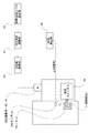
図4は本発明の1実施形態における制御系統図である。この実施形態は、内面研削機に本発明を適用し、内面研削における切込速度(矢印v)を自動的に制御することにより、良好な研削状態を維持して、研削作業の高能率と製品の高品質とを確保するとともに、工具の損傷を未然に防止したものである。
ワーク1は、前掲の図1におけると同様に2ロール1シューによって無心的に支承されて回転しており、砥石スピンドル18は研削砥石5を支持して回転させている。
AEセンサ6は、前掲の図1におけると同様に内面研削機の静止部材に装着され、AE信号sをAE波検出部20に与えている。
FIG. 4 is a control system diagram in one embodiment of the present invention. In this embodiment, the present invention is applied to an internal grinding machine, and the cutting speed (arrow v) in internal grinding is automatically controlled to maintain a good grinding state, thereby improving the efficiency and product of grinding work. This ensures high quality and prevents damage to the tool.
As in FIG. 1 described above, the
The AE sensor 6 is attached to the stationary member of the internal grinding machine in the same manner as in FIG. 1 described above, and gives the AE signal s to the AE
予め、実験的に良好な研削作業を試行し、そのときのAE波レベルを測定して、AE波レベルの目標値を設定する。
上記のAE波レベル目標値を、目標AEレベル設定部22に記憶させる。
一方、AE波検出部20は、AE信号sを解析して実測AE波レベルを算出する。
切込速度演算部21は、「AE波検出部20で算出された実測AE波レベル」と、「目標AE波レベル設定部22に記憶されていたAE波レベル目標値」とを比較演算して、その時点における研削状態の評価をリアルタイムで判定し、判定結果に基づいて切込部制御部23に制御指令を与える。
切込部制御部23は切込駆動モータ19を自動的に制御して「前記の良好な研削作業状態」を再現させるように、砥石スピンドル18の切込速度vを制御する。
An experimentally good grinding operation is tried in advance, the AE wave level at that time is measured, and a target value for the AE wave level is set.
The above AE wave level target value is stored in the target AE
On the other hand, the AE
The cutting
The cutting
1…ワーク
2…上部ロール
3…下部ロール
4…シュー
5…研削砥石
6…AEセンサ
7…ケーブル
8…ワークストッカ
9…調整砥石
10…ブレード
11…研削砥石
12…波高レベル解析回路
13…周波数解析回路
14…砥石損耗度判定回路
15…ディスプレー
16…警告灯
18…砥石スピンドル
19…切込駆動モータ
20…AE波検出部
21…切込速度演算部
22…目標AE波レベル設定部
23…切込軸制御部
s…切込み速度
Z…研削砥石の中心線
DESCRIPTION OF
9 ... Adjusting wheel
10 ... Blade
11 ... Grinding
13. Frequency analysis circuit
14: Grinding wheel wear degree determination circuit
15 ... Display
16 ... Warning light
DESCRIPTION OF
Claims (9)
かつ、検出した電気信号を解析して、研削作業の異状発生の有無、研削ステップの進捗状態、及び研削砥石の損耗状態の少なくとも何れか一つを判定する演算回路を備えていることを特徴とする、研削作業の状態を判定する装置。 The outer periphery of the workpiece (1) having a cylindrical surface is supported unintentionally by the rolls (2, 3) which are rotating members and the shoe (4) which is a stationary member, and the grinding wheel (5) is brought into contact with the workpiece. In the internal grinding machine for grinding, the AE sensor (6) is attached to the shoe, and the ultrasonic vibration radiated by the grinding can be detected as an electric signal.
And an arithmetic circuit that analyzes the detected electrical signal and determines at least one of the occurrence of abnormal grinding operation, the progress of the grinding step, and the wear state of the grinding wheel. A device for determining the state of grinding work.
上記のブレードにAEセンサ(6)が装着されていて、研削によって放射される超音波振動を電気信号として検出し得るようになっており、
かつ、検出した電気信号を解析して、研削作業に異状発生の有無、研削ステップの進捗状態、及び研削砥石の損耗状態を判定する演算回路を備えていることを特徴とする、研削砥石の損耗状態を判定する装置。 The outer periphery of the work (1) having a cylindrical surface is supported unconsciously by the adjusting grindstone (9) as a rotating member and the blade (10) as a stationary member, and the grinding grindstone (11) is brought into contact with the work. In centerless grinding machines that grind
An AE sensor (6) is mounted on the blade, and can detect ultrasonic vibrations radiated by grinding as an electrical signal.
In addition, wear of the grinding wheel is characterized by analyzing the detected electrical signal and comprising an arithmetic circuit for judging whether or not abnormality has occurred in the grinding operation, the progress state of the grinding step, and the wear state of the grinding wheel. A device that determines the state.
かつ、上記判定回路は、特定の周波数範囲の超音波波高を閾値と比較する機能を有するものであることを特徴とする、請求項1または請求項2に記載した研削作業の状態を判定する装置。 The arithmetic circuit has a crest level analysis circuit (12) and a grindstone wear degree determination circuit (14),
3. The apparatus according to claim 1 or 2, wherein the determination circuit has a function of comparing an ultrasonic wave height in a specific frequency range with a threshold value. .
かつ、上記判定回路は、「損耗した砥石が放射する超音波の周波数分布特性」を記憶していて、「解析回路から出力された周波数分布状態」を上記の「記憶している周波数分布特性」と比較する機能を有するものであることを特徴とする、請求項1または請求項2に記載した研削作業の状態を判定する装置。 The arithmetic circuit includes a frequency analysis circuit (13) and a grindstone wear degree determination circuit (14).
In addition, the determination circuit stores “frequency distribution characteristics of ultrasonic waves emitted from a worn grindstone”, and “stores frequency distribution characteristics output from the analysis circuit” as described above. The apparatus for judging the state of the grinding work according to claim 1 or 2, characterized in that the apparatus has a function of comparing with.
上記のシューにAEセンサ(6)を装着しておき、
研削によって放射される超音波振動を上記AEセンサ6により電気信号として検出し、
検出した電気信号を解析して研削作業の状態を自動的に判定することを特徴とする、研削作業の状態を判定する方法。 The outer periphery of the workpiece (1) having a cylindrical surface is supported unintentionally by the rolls (2, 3) which are rotating members and the shoe (4) which is a stationary member, and the grinding wheel (5) is brought into contact with the workpiece. In the internal grinding machine of grinding method
The AE sensor (6) is attached to the above shoe,
The ultrasonic vibration emitted by grinding is detected as an electrical signal by the AE sensor 6;
A method for determining the state of a grinding operation, wherein the state of the grinding operation is automatically determined by analyzing a detected electrical signal.
上記のブレードにAEセンサ(6)を装着しておき、
研削によって放射される超音波振動を上記AEセンサ6により電気信号として検出し、
検出した電気信号を解析して、研削作業の状態を自動的に判定することを特徴とする、研削作業の状態を判定する方法。 The outer periphery of the work (1) having a cylindrical surface is supported unconsciously by the adjusting grindstone (9) as a rotating member and the blade (10) as a stationary member, and the grinding grindstone (11) is brought into contact with the work. In centerless grinding machines that grind
AE sensor (6) is mounted on the above blade,
The ultrasonic vibration emitted by grinding is detected as an electrical signal by the AE sensor 6;
A method for determining the state of a grinding operation, comprising analyzing the detected electrical signal and automatically determining the state of the grinding operation.
検出された超音波の波高を、上記の実測値と比較して研削作業状態を自動的に判定することを特徴とする、請求項5または請求項6に記載した研削作業の状態を判定する方法。 The wave height level of the ultrasonic wave radiated by grinding is measured according to the degree of wear,
The method for determining the state of the grinding operation according to claim 5 or 6, wherein the detected ultrasonic wave height is compared with the measured value to automatically determine the grinding operation state. .
検出された超音波の周波数分布を、上記の実測値と比較して研削作業状態を自動的に判定することを特徴とする、請求項5または請求項6に記載した研削作業の状態を判定する方法。 Measure the frequency distribution of the ultrasonic wave radiated by grinding, corresponding to the degree of wear,
The state of the grinding operation according to claim 5 or 6, wherein the grinding operation state is automatically determined by comparing the detected ultrasonic frequency distribution with the actual measurement value. Method.
上記のシューまたはブレードにAEセンサ(6)を装着しておき、
研削によって放射される超音波振動を上記AEセンサ(6)により電気信号として検出し、
検出した電気信号を解析して研削作業状態を判定し、これを研削作業機器にフイードバックして、研削力を常に一定ならしめるように切り込み制御を行なうことを特徴とする、研削作業の制御方法。
The outer periphery of the work (1) having a cylindrical surface is supported unconsciously by the rolls (2, 3) which are rotating members and the shoes (4) which are stationary members, and the grinding wheel (5) is brought into contact with the work. The outer periphery of the internal grinding machine of the grinding method or the work (1) having a cylindrical surface is instinctively supported by the adjusting grindstone (9) as a rotating member and the blade (10) as a stationary member. In a centerless grinding machine for grinding by bringing the grinding wheel (11) into contact with the workpiece,
Attach the AE sensor (6) to the above shoe or blade,
The ultrasonic vibration emitted by grinding is detected as an electrical signal by the AE sensor (6),
A grinding work control method, comprising: analyzing a detected electrical signal to determine a grinding work state; feeding the result back to a grinding work machine; and performing cutting control so that the grinding force is always constant.
Priority Applications (1)
| Application Number | Priority Date | Filing Date | Title |
|---|---|---|---|
| JP2005107070A JP2006281402A (en) | 2005-04-04 | 2005-04-04 | Method and apparatus for judging condition of grinding operation, and method for controlling grinding operation |
Applications Claiming Priority (1)
| Application Number | Priority Date | Filing Date | Title |
|---|---|---|---|
| JP2005107070A JP2006281402A (en) | 2005-04-04 | 2005-04-04 | Method and apparatus for judging condition of grinding operation, and method for controlling grinding operation |
Publications (1)
| Publication Number | Publication Date |
|---|---|
| JP2006281402A true JP2006281402A (en) | 2006-10-19 |
Family
ID=37403831
Family Applications (1)
| Application Number | Title | Priority Date | Filing Date |
|---|---|---|---|
| JP2005107070A Pending JP2006281402A (en) | 2005-04-04 | 2005-04-04 | Method and apparatus for judging condition of grinding operation, and method for controlling grinding operation |
Country Status (1)
| Country | Link |
|---|---|
| JP (1) | JP2006281402A (en) |
Cited By (11)
| Publication number | Priority date | Publication date | Assignee | Title |
|---|---|---|---|---|
| CN102873638A (en) * | 2012-10-12 | 2013-01-16 | 上海理工大学 | Workpiece radius online detection method in excircle cutting in grinding feeding process |
| JP2013208657A (en) * | 2012-03-30 | 2013-10-10 | Ihi Corp | Machining method and machining system |
| CZ305083B6 (en) * | 2009-07-29 | 2015-04-29 | Technická univerzita v Liberci | Method of monitoring and system for monitoring and evaluating wear of a grinding wheel by means of acoustic emissions generated during grinding process |
| CN105215852A (en) * | 2015-05-29 | 2016-01-06 | 青岛理工大学 | Device and method for measuring abrasion of grinding wheel and G ratio |
| CN107695860A (en) * | 2017-11-07 | 2018-02-16 | 佛山市南海富东机械设备有限公司 | A kind of abrasive disc for polishing marble slabs device |
| JP2018111152A (en) * | 2017-01-10 | 2018-07-19 | ミクロン精密株式会社 | Centerless grinding apparatus and load measuring method |
| WO2018131399A1 (en) * | 2017-01-10 | 2018-07-19 | ミクロン精密株式会社 | Grinding apparatus and grinding method |
| JP2018111151A (en) * | 2017-01-10 | 2018-07-19 | ミクロン精密株式会社 | Grinding apparatus and grinding method |
| JP2019063891A (en) * | 2017-09-28 | 2019-04-25 | ミクロン精密株式会社 | Centerless grinding device and grinding state monitoring method of workpiece |
| CN115609479A (en) * | 2022-10-20 | 2023-01-17 | 中国中材海外科技发展有限公司 | Monitoring method, device, system and storage medium of grinding equipment |
| DE102021127805A1 (en) | 2021-10-26 | 2023-04-27 | Schaeffler Technologies AG & Co. KG | Grinding machine and method of operating a grinding machine |
Citations (5)
| Publication number | Priority date | Publication date | Assignee | Title |
|---|---|---|---|---|
| JPH0373255A (en) * | 1989-08-15 | 1991-03-28 | Seiko Seiki Co Ltd | Processing condition detector of machine tool |
| JPH04159066A (en) * | 1990-10-24 | 1992-06-02 | Nippon Seiko Kk | Centerless grinder |
| JPH06246608A (en) * | 1993-02-26 | 1994-09-06 | Koyo Mach Ind Co Ltd | Method and device for centerless grinding |
| JPH08261818A (en) * | 1995-03-23 | 1996-10-11 | Nissan Motor Co Ltd | Method and apparatus for detecting vibration of rotating body |
| JP2002113659A (en) * | 2000-10-10 | 2002-04-16 | Nagase Integrex Co Ltd | Method of grinding by grinder and grinder |
-
2005
- 2005-04-04 JP JP2005107070A patent/JP2006281402A/en active Pending
Patent Citations (5)
| Publication number | Priority date | Publication date | Assignee | Title |
|---|---|---|---|---|
| JPH0373255A (en) * | 1989-08-15 | 1991-03-28 | Seiko Seiki Co Ltd | Processing condition detector of machine tool |
| JPH04159066A (en) * | 1990-10-24 | 1992-06-02 | Nippon Seiko Kk | Centerless grinder |
| JPH06246608A (en) * | 1993-02-26 | 1994-09-06 | Koyo Mach Ind Co Ltd | Method and device for centerless grinding |
| JPH08261818A (en) * | 1995-03-23 | 1996-10-11 | Nissan Motor Co Ltd | Method and apparatus for detecting vibration of rotating body |
| JP2002113659A (en) * | 2000-10-10 | 2002-04-16 | Nagase Integrex Co Ltd | Method of grinding by grinder and grinder |
Cited By (13)
| Publication number | Priority date | Publication date | Assignee | Title |
|---|---|---|---|---|
| CZ305083B6 (en) * | 2009-07-29 | 2015-04-29 | Technická univerzita v Liberci | Method of monitoring and system for monitoring and evaluating wear of a grinding wheel by means of acoustic emissions generated during grinding process |
| JP2013208657A (en) * | 2012-03-30 | 2013-10-10 | Ihi Corp | Machining method and machining system |
| CN102873638A (en) * | 2012-10-12 | 2013-01-16 | 上海理工大学 | Workpiece radius online detection method in excircle cutting in grinding feeding process |
| CN105215852A (en) * | 2015-05-29 | 2016-01-06 | 青岛理工大学 | Device and method for measuring abrasion of grinding wheel and G ratio |
| WO2018131399A1 (en) * | 2017-01-10 | 2018-07-19 | ミクロン精密株式会社 | Grinding apparatus and grinding method |
| JP2018111152A (en) * | 2017-01-10 | 2018-07-19 | ミクロン精密株式会社 | Centerless grinding apparatus and load measuring method |
| JP2018111151A (en) * | 2017-01-10 | 2018-07-19 | ミクロン精密株式会社 | Grinding apparatus and grinding method |
| DE112017006773B4 (en) | 2017-01-10 | 2022-11-10 | Micron Machinery Co., Ltd. | GRINDING DEVICE AND GRINDING PROCESS |
| JP2019063891A (en) * | 2017-09-28 | 2019-04-25 | ミクロン精密株式会社 | Centerless grinding device and grinding state monitoring method of workpiece |
| CN107695860A (en) * | 2017-11-07 | 2018-02-16 | 佛山市南海富东机械设备有限公司 | A kind of abrasive disc for polishing marble slabs device |
| CN107695860B (en) * | 2017-11-07 | 2023-10-20 | 佛山市高明富东机械制造有限公司 | Marble slab polishing millstone device |
| DE102021127805A1 (en) | 2021-10-26 | 2023-04-27 | Schaeffler Technologies AG & Co. KG | Grinding machine and method of operating a grinding machine |
| CN115609479A (en) * | 2022-10-20 | 2023-01-17 | 中国中材海外科技发展有限公司 | Monitoring method, device, system and storage medium of grinding equipment |
Similar Documents
| Publication | Publication Date | Title |
|---|---|---|
| JP7627225B2 (en) | Method for automatic process monitoring during continuous generating grinding | |
| US20090129882A1 (en) | Methods, Systems, and Devices for Monitoring Tools in a Dental Milling Machine | |
| KR101462312B1 (en) | Tool monitoring system of machine tools and method thereof | |
| US10189136B2 (en) | Power tool with digital variable reluctance motor control | |
| JP2016135511A (en) | Processing abnormality detection device and processing abnormality detection method | |
| JP3291677B2 (en) | Method and apparatus for monitoring condition of machining blade for machine tool | |
| JP2017208432A (en) | Method for determining physical property of monocrystalline silicon carbide substrate and method for manufacturing monocrystalline silicon carbide substrate | |
| JP2020069638A (en) | Dressing surface evaluation apparatus, dressing device, and grinding device | |
| JPH09174383A (en) | Method and device for detecting abnormality of rotating tool | |
| JP6489889B2 (en) | Surface processing equipment | |
| JP6314885B2 (en) | Damage prevention system, grinding wheel | |
| US20240149384A1 (en) | Method for detecting the wear of a milling cutter of a key-duplicating machine | |
| JP6808038B2 (en) | Tool life detection device and tool life detection method | |
| JP2020069639A (en) | Grinding surface condition evaluation device and grinding processing device | |
| US20240001507A1 (en) | Method for controlling and/or monitoring a workpiece machining process | |
| JP2023515591A (en) | Devices for predicting blade failure of bandsaw blades in band saws | |
| KR20160079372A (en) | Monitoring device of tool install condition for machine tool | |
| KR101476853B1 (en) | Spindle vibration detection and spindle speed automatic control system of machine tool and method thereof | |
| JPH0985586A (en) | Detecting device and detecting method of cutting state by rotary cutting tool | |
| KR101941642B1 (en) | A pipe length inspection device mounted on the chamfering machine | |
| JP7576594B2 (en) | Cutting system and cutting method | |
| US20240383088A1 (en) | Method of operating a machine tool apparatus | |
| JP3850780B2 (en) | Workpiece supply abnormality detection method and workpiece supply abnormality detection device | |
| JP6612696B2 (en) | Dressing method and workpiece grinding method | |
| JPH0557608A (en) | Grinding machine dressing device |
Legal Events
| Date | Code | Title | Description |
|---|---|---|---|
| A621 | Written request for application examination |
Effective date: 20080327 Free format text: JAPANESE INTERMEDIATE CODE: A621 |
|
| A977 | Report on retrieval |
Effective date: 20090319 Free format text: JAPANESE INTERMEDIATE CODE: A971007 |
|
| A131 | Notification of reasons for refusal |
Free format text: JAPANESE INTERMEDIATE CODE: A131 Effective date: 20100427 |
|
| A02 | Decision of refusal |
Effective date: 20100921 Free format text: JAPANESE INTERMEDIATE CODE: A02 |