JP2006281925A - Vehicle integrated control device - Google Patents
Vehicle integrated control device Download PDFInfo
- Publication number
- JP2006281925A JP2006281925A JP2005102672A JP2005102672A JP2006281925A JP 2006281925 A JP2006281925 A JP 2006281925A JP 2005102672 A JP2005102672 A JP 2005102672A JP 2005102672 A JP2005102672 A JP 2005102672A JP 2006281925 A JP2006281925 A JP 2006281925A
- Authority
- JP
- Japan
- Prior art keywords
- control
- transmission
- target
- control target
- vehicle
- Prior art date
- Legal status (The legal status is an assumption and is not a legal conclusion. Google has not performed a legal analysis and makes no representation as to the accuracy of the status listed.)
- Pending
Links
Images

Classifications
-
- B—PERFORMING OPERATIONS; TRANSPORTING
- B60—VEHICLES IN GENERAL
- B60W—CONJOINT CONTROL OF VEHICLE SUB-UNITS OF DIFFERENT TYPE OR DIFFERENT FUNCTION; CONTROL SYSTEMS SPECIALLY ADAPTED FOR HYBRID VEHICLES; ROAD VEHICLE DRIVE CONTROL SYSTEMS FOR PURPOSES NOT RELATED TO THE CONTROL OF A PARTICULAR SUB-UNIT
- B60W10/00—Conjoint control of vehicle sub-units of different type or different function
- B60W10/04—Conjoint control of vehicle sub-units of different type or different function including control of propulsion units
- B60W10/06—Conjoint control of vehicle sub-units of different type or different function including control of propulsion units including control of combustion engines
-
- B—PERFORMING OPERATIONS; TRANSPORTING
- B60—VEHICLES IN GENERAL
- B60W—CONJOINT CONTROL OF VEHICLE SUB-UNITS OF DIFFERENT TYPE OR DIFFERENT FUNCTION; CONTROL SYSTEMS SPECIALLY ADAPTED FOR HYBRID VEHICLES; ROAD VEHICLE DRIVE CONTROL SYSTEMS FOR PURPOSES NOT RELATED TO THE CONTROL OF A PARTICULAR SUB-UNIT
- B60W10/00—Conjoint control of vehicle sub-units of different type or different function
- B60W10/10—Conjoint control of vehicle sub-units of different type or different function including control of change-speed gearings
- B60W10/11—Stepped gearings
-
- B—PERFORMING OPERATIONS; TRANSPORTING
- B60—VEHICLES IN GENERAL
- B60W—CONJOINT CONTROL OF VEHICLE SUB-UNITS OF DIFFERENT TYPE OR DIFFERENT FUNCTION; CONTROL SYSTEMS SPECIALLY ADAPTED FOR HYBRID VEHICLES; ROAD VEHICLE DRIVE CONTROL SYSTEMS FOR PURPOSES NOT RELATED TO THE CONTROL OF A PARTICULAR SUB-UNIT
- B60W30/00—Purposes of road vehicle drive control systems not related to the control of a particular sub-unit, e.g. of systems using conjoint control of vehicle sub-units
- B60W30/18—Propelling the vehicle
- B60W30/188—Controlling power parameters of the driveline, e.g. determining the required power
-
- F—MECHANICAL ENGINEERING; LIGHTING; HEATING; WEAPONS; BLASTING
- F16—ENGINEERING ELEMENTS AND UNITS; GENERAL MEASURES FOR PRODUCING AND MAINTAINING EFFECTIVE FUNCTIONING OF MACHINES OR INSTALLATIONS; THERMAL INSULATION IN GENERAL
- F16H—GEARING
- F16H63/00—Control outputs from the control unit to change-speed- or reversing-gearings for conveying rotary motion or to other devices than the final output mechanism
- F16H63/40—Control outputs from the control unit to change-speed- or reversing-gearings for conveying rotary motion or to other devices than the final output mechanism comprising signals other than signals for actuating the final output mechanisms
- F16H63/50—Signals to an engine or motor
-
- B—PERFORMING OPERATIONS; TRANSPORTING
- B60—VEHICLES IN GENERAL
- B60W—CONJOINT CONTROL OF VEHICLE SUB-UNITS OF DIFFERENT TYPE OR DIFFERENT FUNCTION; CONTROL SYSTEMS SPECIALLY ADAPTED FOR HYBRID VEHICLES; ROAD VEHICLE DRIVE CONTROL SYSTEMS FOR PURPOSES NOT RELATED TO THE CONTROL OF A PARTICULAR SUB-UNIT
- B60W2540/00—Input parameters relating to occupants
- B60W2540/10—Accelerator pedal position
-
- B—PERFORMING OPERATIONS; TRANSPORTING
- B60—VEHICLES IN GENERAL
- B60W—CONJOINT CONTROL OF VEHICLE SUB-UNITS OF DIFFERENT TYPE OR DIFFERENT FUNCTION; CONTROL SYSTEMS SPECIALLY ADAPTED FOR HYBRID VEHICLES; ROAD VEHICLE DRIVE CONTROL SYSTEMS FOR PURPOSES NOT RELATED TO THE CONTROL OF A PARTICULAR SUB-UNIT
- B60W2710/00—Output or target parameters relating to a particular sub-units
- B60W2710/06—Combustion engines, Gas turbines
- B60W2710/0666—Engine torque
-
- B—PERFORMING OPERATIONS; TRANSPORTING
- B60—VEHICLES IN GENERAL
- B60W—CONJOINT CONTROL OF VEHICLE SUB-UNITS OF DIFFERENT TYPE OR DIFFERENT FUNCTION; CONTROL SYSTEMS SPECIALLY ADAPTED FOR HYBRID VEHICLES; ROAD VEHICLE DRIVE CONTROL SYSTEMS FOR PURPOSES NOT RELATED TO THE CONTROL OF A PARTICULAR SUB-UNIT
- B60W2720/00—Output or target parameters relating to overall vehicle dynamics
- B60W2720/10—Longitudinal speed
- B60W2720/106—Longitudinal acceleration
Landscapes
- Engineering & Computer Science (AREA)
- Mechanical Engineering (AREA)
- Chemical & Material Sciences (AREA)
- Combustion & Propulsion (AREA)
- Transportation (AREA)
- General Engineering & Computer Science (AREA)
- Automation & Control Theory (AREA)
- Control Of Driving Devices And Active Controlling Of Vehicle (AREA)
- Control Of Vehicle Engines Or Engines For Specific Uses (AREA)
- Control Of Transmission Device (AREA)
Abstract
【課題】 本発明は、エンジントルクと変速段の応答性等に相違を考慮して、それぞれの最適なタイミングでの制御が可能な車両統合制御装置の提供を目的とする。
【解決手段】 駆動源とトランスミッションとの組み合わせからなるパワートレインを搭載した車両に適用される車両統合制御装置において、運転者又は自動運転装置の要求に基づいて制御目標値F1を一次的に生成し、該制御目標値F1に基づいて、該制御目標値F1と同一の物理量次元で且つ互いに値が異なる2つの制御目標値F1EGN、F1TMを中間的に生成し、該中間的に生成したそれぞれの制御目標値F1EGN、F1TMに基づいて、駆動源及びトランスミッションそれぞれの制御に見合った物理量次元又は形式の制御目標(目標エンジントルク、目標ギア段)を最終的に生成し、該最終的に生成したそれぞれの制御目標に向けて駆動源及びトランスミッションを制御する。
【選択図】 図2PROBLEM TO BE SOLVED: To provide a vehicle integrated control device capable of control at each optimum timing in consideration of a difference in engine torque and responsiveness of a shift stage.
In a vehicle integrated control device applied to a vehicle equipped with a power train composed of a combination of a drive source and a transmission, a control target value F1 is temporarily generated based on a request from a driver or an automatic driving device. Based on the control target value F1, two control target values F1 EGN and F1 TM having the same physical quantity dimension as the control target value F1 and different values are generated in the middle, and the intermediate generated Based on the control target values F1 EGN and F1 TM , the physical quantity dimension or type of control target (target engine torque, target gear stage) suitable for the control of the drive source and transmission is finally generated, and finally The drive source and the transmission are controlled for each generated control target.
[Selection] Figure 2
Description
本発明は、駆動源とトランスミッションとの組み合わせからなるパワートレインを搭載した車両に搭載され、駆動源とトランスミッションとを統合的に制御する車両統合制御装置に関する。 The present invention relates to a vehicle integrated control device that is mounted on a vehicle equipped with a power train that is a combination of a drive source and a transmission, and that integrally controls the drive source and the transmission.
従来から、アクセル開度や車速等に基づいて算出した目標車軸トルクから目標エンジントルクと目標変速段を算出する技術が知られている(例えば、特許文献1参照)。
ところで、エンジンとトランスミッションとを互いに関連付けられた形態で統合的に制御するには、例えばアクセル操作量に基づいて決定される同一の目標値から、それぞれの最終的な制御目標値(例えば目標エンジントルクと目標変速段)を決定する必要がある。 By the way, in order to integrally control the engine and the transmission in a mutually associated form, for example, from the same target value determined based on the accelerator operation amount, each final control target value (for example, target engine torque) And the target gear position) must be determined.
しかしながら、エンジントルクと変速段の応答性等に相違があるため、上述の従来技術のように、それぞれ同一の目標車軸トルクから目標エンジントルクと目標変速段を算出する構成では、個別的な最適なタイミングでの制御が困難であり、例えば、駆動力の急変を防止するために制御目標値になましを入れると、変速遅れが起き易くなる等の問題が発生する。 However, since there is a difference in the response of the engine torque and the shift speed, etc., in the configuration in which the target engine torque and the target shift speed are calculated from the same target axle torque, respectively, as in the above-described conventional technology, individual optimum Control at the timing is difficult. For example, if smoothing is applied to the control target value in order to prevent a sudden change in the driving force, there arises a problem that a shift delay is likely to occur.
そこで、本発明は、エンジントルクと変速段の応答性等に相違を考慮して、それぞれの最適なタイミングでの制御が可能な車両統合制御装置の提供を目的とする。 Accordingly, an object of the present invention is to provide a vehicle integrated control device capable of performing control at each optimum timing in consideration of differences in engine torque and responsiveness of gears.
上記課題を解決するため、本発明の一局面によれば、駆動源とトランスミッションとの組み合わせからなるパワートレインを搭載した車両に適用され、駆動源とトランスミッションとを統合的に制御する車両統合制御装置において、
運転者又は自動運転装置の要求に基づいて制御目標値を一次的に生成し、該制御目標値に基づいて、該制御目標値と同一の物理量次元で且つ互いに値が異なる2つの制御目標値を中間的に生成し、該中間的に生成したそれぞれの制御目標値に基づいて、駆動源及びトランスミッションそれぞれの制御に見合った物理量次元又は形式の制御目標を最終的に生成し、該最終的に生成したそれぞれの制御目標に向けて駆動源及びトランスミッションを制御することを特徴とする車両統合制御装置が提供される。
In order to solve the above-described problems, according to one aspect of the present invention, a vehicle integrated control device that is applied to a vehicle equipped with a power train that is a combination of a drive source and a transmission and that integrally controls the drive source and the transmission. In
Based on the request of the driver or the automatic driving device, a control target value is temporarily generated, and based on the control target value, two control target values having the same physical quantity dimension as the control target value and different values are obtained. Generate intermediately, and finally generate a physical quantity dimension or type of control target suitable for the control of each drive source and transmission based on the intermediately generated control target value, and finally generate this A vehicle integrated control device is provided that controls a drive source and a transmission toward each control target.
本局面において、車両統合制御装置は、運転者又は自動運転装置の要求に基づいて一次的に生成される制御目標を表す信号を、駆動源を制御する駆動源制御ユニットへと伝達する第1の信号伝達系と、同信号を、トランスミッションを制御するトランスミッション制御ユニットへと伝達する第2の信号伝達系とを備えてよい。また、車両統合制御装置は、第1の信号伝達系で伝達される前記信号を、第2の信号伝達系で伝達される同信号とは異なる波形へと補正することで、前記中間的な制御目標値を生成するものであってよい。 In this aspect, the vehicle integrated control device transmits a signal representing a control target that is primarily generated based on a request from the driver or the automatic driving device to a drive source control unit that controls the drive source. You may provide a signal transmission system and the 2nd signal transmission system which transmits the same signal to the transmission control unit which controls a transmission. Further, the vehicle integrated control device corrects the signal transmitted by the first signal transmission system to a waveform different from the signal transmitted by the second signal transmission system, so that the intermediate control is performed. The target value may be generated.
本発明によれば、エンジントルクと変速段の応答性等に相違を考慮して、それぞれの最適なタイミングでの制御が可能な車両統合制御装置を得ることができる。 According to the present invention, it is possible to obtain a vehicle integrated control device capable of performing control at each optimum timing in consideration of differences in engine torque and responsiveness of gears.
以下、図面を参照して、本発明を実施するための最良の形態の説明を行う。 The best mode for carrying out the present invention will be described below with reference to the drawings.
先ず、図1を参照して、本発明の車両統合制御装置が搭載されてよい車両の概要を説明する。 First, with reference to FIG. 1, the outline | summary of the vehicle in which the vehicle integrated control apparatus of this invention may be mounted is demonstrated.
この車両は、前後左右にそれぞれ車輪100を備える。図1において「FL」は左前輪、「FR」は右前輪、「RL」は左後輪、「RR」は左後輪をそれぞれ示す。
This vehicle includes
この車両は、動力源としてエンジン140を備える。尚、駆動源は、エンジンに限定されず、電気モータのみやエンジンと電気モータとの組み合わせであってもよく、電気モータの動力源は、2次電池や燃料電池であってよい。
This vehicle includes an
エンジン140の運転状態は、運転者によるアクセルペダル200(車両の前後運動を制御するために運転者が操作する操作部材の一例である。)の操作量に応じて電気的に制御される。エンジン140の運転状態は、また、必要に応じて、運転者によるアクセルペダル200の操作とは無関係に自動的に制御される。
The driving state of
このようなエンジン140の電気的な制御は、例えば、図示しないが、エンジン140の吸気マニホールド内に配置されるスロットルバルブの開度(即ち、スロットル開度)を電気的に制御することや、エンジン140の燃焼室に噴射される燃料の量を電気的に制御することや、バルブ開閉タイミングを調整するインテークカムシャフトの位相を電気的に制御することで実現することが可能である。
Such electrical control of the
この車両は、左右前輪が転動輪、左右後輪が駆動輪である後輪駆動式である。そのため、エンジン140の出力軸は、トルクコンバータ220、トランスミッション240、プロペラシャフト260及びデファレンシャル280と、各後輪と共に回転するドライブシャフト300とをそれらの順に介して各後輪に連結されている。尚、トルクコンバータ220、トランスミッション240、プロペラシャフト260及びデファレンシャル280は、左右後輪に共通な動力伝達要素である。尚、車両は、後輪駆動式である必要はなく、例えば、左右前輪が駆動輪、左右後輪が転動輪である前輪駆動式であっても、全部の車輪が駆動輪となる4WD式であってもよい。
This vehicle is a rear wheel drive type in which left and right front wheels are rolling wheels and left and right rear wheels are drive wheels. Therefore, the output shaft of
トランスミッション240は、図示しない自動変速機を備えている。この自動変速機は、エンジン140の回転速度をトランスミッション240のアウトプットシャフトの回転速度に変速する際の変速比を電気的に制御する。尚、自動変速機は、有段変速機であっても、無段階変速機(CVT)であってもよい。
The
車両は、運転者により回転操作されるステアリングホイール440を備えている。このステアリングホイール440には、操舵反力付与装置480により、運転者による回転操作(以下、「操舵」ともいう。)に応じた反力が操舵反力として電気的に付与される。その操舵反力は、電気的に制御可能とされている。
The vehicle includes a
左右前輪の向き、即ち前輪舵角は、フロントステアリング装置500によって電気的に変化させられる。フロントステアリング装置500は、運転者によりステアリングホイール440が回転操作された角度、即ち操舵角に基づいて前輪操舵角を制御し、また、必要に応じて、その回転操作とは無関係に前輪操舵角を自動的に制御する。即ち、ステアリングホイール440と左右前輪とは機械的に絶縁されていてもよい。
The direction of the left and right front wheels, that is, the front wheel steering angle is electrically changed by the
左右後輪の向き、即ち後輪舵角も、前輪舵角と同様に、リアステアリング装置520によって電気的に変化させられる。
The direction of the left and right rear wheels, that is, the rear wheel steering angle, is also electrically changed by the
各車輪100には、その回転を抑制するために作動させられるブレーキ560が設けられている。各ブレーキ560は、運転者によるブレーキペダル580(車両の前後運動を制御するために運転者が操作する操作部材の一例である。)の操作量に応じて電気的に制御され、また、必要に応じて、自動的に各車輪100が個別に制御される。
Each
この車両においては、各車輪100は、各サスペンション620を介して車体(図示せず)に懸架されている。各サスペンション620の懸架特性は、個別に電気的に制御可能とされている。
In this vehicle, each
以上のように説明した各構成要素は、それを電気的に作動させるために作動させられる以下のアクチュエータを備えている。
(1)エンジン140を電気的に制御するためのアクチュエータ
(2)トランスミッション240を電気的に制御するためのアクチュエータ
(3)操舵反力付与装置480を電気的に制御するためのアクチュエータ
(4)フロントステアリング装置500を電気的に制御するためのアクチュエータ
(5)リアステアリング装置520を電気的に制御するためのアクチュエータ
(6)ブレーキ560を電気的に制御するためのアクチュエータ
(7)サスペンション620を電気的に制御するためのアクチュエータ。
Each of the constituent elements described above includes the following actuators that are actuated to electrically actuate them.
(1) Actuator for electrically controlling the engine 140 (2) Actuator for electrically controlling the transmission 240 (3) Actuator for electrically controlling the steering reaction force applying device 480 (4) Front Actuator for electrically controlling the steering device 500 (5) Actuator for electrically controlling the rear steering device 520 (6) Actuator for electrically controlling the brake 560 (7) Electrically actuating the
尚、これらアクチュエータは、代表的なものだけを列挙したものであり、車両の仕様によっては、これらのアクチュエータの何れかが欠けることもあり、或いは、その他のアクチュエータ(例えば、ステアリングホイール440の操舵量と転舵輪の転舵量との比(ステアリングレシオ)を電気的に制御するためのアクチュエータ、アクセルペダル200の反力を電気的に制御するためのアクチュエータ等)が付加されることもあり、従って、本発明は、特にアクチュエータの構成によって限定されることはない。
These actuators are only representative ones. Depending on the specifications of the vehicle, any of these actuators may be missing, or other actuators (for example, the steering amount of the steering wheel 440). And an actuator for electrically controlling the ratio of the steered wheel to the steered amount (steering ratio), an actuator for electrically controlling the reaction force of the
図1に示すように、車両統合制御装置は、以上のように説明した各種アクチュエータに電気的に接続された状態で車両に搭載されている。車両統合制御装置は、図示しないバッテリを電力源として動作する。 As shown in FIG. 1, the vehicle integrated control device is mounted on the vehicle in a state where it is electrically connected to the various actuators described above. The vehicle integrated control device operates using a battery (not shown) as a power source.
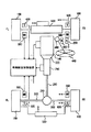
図2は、本実施例の車両統合制御装置の一実施例を示すシステム構成図である。 FIG. 2 is a system configuration diagram showing an embodiment of the vehicle integrated control device of the present embodiment.
尚、以下で登場する各マネージャ(及びモデル)は、通常的なECU(電子制御ユニット)と同様、マイクロコンピュータによって構成されており、例えば、制御プログラムを格納するROM、演算結果等を格納する読書き可能なRAM、タイマ、カウンタ、入力インターフェイス、及び出力インターフェイス等を有する装置を意味する。また、以下では、機能的に分けて各制御ユニットを例えばP-DRMやVDMなどと命名しているが、これらは必ずしも物理的に独立した構成である必要はなく、適切なソフトウェア構成により一体的に具現化されてよい。 In addition, each manager (and model) that appears below is configured by a microcomputer, like a normal ECU (electronic control unit). For example, a ROM that stores a control program, a reading that stores calculation results, and the like. A device having a RAM, a timer, a counter, an input interface, an output interface, and the like that can be used. Also, in the following, each control unit is functionally divided and named as, for example, P-DRM or VDM. May be embodied.
図2に示すように、駆動系システムの初段には、駆動系のドライバ意思抽出部として機能するマネージャ(以下、Power-Train Driver Model:P-DRMという。)が配置される。駆動系システムの初段には、P-DRMと並列的に、ドライバ運転補佐・代行システム(以下、Driver Support System:DSSという。)が配置される。 As shown in FIG. 2, a manager (hereinafter referred to as “Power-Train Driver Model: P-DRM”) that functions as a drive intention extraction unit of the drive system is arranged in the first stage of the drive system. In the first stage of the drive system, a driver operation assistant / substitute system (hereinafter referred to as Driver Support System: DSS) is arranged in parallel with the P-DRM.
P-DRMの前段には、アクセルセンサが設定される。アクセルセンサは、ドライバの意思が直接的に入力されるアクセルペダル200の操作量に応じた電気的信号を発生する。
An accelerator sensor is set before the P-DRM. The accelerator sensor generates an electrical signal corresponding to the amount of operation of the
DSSの前段には、車輪速センサが設定される。車輪速センサは、車両の各車輪100に設定され、車輪100の所定回転角毎にパルス信号を出力する。
A wheel speed sensor is set in front of the DSS. The wheel speed sensor is set for each
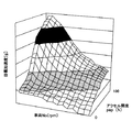
P-DRMには、アクセルセンサからの信号と共に、車輪速センサからの信号が入力される。P-DRM内部の初段では、先ず、目標駆動力算出部にて、アクセルセンサ及び車輪速センサからそれぞれ入力される電気信号に基づくアクセル開度[%]及び車速No[prm]に応じた目標駆動力F1が算出される。目標駆動力F1は、先ず、例えば図3に示すような3次元マップを用いて、アクセル開度[%]と車速[prm]とをパラメータとして、目標加速度G[m/s2]を算出し、次いで、目標加速度G[m/s2]を力の物理量次元[N]に変換して目標駆動力を導出し、最後に、当該目標駆動力を、走行抵抗[N]や道路勾配に基づく登坂勾配補償量[N] により補正することで導出されてよい。 A signal from the wheel speed sensor is input to the P-DRM together with a signal from the accelerator sensor. In the first stage inside the P-DRM, first, the target driving force calculation unit performs target driving according to the accelerator opening [%] and the vehicle speed No [prm] based on the electric signals respectively input from the accelerator sensor and the wheel speed sensor. A force F1 is calculated. For the target driving force F1, first, for example, using a three-dimensional map as shown in FIG. 3, the target acceleration G [m / s 2 ] is calculated using the accelerator opening [%] and the vehicle speed [prm] as parameters. Next, the target acceleration G [m / s 2 ] is converted into the physical quantity dimension [N] of the force to derive the target driving force, and finally, the target driving force is based on the running resistance [N] and the road gradient. It may be derived by correcting with the uphill slope compensation amount [N].
本実施例の目標駆動力算出部は、このようにして導出した目標駆動力F1[N]に基づいて、2つの目標駆動力F1EGN、F1TM[N]を生成する。2つの目標駆動力F1EGN、F1TMは、図2に示すように、それぞれ、目標駆動力算出部から2つに分流した信号線により、エンジン制御ユニット及びT/M制御ユニットへと伝達される。以下、目標駆動力F1EGN、F1TMが伝達されるルートを、それぞれ「エンジン制御系伝達ルート」と「T/M制御系伝達ルート」という。 The target driving force calculation unit of the present embodiment generates two target driving forces F1 EGN and F1 TM [N] based on the target driving force F1 [N] derived in this way. As shown in FIG. 2, the two target driving forces F1 EGN and F1 TM are respectively transmitted to the engine control unit and the T / M control unit through signal lines branched into two from the target driving force calculation unit. . Hereinafter, the routes through which the target driving forces F1 EGN and F1 TM are transmitted are referred to as “engine control system transmission route” and “T / M control system transmission route”, respectively.
本実施例では、このように同一の目標駆動力F1から生成される2つの目標駆動力F1EGN、F1TMが、それぞれのルートを介して、互いに同期が取れた状態で、後述するように、エンジン制御ユニット及びT/M制御ユニットへと出力され、エンジン制御及び変速制御の利用に供されることになる。これにより、互いに適切に関連付けられた状態でエンジン制御及び変速制御の2つの制御を統合的に実現することが可能となる。 In the present embodiment, the two target driving forces F1 EGN and F1 TM generated from the same target driving force F1 are synchronized with each other via the respective routes, as will be described later. It is output to the engine control unit and the T / M control unit, and is used for engine control and shift control. As a result, it is possible to integrally realize the two controls of the engine control and the shift control in a state where they are appropriately associated with each other.
また、本実施例では、同一の目標駆動力F1から、エンジン制御及び変速制御に供される2つの目標駆動力F1EGN、F1TMを生成するので、エンジン制御及び変速制御の2つの制御の関連性を維持しつつ、それぞれの制御の固有の特性に合った個別的な目標駆動力補正を行うことが可能となる。 In this embodiment, since the two target drive forces F1 EGN and F1 TM used for engine control and shift control are generated from the same target drive force F1, the relationship between the two controls, engine control and shift control, is generated. Thus, it is possible to perform individual target driving force correction that matches the specific characteristics of each control while maintaining the characteristics.
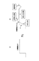
図4は、かかる目標駆動力の補正態様の説明図である。図4(A)は、目標駆動力F1の変化態様の一例を示す。図4(B)は、目標駆動力F1(破線)をエンジン制御用に補正して得られる目標駆動力F1EGN(実線)の一例を示す。 FIG. 4 is an explanatory diagram of a correction mode of the target driving force. FIG. 4A shows an example of how the target driving force F1 changes. FIG. 4B shows an example of the target driving force F1 EGN (solid line) obtained by correcting the target driving force F1 (broken line) for engine control.
エンジン制御では、図4(B)に示すように、駆動力伝達系の効率分(損失分)の駆動力を補償する処理、駆動力が急変してドライバビリティ(運転・操縦性)に影響を及ぼさないようになます処理、駆動力の応答遅れ分を補償する処理、駆動力伝達系の制振制御(ジャーク、ピッチやチップイン低減のための制振制御)等のための処理、等々、目標駆動力に対してエンジン制御固有の補正処理を行う必要がある。 In engine control, as shown in Fig. 4 (B), processing to compensate for the driving force for the efficiency (loss) of the driving force transmission system, the driving force changes suddenly and drivability (driving / maneuverability) is affected. Processing to prevent it from hitting, processing to compensate for response delay of driving force, processing for vibration control of driving force transmission system (vibration control to reduce jerk, pitch and chip-in), etc., etc. It is necessary to perform correction processing specific to engine control for the target driving force.
かかる補正処理を変速制御に反映させると、エンジントルクと変速段の応答性等に相違があるため、変速制御に悪影響を及ぼしうる。例えば図4(B)に示すように目標駆動力を過渡的になましたり揺らしたりする補正を変速制御に反映させると、変速遅れや変速ハンチング(変速比の周期的な変動・乱調状態)などの問題が起きる。 If such correction processing is reflected in the shift control, there is a difference between the response of the engine torque and the shift speed, and the shift control can be adversely affected. For example, as shown in Fig. 4 (B), if a correction that makes the target drive force transient or fluctuates is reflected in the shift control, shift delay, shift hunting (periodic fluctuation of the gear ratio, turbulent state), etc. Problem occurs.
これに対して、本実施例では、上述の如く、同一の目標駆動力F1から、エンジン制御用の目標駆動力F1EGNと変速制御用の目標駆動力F1TMと別々に生成するので、エンジン制御用の目標駆動力F1EGNのみに上述のような各種補正を行うことで、かかる補正を変速制御用の目標駆動力F1TMに反映させないことができる。 In contrast, in the present embodiment, as described above, since the target drive force F1 EGN for engine control and the target drive force F1 TM for shift control are generated separately from the same target drive force F1, engine control is performed. By performing the above-described various corrections only on the target driving force F1 EGN for use, it is possible to prevent such correction from being reflected on the target driving force F1 TM for shift control.
このようにして導出される2つの目標駆動力F1EGN、F1TMは、それぞれのルートにおいて、図2に示すように、DSSからの要求がある場合は、DSSからの要求駆動力との調停処理を受ける。 The two target driving forces F1 EGN and F1 TM derived in this way are arbitrated with the required driving force from the DSS when there is a request from the DSS in each route as shown in FIG. Receive.
DSSは、カメラやレーダー等の周囲障害物情報、ナビゲーションシステムから得られる道路情報や周囲環境情報、ナビゲーションシステムのGPS測位装置から得られる自車位置情報、或いは、外部センタ施設との通信、車車間通信や路車間通信を介して得られる各種外部情報に基づいて、ドライバ意思に代わる適切な要求又はドライバ意思結果に対する適切な補正要求を行う。これら要求として典型的な例は、オートクルーズ制御やその類の自動又は半自動走行制御実施時にDSSから出される要求や、障害物回避等のための介入減速制御や操舵補助制御実施時にDSSから出される要求である。 DSS is information on surrounding obstacles such as cameras and radar, road information and environment information obtained from the navigation system, own vehicle position information obtained from the GPS positioning device of the navigation system, or communication with external center facilities, Based on various external information obtained through communication and road-to-vehicle communication, an appropriate request in place of the driver's intention or an appropriate correction request for the driver's intention result is made. Typical examples of these requests are those issued from the DSS when performing auto-cruise control or similar automatic or semi-automatic traveling control, or issued from the DSS when performing intervention deceleration control or steering assist control for obstacle avoidance, etc. It is a request.
このようにして必要に応じて調停を経た目標駆動力F1EGN、F1TM[N]は、パワートレーンマネージャ(以下、Power-Train
Manager:PTMという。)へと出力される。PTMは、駆動系の要求調和部として機能するマネージャである。
The target driving forces F1 EGN and F1 TM [N] that have undergone arbitration as necessary in this way are the power train manager (hereinafter referred to as Power-Train).
Manager: PTM. ). The PTM is a manager that functions as a request harmony part of a drive system.
PTMの初段では、P-DRMから上述の如く入力される目標駆動力F1EGN、F1TM[N]が、動的安定化システム系のマネージャ(以下、Vehicle
Dynamics Manager:VDMという。)に送信(公開)される。VDMは、制動系のドライバ意思抽出部として機能するマネージャ(以下、Brake Driver Model:B-DRMという。)の後段に配置される
VDMは、車両運動調和部として機能するマネージャである。尚、車両の動的挙動を安定化させるシステムとしては、トラクションコントロールシステム(滑りやすい路面での発進や加速時に生じやすい駆動輪のムダな空転を抑制するシステム。)、滑りやすい路面に進入した時などの車両の横滑りを抑制するシステム、コーナリング時に安定限界に達した場合にスピンやコースアウトを防止すべく車体姿勢を安定させるシステム、4WDの左右後輪の駆動力差をアクティブに生成してヨーモーメントを発生させるシステムが代表例として挙げられる。
In the first stage of the PTM, the target driving forces F1 EGN and F1 TM [N] input from the P-DRM as described above are the dynamic stabilization system manager (hereinafter referred to as Vehicle).
Dynamics Manager: VDM. ). The VDM is arranged after the manager (hereinafter referred to as Brake Driver Model: B-DRM) that functions as a driver intention extraction unit of the braking system. The VDM is a manager that functions as a vehicle motion harmony unit. In addition, as a system that stabilizes the dynamic behavior of the vehicle, a traction control system (a system that suppresses unnecessary idling of driving wheels that easily occurs when starting or accelerating on a slippery road surface), or when entering a slippery road surface A system that suppresses the side slip of the vehicle, a system that stabilizes the vehicle body posture to prevent spin and course out when the stability limit is reached during cornering, and a yaw moment by actively generating the driving force difference between the left and right rear wheels of the 4WD A typical example is a system that generates
尚、VDMの後段には、ブレーキ560のアクチュエータを駆動制御するブレーキ制御ユニットと並列的に、フロントステアリング装置500及びリアステアリング装置520のアクチュエータを駆動制御するステア制御ユニットや、サスペンション620のアクチュエータを駆動制御するサス制御ユニットが設定される。尚、B-DRM内部では、ブレーキセンサから入力される電気信号は、目標制動力算出部にて目標制動力に変換され、VDMを介して、ブレーキ制御ユニットへと出力される。尚、本明細書では、詳説しないが、目標制動力算出部にて算出された目標制動力は、以下で詳説する目標駆動力F1EGN、F1TMと同様又は類似する態様で、各種補正(調停)を受けながらブレーキ制御ユニットへと出力されることになる。
In addition, a steering control unit for driving and controlling the actuators of the
VDMの駆動力補正部は、上述の如く主にドライバ意思に応じて一次的に決定された目標制動力F1に対して、車両の動的挙動を安定化させる観点から2次的な補正要求を行う。即ち、VDMの駆動力補正部は、公開される目標駆動力F1EGN、F1TMに対して、必要に応じて、補正要求を行う。この際、VDMの駆動力補正部は、好ましくは、目標駆動力F1EGN、F1TMに対して増減する補正量ΔFを要求するのではなく、目標駆動力F1EGN、F1TMに代わるべき目標駆動力F1EGN、F1TMの絶対量を要求する。以下、このようにして、目標駆動力F1EGN、F1TMに基づいて生成されるVDMからの絶対量による目標駆動力を、「目標駆動力F2EGN、F2TM」とする。 The driving force correction unit of the VDM makes a secondary correction request from the viewpoint of stabilizing the dynamic behavior of the vehicle with respect to the target braking force F1 that is primarily determined according to the driver's intention as described above. Do. That is, the VDM driving force correction unit makes a correction request to the disclosed target driving forces F1 EGN and F1 TM as necessary. At this time, the driving force correction portion of the VDM are preferably target driving force F1 EGN, rather than requiring a correction amount ΔF increased or decreased with respect to F1 TM, the target driving force F1 EGN, target drive to replace the F1 TM Requires absolute amount of force F1 EGN , F1 TM . Hereinafter, the target driving force based on the absolute amount from the VDM generated based on the target driving forces F1 EGN and F1 TM in this way is referred to as “target driving force F2 EGN and F2 TM ”.
目標駆動力F2EGN、F2TMは、図2に示すように、PTMに入力される。この際、目標駆動力F2EGN、F2TMは、図2に示すように、エンジン制御系伝達ルートとT/M制御系伝達ルートのそれぞれに入力され、当該入力部において、それぞれ、目標駆動力F1EGN、F1TMとの調停を受ける。この調停では、好ましくは、車両の動的挙動を安定化させることを優先させる観点から、目標駆動力F2EGN、F2TMが目標駆動力F1EGN、F1TMに対して優先して選択される。このような調停を経て導出される目標駆動力を、「目標駆動力F3EGN、F3TM」とする。 The target driving forces F2 EGN and F2 TM are input to the PTM as shown in FIG. At this time, the target driving forces F2 EGN and F2 TM are input to the engine control system transmission route and the T / M control system transmission route, respectively, as shown in FIG. Mediation with EGN and F1 TM . In this arbitration, preferably, the target driving forces F2 EGN and F2 TM are selected with priority over the target driving forces F1 EGN and F1 TM from the viewpoint of giving priority to stabilizing the dynamic behavior of the vehicle. The target driving force derived through such arbitration is defined as “target driving force F3 EGN , F3 TM ”.
T/M制御系伝達ルートでは、調停を経た目標駆動力F3TMは、図2に示すように、スロットル開度Pa[%]に変換された後、目標ギア段設定部に入力される。目標ギア段設定部では、所与の変速線図(スロットル開度×車速Noの変速線図)に基づいて、最終的な目標ギア段が決定される。尚、目標駆動力F3TMから、スロットル開度Pa[%]に変換するのではなく、所与の変速線図(駆動力×車速Noの変速線図)に基づいて、最終的な目標ギア段が直接的に決定されてもよい。 In the T / M control system transmission route, the target driving force F3 TM that has undergone arbitration is input to the target gear stage setting unit after being converted to a throttle opening Pa [%] as shown in FIG. The target gear stage setting unit determines the final target gear stage based on a given shift map (throttle opening × vehicle speed No shift map). The final target gear stage is not converted from the target driving force F3 TM to the throttle opening Pa [%], but based on a given shift diagram (driving diagram of driving force × vehicle speed No). May be determined directly.
このようにしてPTM内部で決定された目標ギア段は、PTMの後段(下位側)に配置されたT/M制御ユニットへと出力される。T/M制御ユニットは、入力された目標ギア段を実現するようにトランスミッション240のアクチュエータを駆動制御する。
The target gear stage determined in the PTM in this way is output to the T / M control unit arranged at the rear stage (lower side) of the PTM. The T / M control unit drives and controls the actuator of the
エンジン制御系伝達ルートでは、調停を経た目標駆動力F3EGNは、図2に示すように、F→Te変換部にて駆動力表現[N]からエンジントルク表現[N・m]に変換される。このようにして導出された目標エンジントルク[N・m]は、エンジントルク調停部にて、T/M制御ユニットからPTMに入力される要求エンジントルク[N・m]との調停を受ける。尚、エンジントルク調停部での調停方法は、如何なる態様であってもよく、例えばT/M制御ユニット側からの要求エンジントルク[N・m]を優先させるものであってよい。 In the engine control system transmission route, the target driving force F3 EGN that has undergone arbitration is converted from the driving force expression [N] to the engine torque expression [N · m] by the F → Te converter as shown in FIG. . The target engine torque [N · m] derived in this way is subjected to arbitration with the required engine torque [N · m] input from the T / M control unit to the PTM in the engine torque arbitration unit. The arbitration method in the engine torque arbitration unit may take any form, for example, priority may be given to the requested engine torque [N · m] from the T / M control unit side.
エンジントルク調停部にて調停された目標エンジントルクは、PTMの後段に配置されたエンジン制御ユニットへと出力される。エンジン制御ユニット及びT/M制御ユニットは、PTMから入力される目標エンジントルクを実現するようにエンジン140のアクチュエータを駆動制御する。
The target engine torque arbitrated by the engine torque arbitration unit is output to an engine control unit arranged at the subsequent stage of the PTM. The engine control unit and the T / M control unit drive and control the actuator of the
以上の通り本実施例では、P-DRMの目標駆動力算出部にて算出された目標駆動力F1EGN、F1TMは、各種補正(調停)を受けながらエンジン制御ユニット及びT/M制御ユニットへと出力され、これら制御ユニットによるエンジン140及びトランスミッション240のアクチュエータの駆動制御により、当該目標駆動力F1EGN、F1TM(調停等を受けた場合は目標駆動力F2, F3。)が実現されることになる。
As described above, in this embodiment, the target driving forces F1 EGN and F1 TM calculated by the target driving force calculation unit of the P-DRM are sent to the engine control unit and the T / M control unit while receiving various corrections (arbitration). And the target driving force F1 EGN and F1 TM (target driving force F2 and F3 when arbitration is applied) are realized by the drive control of the actuators of the
以上、本発明の好ましい実施例について詳説したが、本発明は、上述した実施例に制限されることはなく、本発明の範囲を逸脱することなく、上述した実施例に種々の変形及び置換を加えることができる。 The preferred embodiments of the present invention have been described in detail above. However, the present invention is not limited to the above-described embodiments, and various modifications and substitutions can be made to the above-described embodiments without departing from the scope of the present invention. Can be added.
例えば、上述の実施例では、図4において目標駆動力F1から目標駆動力F1EGNを生成するためのエンジン制御特有の補正処理を示しているが、目標駆動力F1TMは、目標駆動力F1に対してなんら補正を受けずにT/M制御系伝達ルートに出力されてよく(即ち目標駆動力F1TM=目標駆動力F1)、或いは、変速制御特有の補正処理を受けてから出力されてもよい。 For example, in the above-described embodiment, correction processing unique to engine control for generating the target driving force F1 EGN from the target driving force F1 is shown in FIG. 4, but the target driving force F1 TM is changed to the target driving force F1. On the other hand, it may be output to the T / M control system transmission route without any correction (ie, target driving force F1 TM = target driving force F1), or may be output after receiving correction processing peculiar to shift control. Good.
また、上述の実施例では、電子スロットルを有するエンジン140を例示しているが、本発明は、電子スロットルを有さない原動機を動力源として用いる構成に対しても適用可能である。
In the above-described embodiment, the
140 エンジン
200 アクセルペダル
240 トランスミッション
580 ブレーキペダル
140
Claims (3)
運転者又は自動運転装置の要求に基づいて制御目標値を一次的に生成し、該制御目標値に基づいて、該制御目標値と同一の物理量次元で且つ互いに値が異なる2つの制御目標値を中間的に生成し、該中間的に生成したそれぞれの制御目標値に基づいて、駆動源及びトランスミッションそれぞれの制御に見合った物理量次元又は形式の制御目標を最終的に生成し、該最終的に生成したそれぞれの制御目標に向けて駆動源及びトランスミッションを制御することを特徴とする車両統合制御装置。 In a vehicle integrated control device that is applied to a vehicle equipped with a power train composed of a combination of a drive source and a transmission and controls the drive source and the transmission in an integrated manner,
Based on the request of the driver or the automatic driving device, a control target value is temporarily generated, and based on the control target value, two control target values having the same physical quantity dimension as the control target value and different values are obtained. Generate intermediately, and finally generate a physical quantity dimension or type of control target suitable for the control of each drive source and transmission based on the intermediately generated control target value, and finally generate this A vehicle integrated control device that controls a drive source and a transmission toward each control target.
同信号を、トランスミッションを制御するトランスミッション制御ユニットへと伝達する第2の信号伝達系とを備える、請求項1に記載の車両統合制御装置。 A first signal transmission system that transmits a signal representing a control target that is primarily generated based on a request of the driver or the automatic driving device to a drive source control unit that controls the drive source;
The vehicle integrated control device according to claim 1, further comprising a second signal transmission system that transmits the signal to a transmission control unit that controls the transmission.
Priority Applications (5)
| Application Number | Priority Date | Filing Date | Title |
|---|---|---|---|
| JP2005102672A JP2006281925A (en) | 2005-03-31 | 2005-03-31 | Vehicle integrated control device |
| CNA2006800058947A CN101309823A (en) | 2005-03-31 | 2006-03-27 | Vehicle integrated control device and method |
| PCT/IB2006/000697 WO2006103520A1 (en) | 2005-03-31 | 2006-03-27 | Vehicle integrated-control apparatus and method |
| US11/793,329 US20080091323A1 (en) | 2005-03-31 | 2006-03-27 | Vehicle Integrated-Control Apparatus and Method |
| DE112006000740T DE112006000740T5 (en) | 2005-03-31 | 2006-03-27 | Vehicle-integrated control device and vehicle-integrated control method |
Applications Claiming Priority (1)
| Application Number | Priority Date | Filing Date | Title |
|---|---|---|---|
| JP2005102672A JP2006281925A (en) | 2005-03-31 | 2005-03-31 | Vehicle integrated control device |
Publications (1)
| Publication Number | Publication Date |
|---|---|
| JP2006281925A true JP2006281925A (en) | 2006-10-19 |
Family
ID=36600225
Family Applications (1)
| Application Number | Title | Priority Date | Filing Date |
|---|---|---|---|
| JP2005102672A Pending JP2006281925A (en) | 2005-03-31 | 2005-03-31 | Vehicle integrated control device |
Country Status (5)
| Country | Link |
|---|---|
| US (1) | US20080091323A1 (en) |
| JP (1) | JP2006281925A (en) |
| CN (1) | CN101309823A (en) |
| DE (1) | DE112006000740T5 (en) |
| WO (1) | WO2006103520A1 (en) |
Cited By (3)
| Publication number | Priority date | Publication date | Assignee | Title |
|---|---|---|---|---|
| WO2010050069A1 (en) * | 2008-10-31 | 2010-05-06 | トヨタ自動車株式会社 | Driving force controller and controlling method of driving force controller |
| US8340864B2 (en) | 2006-10-19 | 2012-12-25 | Toyota Jidosha Kabushiki Kaisha | Vehicle vibration damping control device |
| US9067601B2 (en) | 2008-10-31 | 2015-06-30 | Toyota Jidosha Kabushiki Kaisha | Sprung mass damping control system of vehicle |
Families Citing this family (2)
| Publication number | Priority date | Publication date | Assignee | Title |
|---|---|---|---|---|
| US9177477B2 (en) | 2010-07-19 | 2015-11-03 | Honda Motor Co., Ltd. | Collision warning system using driver intention estimator |
| US9200704B2 (en) * | 2014-03-27 | 2015-12-01 | GM Global Technology Operations LLC | Transmission with commanded gear shift monitoring logic |
Family Cites Families (3)
| Publication number | Priority date | Publication date | Assignee | Title |
|---|---|---|---|---|
| JP3815111B2 (en) * | 1999-04-16 | 2006-08-30 | 日産自動車株式会社 | Vehicle driving force control device |
| JP3812391B2 (en) * | 2001-09-26 | 2006-08-23 | 日産自動車株式会社 | Vehicle driving force control device |
| JP4489333B2 (en) * | 2001-09-26 | 2010-06-23 | 日産自動車株式会社 | Vehicle driving force control device |
-
2005
- 2005-03-31 JP JP2005102672A patent/JP2006281925A/en active Pending
-
2006
- 2006-03-27 CN CNA2006800058947A patent/CN101309823A/en active Pending
- 2006-03-27 DE DE112006000740T patent/DE112006000740T5/en not_active Withdrawn
- 2006-03-27 US US11/793,329 patent/US20080091323A1/en not_active Abandoned
- 2006-03-27 WO PCT/IB2006/000697 patent/WO2006103520A1/en not_active Ceased
Cited By (6)
| Publication number | Priority date | Publication date | Assignee | Title |
|---|---|---|---|---|
| US8340864B2 (en) | 2006-10-19 | 2012-12-25 | Toyota Jidosha Kabushiki Kaisha | Vehicle vibration damping control device |
| WO2010050069A1 (en) * | 2008-10-31 | 2010-05-06 | トヨタ自動車株式会社 | Driving force controller and controlling method of driving force controller |
| CN102132022A (en) * | 2008-10-31 | 2011-07-20 | 丰田自动车株式会社 | Driving force controller and controlling method of driving force controller |
| GB2481877A (en) * | 2008-10-31 | 2012-01-11 | Toyota Motor Co Ltd | Driving force controller and controlling method of driving force controller |
| JPWO2010050069A1 (en) * | 2008-10-31 | 2012-03-29 | トヨタ自動車株式会社 | Driving force control device and control method of driving force control device |
| US9067601B2 (en) | 2008-10-31 | 2015-06-30 | Toyota Jidosha Kabushiki Kaisha | Sprung mass damping control system of vehicle |
Also Published As
| Publication number | Publication date |
|---|---|
| DE112006000740T5 (en) | 2008-01-24 |
| US20080091323A1 (en) | 2008-04-17 |
| CN101309823A (en) | 2008-11-19 |
| WO2006103520A1 (en) | 2006-10-05 |
Similar Documents
| Publication | Publication Date | Title |
|---|---|---|
| US9067604B2 (en) | Control device for vehicle | |
| JP2006297993A (en) | Driving force control device | |
| JP2006298317A (en) | Driving force control device | |
| JP4218657B2 (en) | Vehicle integrated control device | |
| JP4337768B2 (en) | Vehicle integrated control device | |
| JP4385986B2 (en) | Vehicle integrated control device | |
| JP2012210927A (en) | Controller for controlling drive force to be applied to vehicle | |
| JP3867585B2 (en) | Driving force distribution control device for four-wheel drive vehicle | |
| US20160144855A1 (en) | Vibration damping control system for vehicle | |
| US11958465B2 (en) | Vehicle control system | |
| CN104884315B (en) | vehicle controls | |
| JP2006281925A (en) | Vehicle integrated control device | |
| CN101088830A (en) | vehicle steering control equipment | |
| JP2006282135A (en) | Driving force control device | |
| JP2020040449A (en) | Control device of hybrid vehicle | |
| KR100836292B1 (en) | Driving force control method for four-wheel drive hybrid vehicle | |
| JP4910491B2 (en) | Electric steering control device | |
| WO2025033351A1 (en) | Vehicle control device and vehicle control method | |
| WO2015159750A1 (en) | Vehicle control device |
Legal Events
| Date | Code | Title | Description |
|---|---|---|---|
| A621 | Written request for application examination |
Free format text: JAPANESE INTERMEDIATE CODE: A621 Effective date: 20070518 |
|
| A131 | Notification of reasons for refusal |
Free format text: JAPANESE INTERMEDIATE CODE: A131 Effective date: 20081024 |
|
| A521 | Written amendment |
Free format text: JAPANESE INTERMEDIATE CODE: A523 Effective date: 20081222 |
|
| A02 | Decision of refusal |
Free format text: JAPANESE INTERMEDIATE CODE: A02 Effective date: 20090623 |