JP2006338902A - Induction-heating heating element and induction heating container - Google Patents
Induction-heating heating element and induction heating container Download PDFInfo
- Publication number
- JP2006338902A JP2006338902A JP2005159142A JP2005159142A JP2006338902A JP 2006338902 A JP2006338902 A JP 2006338902A JP 2005159142 A JP2005159142 A JP 2005159142A JP 2005159142 A JP2005159142 A JP 2005159142A JP 2006338902 A JP2006338902 A JP 2006338902A
- Authority
- JP
- Japan
- Prior art keywords
- heating
- heating element
- conductive member
- induction heating
- heat
- Prior art date
- Legal status (The legal status is an assumption and is not a legal conclusion. Google has not performed a legal analysis and makes no representation as to the accuracy of the status listed.)
- Granted
Links
- 238000010438 heat treatment Methods 0.000 title claims abstract description 169
- 230000006698 induction Effects 0.000 title claims abstract description 53
- 239000000463 material Substances 0.000 claims description 21
- 239000011344 liquid material Substances 0.000 claims description 7
- 229910052751 metal Inorganic materials 0.000 claims description 7
- 239000002184 metal Substances 0.000 claims description 7
- 239000011888 foil Substances 0.000 claims description 3
- 239000004745 nonwoven fabric Substances 0.000 claims description 3
- 239000002759 woven fabric Substances 0.000 claims description 3
- 239000011247 coating layer Substances 0.000 claims description 2
- 239000011148 porous material Substances 0.000 claims description 2
- 230000005674 electromagnetic induction Effects 0.000 abstract description 6
- XLYOFNOQVPJJNP-UHFFFAOYSA-N water Substances O XLYOFNOQVPJJNP-UHFFFAOYSA-N 0.000 description 11
- 238000010411 cooking Methods 0.000 description 7
- XEEYBQQBJWHFJM-UHFFFAOYSA-N Iron Chemical compound [Fe] XEEYBQQBJWHFJM-UHFFFAOYSA-N 0.000 description 6
- 235000013305 food Nutrition 0.000 description 5
- 230000020169 heat generation Effects 0.000 description 5
- 239000007788 liquid Substances 0.000 description 5
- 239000000956 alloy Substances 0.000 description 4
- 239000004020 conductor Substances 0.000 description 4
- 230000000694 effects Effects 0.000 description 4
- 238000012986 modification Methods 0.000 description 4
- 230000004048 modification Effects 0.000 description 4
- 239000003921 oil Substances 0.000 description 4
- 235000019198 oils Nutrition 0.000 description 4
- 238000007872 degassing Methods 0.000 description 3
- 229910052742 iron Inorganic materials 0.000 description 3
- 239000010410 layer Substances 0.000 description 3
- 239000000696 magnetic material Substances 0.000 description 3
- -1 polypropylene Polymers 0.000 description 3
- 238000007789 sealing Methods 0.000 description 3
- PXHVJJICTQNCMI-UHFFFAOYSA-N Nickel Chemical compound [Ni] PXHVJJICTQNCMI-UHFFFAOYSA-N 0.000 description 2
- 240000007594 Oryza sativa Species 0.000 description 2
- 235000007164 Oryza sativa Nutrition 0.000 description 2
- 238000009835 boiling Methods 0.000 description 2
- 239000011248 coating agent Substances 0.000 description 2
- 238000000576 coating method Methods 0.000 description 2
- 239000008157 edible vegetable oil Substances 0.000 description 2
- 238000009413 insulation Methods 0.000 description 2
- 239000004033 plastic Substances 0.000 description 2
- 229920003023 plastic Polymers 0.000 description 2
- BASFCYQUMIYNBI-UHFFFAOYSA-N platinum Chemical compound [Pt] BASFCYQUMIYNBI-UHFFFAOYSA-N 0.000 description 2
- 235000009566 rice Nutrition 0.000 description 2
- 238000012546 transfer Methods 0.000 description 2
- 238000013022 venting Methods 0.000 description 2
- 235000019489 Almond oil Nutrition 0.000 description 1
- RYGMFSIKBFXOCR-UHFFFAOYSA-N Copper Chemical compound [Cu] RYGMFSIKBFXOCR-UHFFFAOYSA-N 0.000 description 1
- 239000004640 Melamine resin Substances 0.000 description 1
- 229920000877 Melamine resin Polymers 0.000 description 1
- 239000004677 Nylon Substances 0.000 description 1
- 235000019482 Palm oil Nutrition 0.000 description 1
- 239000004698 Polyethylene Substances 0.000 description 1
- 239000004743 Polypropylene Substances 0.000 description 1
- 235000019484 Rapeseed oil Nutrition 0.000 description 1
- BQCADISMDOOEFD-UHFFFAOYSA-N Silver Chemical compound [Ag] BQCADISMDOOEFD-UHFFFAOYSA-N 0.000 description 1
- 229910000831 Steel Inorganic materials 0.000 description 1
- ATJFFYVFTNAWJD-UHFFFAOYSA-N Tin Chemical compound [Sn] ATJFFYVFTNAWJD-UHFFFAOYSA-N 0.000 description 1
- 235000019498 Walnut oil Nutrition 0.000 description 1
- HCHKCACWOHOZIP-UHFFFAOYSA-N Zinc Chemical compound [Zn] HCHKCACWOHOZIP-UHFFFAOYSA-N 0.000 description 1
- 229910045601 alloy Inorganic materials 0.000 description 1
- 239000008168 almond oil Substances 0.000 description 1
- 229910052782 aluminium Inorganic materials 0.000 description 1
- XAGFODPZIPBFFR-UHFFFAOYSA-N aluminium Chemical compound [Al] XAGFODPZIPBFFR-UHFFFAOYSA-N 0.000 description 1
- 239000010775 animal oil Substances 0.000 description 1
- 239000008163 avocado oil Substances 0.000 description 1
- 235000021302 avocado oil Nutrition 0.000 description 1
- 235000013361 beverage Nutrition 0.000 description 1
- 239000004359 castor oil Substances 0.000 description 1
- 235000019438 castor oil Nutrition 0.000 description 1
- 210000000078 claw Anatomy 0.000 description 1
- 230000003749 cleanliness Effects 0.000 description 1
- 229910017052 cobalt Inorganic materials 0.000 description 1
- 239000010941 cobalt Substances 0.000 description 1
- GUTLYIVDDKVIGB-UHFFFAOYSA-N cobalt atom Chemical compound [Co] GUTLYIVDDKVIGB-UHFFFAOYSA-N 0.000 description 1
- 239000003240 coconut oil Substances 0.000 description 1
- 235000019864 coconut oil Nutrition 0.000 description 1
- 238000004040 coloring Methods 0.000 description 1
- 238000004891 communication Methods 0.000 description 1
- 238000001816 cooling Methods 0.000 description 1
- 229910052802 copper Inorganic materials 0.000 description 1
- 239000010949 copper Substances 0.000 description 1
- 235000005687 corn oil Nutrition 0.000 description 1
- 239000002285 corn oil Substances 0.000 description 1
- 210000003298 dental enamel Anatomy 0.000 description 1
- 238000007772 electroless plating Methods 0.000 description 1
- 238000005538 encapsulation Methods 0.000 description 1
- 229920006248 expandable polystyrene Polymers 0.000 description 1
- 239000004794 expanded polystyrene Substances 0.000 description 1
- 239000003925 fat Substances 0.000 description 1
- 239000000835 fiber Substances 0.000 description 1
- ZEMPKEQAKRGZGQ-XOQCFJPHSA-N glycerol triricinoleate Natural products CCCCCC[C@@H](O)CC=CCCCCCCCC(=O)OC[C@@H](COC(=O)CCCCCCCC=CC[C@@H](O)CCCCCC)OC(=O)CCCCCCCC=CC[C@H](O)CCCCCC ZEMPKEQAKRGZGQ-XOQCFJPHSA-N 0.000 description 1
- PCHJSUWPFVWCPO-UHFFFAOYSA-N gold Chemical compound [Au] PCHJSUWPFVWCPO-UHFFFAOYSA-N 0.000 description 1
- 229910052737 gold Inorganic materials 0.000 description 1
- 239000010931 gold Substances 0.000 description 1
- 230000017525 heat dissipation Effects 0.000 description 1
- 229920006015 heat resistant resin Polymers 0.000 description 1
- 230000001771 impaired effect Effects 0.000 description 1
- 230000001939 inductive effect Effects 0.000 description 1
- 239000011810 insulating material Substances 0.000 description 1
- 238000004519 manufacturing process Methods 0.000 description 1
- 239000000155 melt Substances 0.000 description 1
- 239000007769 metal material Substances 0.000 description 1
- 238000000034 method Methods 0.000 description 1
- 239000000203 mixture Substances 0.000 description 1
- 229910052759 nickel Inorganic materials 0.000 description 1
- 239000012811 non-conductive material Substances 0.000 description 1
- 229920001778 nylon Polymers 0.000 description 1
- 239000004006 olive oil Substances 0.000 description 1
- 235000008390 olive oil Nutrition 0.000 description 1
- 239000002540 palm oil Substances 0.000 description 1
- 230000002093 peripheral effect Effects 0.000 description 1
- 230000035699 permeability Effects 0.000 description 1
- 229910052697 platinum Inorganic materials 0.000 description 1
- 229920006122 polyamide resin Polymers 0.000 description 1
- 229920001225 polyester resin Polymers 0.000 description 1
- 239000004645 polyester resin Substances 0.000 description 1
- 229920000573 polyethylene Polymers 0.000 description 1
- 229920000139 polyethylene terephthalate Polymers 0.000 description 1
- 239000005020 polyethylene terephthalate Substances 0.000 description 1
- 229920005672 polyolefin resin Polymers 0.000 description 1
- 229920001155 polypropylene Polymers 0.000 description 1
- 238000007639 printing Methods 0.000 description 1
- 239000002994 raw material Substances 0.000 description 1
- 230000003014 reinforcing effect Effects 0.000 description 1
- 230000000630 rising effect Effects 0.000 description 1
- 238000000926 separation method Methods 0.000 description 1
- 239000008159 sesame oil Substances 0.000 description 1
- 235000011803 sesame oil Nutrition 0.000 description 1
- 229910052709 silver Inorganic materials 0.000 description 1
- 239000004332 silver Substances 0.000 description 1
- 239000002356 single layer Substances 0.000 description 1
- 239000007787 solid Substances 0.000 description 1
- 239000003549 soybean oil Substances 0.000 description 1
- 235000012424 soybean oil Nutrition 0.000 description 1
- 239000010959 steel Substances 0.000 description 1
- 229910052718 tin Inorganic materials 0.000 description 1
- 239000011135 tin Substances 0.000 description 1
- 229920006337 unsaturated polyester resin Polymers 0.000 description 1
- 235000015112 vegetable and seed oil Nutrition 0.000 description 1
- 235000019871 vegetable fat Nutrition 0.000 description 1
- 239000008158 vegetable oil Substances 0.000 description 1
- 239000008170 walnut oil Substances 0.000 description 1
- 229910052725 zinc Inorganic materials 0.000 description 1
- 239000011701 zinc Substances 0.000 description 1
Images


Landscapes
- General Induction Heating (AREA)
- Induction Heating Cooking Devices (AREA)
- Cookers (AREA)
Abstract
Description
本発明は、電磁調理器などが備える電磁誘導加熱コイルにより発生する高周波磁界によって渦電流が誘起され、そのジュール熱により発熱して加熱対象物を加熱する誘導加熱発熱体、及びそのような誘導加熱発熱体を備えた誘導加熱容器に関する。 The present invention relates to an induction heating heating element in which an eddy current is induced by a high-frequency magnetic field generated by an electromagnetic induction heating coil included in an electromagnetic cooker and the like, and heats an object to be heated by generating Joule heat, and such induction heating. The present invention relates to an induction heating container provided with a heating element.
近年、ガス機器が主流であった加熱調理機器に代わって、一般に、電磁調理器と称される加熱調理機器が、安全性、清潔性、利便性、経済性などの観点から、飲食業などにおける業務用のみならず、一般家庭においても広く普及するようになってきている。 In recent years, instead of cooking appliances that have been mainly gas appliances, cooking appliances generally called electromagnetic cookers are used in the food and beverage industry in terms of safety, cleanliness, convenience, and economy. Not only for use, but also for general households.
しかしながら、この種の電磁調理器は、内部に備えた電磁誘導加熱コイルにより高周波磁界を発生させ、誘起された渦電流によって生じるジュール熱により加熱対象物を加熱するというものであるため、炎を使わずに加熱調理を行うことができる反面、その原理上、使用できる調理器具が限られてしまい、鉄、鉄ホーローなどの磁性金属からなる専用の調理器具を用いなければならないという不利があった。 However, this type of electromagnetic cooker uses a flame because it generates a high-frequency magnetic field by an electromagnetic induction heating coil provided inside and heats the object to be heated by Joule heat generated by the induced eddy current. However, there is a disadvantage that a cooking utensil made of a magnetic metal such as iron or iron enamel must be used.
このため、上記した電磁調理器の不利を解消するものとして、電磁調理器で使用可能な非磁性材料からなる種々の容器が提案されている。
例えば、特許文献1には、導電体を底部に埋設した電磁調理器用プラスチック容器が開示されている。また、特許文献2には、鋼板からなる発熱体を底面の内面に有する断熱素材からなる即席食品容器が開示されており、特許文献3には、非導電性材料からなる有底筒状の容器本体と、電磁誘導によって発熱する発熱体とを備えた誘導加熱調理用容器が開示されている。
また、特許文献4には、非磁性材料からなる容器本体と組み合わせて用いられる誘導発熱用具が開示されている。
For this reason, various containers made of non-magnetic materials that can be used in an electromagnetic cooker have been proposed to eliminate the disadvantages of the electromagnetic cooker described above.
For example, Patent Document 1 discloses a plastic container for an electromagnetic cooker in which a conductor is embedded in the bottom.
しかしながら、特許文献1の容器は、導電体を表面に露出させることなく、完全に埋設させた状態で容器を形成するというものである。
したがって、特許文献1に開示された構成では、導電体が発する熱の全てが容器に及び、これによって容器が損傷するおそれがあるため、容器を形成するプラスチック原料としては、特許文献1に記載されているように、不飽和ポリエステルや、メラミン樹脂などの耐熱性樹脂に限定されてしまうばかりか、廃棄処理時に埋設された導電体を分別するのが困難であるという問題を有している。
However, the container of patent document 1 forms a container in the state embedded completely, without exposing a conductor to the surface.
Therefore, in the configuration disclosed in Patent Document 1, since all of the heat generated by the conductor reaches the container and this may damage the container, the plastic raw material forming the container is described in Patent Document 1. As described above, it is not only limited to a heat resistant resin such as unsaturated polyester or melamine resin, but it also has a problem that it is difficult to separate the conductors embedded during the disposal process.
また、特許文献2は、容器のままで加熱することができる即席食品容器を提供しようとするものであり、容器の素材として発泡ポリスチレン、紙などを例示するとともに、容器に対して発熱体を取り外し可能とすることができる旨の記載もあるが、発熱体に生じた熱による容器の損傷については何ら考慮されていない。
一方、特許文献3には、発熱体に凹部を形成し、発熱体と容器本体の底部との間に空間部を設けることで、発熱体と容器本体との接触面積を小さくするとともに、空間部の断熱効果や、空間部に浸入した水により、容器本体への熱の影響を抑制できる旨の記載がある。
On the other hand, in
しかしながら、特許文献3に開示された構成では、発熱体と容器本体との接触を全くなくすことはできない。このため、特許文献3の容器は、発熱体との接触部位において、容器本体が損傷してしまうおそれを未だに有しており、加熱対象物が大量の水を含むものであれば、水の循環による放熱効果を期待できるものの、例えば、炊飯に供する場合など、加熱対象物が含む水が、加熱過程で失われていくような場合は特に、発熱体との接触部位における容器本体の損傷は避けられず、さらには、加熱対象物を焦がしてしまうおそれもある。
したがって、結局のところ、特許文献3に開示された容器は、大量の水を含むものしか加熱対象とすることができず、その用途が限定されてしまうという問題を有していた。
However, with the configuration disclosed in
Therefore, after all, the container disclosed in
また、特許文献4にあっては、整磁合金材料の透磁率を制御して、発熱体の特性温度を適宜設定することにより、発熱体の発熱量を抑えて容器の損傷を回避するとしている。
しかしながら、特許文献4の誘導発熱用具は、整磁合金材料を利用するものであるため、材料の選定が制限されることに加え、このような整磁合金材料を調製するには煩雑な手間を要し、特に、即席食品容器と組み合わせて用いた場合に、容器とともに使い捨てとするにはコストの釣り合いがとれず、コスト的な不利も無視することができないという問題があった。
In
However, since the induction heating tool of
本発明は、上記の事情に鑑みなされたものであり、電磁調理器などにより加熱対象物を加熱するに際して、きわめて簡易な構成により、使用する容器の損傷や、加熱対象物の焦げつきなどを防止することができる、低コストで、かつ、汎用性に優れた誘導加熱発熱体、及びそのような誘導加熱発熱体を備えた誘導加熱容器の提供を目的とする。 The present invention has been made in view of the above circumstances, and when a heating object is heated by an electromagnetic cooker or the like, the container to be used is prevented from being damaged or the heating object is burnt with a very simple configuration. An object of the present invention is to provide an induction heating heating element that can be manufactured at low cost and has excellent versatility, and an induction heating container including such an induction heating heating element.
上記課題を解決する本発明に係る誘導加熱発熱体は、高周波磁界により渦電流が誘起されて発熱する導電部材を、前記導電部材の周囲を覆う熱伝導媒体とともに、封入部材内に封入してなる構成としてある。 An induction heating heating element according to the present invention that solves the above-described problems is formed by encapsulating a conductive member that generates heat when an eddy current is induced by a high-frequency magnetic field, together with a heat conductive medium that covers the periphery of the conductive member. As a configuration.
このような構成とすることにより、加熱対象物を加熱するに際して用いる容器や、加熱対象物に、高周波磁界により誘起される渦電流によって発熱する導電部材が直接触れることがないため、導電部材が発する熱によって容器を損傷してしまったり、加熱対象物を焦がしてしまったりするのを防止することができる。 With such a configuration, the conductive member is generated because the conductive member that generates heat by the eddy current induced by the high-frequency magnetic field is not in direct contact with the container to be used for heating the heated target or the heated target. It is possible to prevent the container from being damaged by heat or scorching the object to be heated.
また、本発明に係る誘導加熱発熱体は、前記熱伝導媒体が、液状物である構成とすることができる。
このような構成とすれば、熱伝導媒体が封入部材内を対流して導電部材を均一に冷却し、導電部材の温度が局所的に高くなってしまうのを防止することができる。
The induction heating heating element according to the present invention may be configured such that the heat conducting medium is a liquid material.
With such a configuration, it is possible to prevent the heat conductive medium from convection inside the enclosing member and uniformly cool the conductive member, and the temperature of the conductive member to be locally increased.
また、本発明に係る誘導加熱発熱体は、前記封入部材が、ガス抜き部を有する構成とすることができる。
このような構成とすれば、内圧の上昇により発熱体が破損してしまうのを防止することができる。
Moreover, the induction heating heat generating body which concerns on this invention can be set as the structure in which the said enclosure member has a degassing part.
With such a configuration, it is possible to prevent the heating element from being damaged due to an increase in internal pressure.
また、本発明に係る誘導加熱発熱体において、導電部材は、高周波磁界により渦電流が誘起されて発熱するものであれば特に制限なく利用できるため、コストなどを考慮して任意に選択することが可能であり、例えば、前記導電部材が、金属板又は金属箔からなる構成とすることができる。
このような導電部材には、多数の細孔を穿設することにより、封入部材内での熱伝導媒体の対流を促して、導電部材がより均一に冷却されるようにするのが好ましいが、熱伝導媒体の対流によって導電部材の冷却効果を向上させるには、前記導電部材が、織布又は不織布からなる基材に導電被覆層を設けてなる構成とすることもできる。
In addition, in the induction heating heating element according to the present invention, the conductive member can be used without particular limitation as long as it generates heat by inducing an eddy current by a high-frequency magnetic field. For example, the conductive member may be made of a metal plate or a metal foil.
Such a conductive member is preferably provided with a large number of pores to promote convection of the heat transfer medium in the enclosing member so that the conductive member is cooled more uniformly. In order to improve the cooling effect of the conductive member by convection of the heat conductive medium, the conductive member may be configured by providing a conductive coating layer on a base material made of woven fabric or non-woven fabric.
また、本発明に係る誘導加熱発熱体は、一又は二以上の対流孔を任意の位置に設けた構成とすることもできる。
このような構成とすれば、発熱体の裏面側と表面側との間で加熱対象物が対流し易くなり、容器を損傷してしまったり、加熱対象物を焦がしてしまったりするなどの不具合をより効果的に防止することができる。
In addition, the induction heating heating element according to the present invention may have a configuration in which one or more convection holes are provided at an arbitrary position.
With such a configuration, the object to be heated is likely to convect between the back side and the surface side of the heating element, causing problems such as damaging the container and scorching the object to be heated. It can prevent more effectively.
また、本発明に係る誘導加熱発熱体は、前記導電部材の渦電流密度が大きくなる位置に対応させて、前記封入部材を補強した構成とすることもできる。
このような構成とすれば、導電部材に局所的に温度が高くなる部分があったとしても、発熱体の破損や、発熱体の局所的な温度上昇を防止することができる。
In addition, the induction heating heating element according to the present invention may be configured such that the enclosing member is reinforced in correspondence with a position where the eddy current density of the conductive member increases.
With such a configuration, even if there is a portion where the temperature locally increases in the conductive member, it is possible to prevent damage to the heating element and local increase in temperature of the heating element.
また、本発明に係る誘導加熱発熱体は、前記導電部材の肉厚を変化させて、渦電流密度を均一にした構成とすることもできる。
このような構成とすれば、渦電流の流れ方向に直交する導電部材の断面積を一定にして渦電流密度を均一化し、導電部材の局所的な温度上昇を防止することができる。
Moreover, the induction heating heating element according to the present invention can be configured such that the eddy current density is made uniform by changing the thickness of the conductive member.
With such a configuration, the cross-sectional area of the conductive member orthogonal to the flow direction of the eddy current can be made constant, the eddy current density can be made uniform, and the local temperature rise of the conductive member can be prevented.
また、本発明に係る誘導加熱発熱体は、前記導電部材の任意の位置を切り欠いたり、前記導電部材の任意の位置を薄肉にしたりすることにより、ヒューズ機能を付与することができる。
このような構成とすることで、きわめて簡易な構成によって、発熱体が一定以上の温度に発熱するのを防止することができる。
Moreover, the induction heating heat generating body which concerns on this invention can provide a fuse function by notching the arbitrary positions of the said electrically-conductive member, or making the arbitrary positions of the said electrically-conductive member thin.
With such a configuration, it is possible to prevent the heating element from generating heat to a certain temperature or more with a very simple configuration.
また、本発明に係る誘導加熱容器は、上記のような誘導加熱発熱体を備えた構成としてある。
このような構成とすることにより、上記誘導加熱発熱体は、容器を損傷することなく加熱対象物を加熱できるものであるため、容器本体を形成する材料に、耐熱性などの特性が要求されることなく、任意の非磁性材料にて容器本体を形成して、電磁調理器で使用可能な低コストの容器を容易に提供することができる。
Moreover, the induction heating container according to the present invention is configured to include the induction heating heating element as described above.
By adopting such a configuration, the induction heating heating element can heat an object to be heated without damaging the container. Therefore, the material forming the container body is required to have characteristics such as heat resistance. The low-cost container which can be used with an electromagnetic cooker can be easily provided by forming the container body from any nonmagnetic material.
このような本発明によれば、高周波磁界によって発熱する導電部材が、加熱対象物を加熱するに際して用いる容器や、加熱対象物に直接触れることがないため、導電部材が発する熱によって容器を損傷してしまったり、加熱対象物を焦がしてしまったりするのを防止することができ、また、導電部材は、高周波磁界によって発熱するものであれば任意に選択することができ、高コストの特殊な材料を用いて調製する必要もないため、コスト的にも有利である。 According to the present invention, since the conductive member that generates heat by the high-frequency magnetic field does not directly touch the container used when heating the heating target or the heating target, the container is damaged by the heat generated by the conductive member. It is possible to prevent the heating object from being burned or to be burned, and the conductive member can be arbitrarily selected as long as it generates heat by a high-frequency magnetic field. Since it is not necessary to prepare using, it is advantageous in terms of cost.
以下、本発明の好ましい実施形態について、図面を参照して説明する。 Hereinafter, preferred embodiments of the present invention will be described with reference to the drawings.
[第一実施形態]
まず、本発明に係る誘導加熱発熱体の第一実施形態について説明する。
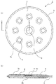
ここで、図1(a)は、本実施形態に係る誘導加熱発熱体の概略を示す上面図であり、図1(b)は、図1(a)のA−A断面図である。また、図7は、本実施形態に係る誘導加熱発熱体の一使用例を示す概略図である。
[First embodiment]
First, a first embodiment of the induction heating heating element according to the present invention will be described.
Here, FIG. 1A is a top view schematically showing the induction heating heating element according to the present embodiment, and FIG. 1B is a cross-sectional view taken along line AA of FIG. FIG. 7 is a schematic view showing an example of use of the induction heating heating element according to the present embodiment.
図1に示す発熱体1は、電磁調理器10などが備える電磁誘導加熱コイルから発生する高周波磁界により渦電流が誘起され、そのジュール熱により発熱する導電部材2を、導電部材2とほぼ同形状の封入部材3内に、熱伝導媒体4とともに封入して構成されている。そして、このような発熱体1は、例えば、図7に示すように、電磁調理器10により加熱対象物Mを加熱するに際して、このときに使用する容器11が非磁性材料からなるものであっても加熱対象物Mの加熱が可能となるように、容器11の底部に配置して使用することができる。
The heating element 1 shown in FIG. 1 has a
本実施形態の発熱体1を、このような電磁調理器10を用いた加熱調理用途に利用するにあたり、高周波磁界によって発熱する導電部材2は、容器11や、加熱対象物Mに直接触れることがなく、導電部材2が発する熱は、熱伝導媒体4を介して加熱対象物Mを加熱することになる。このため、導電部材2が発する熱によって容器11を損傷してしまったり、加熱対象物Mを焦がしてしまったりするというような不具合を有効に回避することができる。
When the heating element 1 of the present embodiment is used for heating cooking using such an electromagnetic cooker 10, the
このとき、加熱対象物Mが液状である場合は特に、発熱体1の裏面側、すなわち、発熱体1と容器11との間に加熱対象物Mが滞留するのを防止するために、発熱体1の任意の位置(図示する例では、ほぼ中央)に発熱体1を貫通する対流孔5を設け、発熱体1の裏面側と表面側との間で、加熱対象物Mが対流し易くなるようにしておくのが好ましく、これにより上記の不具合をより有効に回避することが可能となる。 At this time, particularly when the heating object M is in a liquid state, in order to prevent the heating object M from staying on the back side of the heating element 1, that is, between the heating element 1 and the container 11, the heating element. A convection hole 5 that penetrates the heating element 1 is provided at an arbitrary position 1 (substantially in the center in the illustrated example), and the heating object M is easily convected between the back surface side and the front surface side of the heating element 1. It is preferable to do so, and this makes it possible to avoid the above problems more effectively.
本実施形態において、熱伝導媒体4は、導電部材2に生じた熱を奪いつつ、発熱体1に接する加熱対象物Mに熱を伝えて加熱することができるものであればよい。本実施形態で使用可能な熱伝導媒体4に、特に制限はないが、導電部材2の局所的な温度上昇を避けるという観点から、封入部材3内を対流して、導電部材2の周囲から可能な限り均一に熱を奪う(冷却する)ことができるように、粘度の低い液状物であるのが好ましい。
In the present embodiment, the
より具体的には、水や、油類などを熱伝導媒体4として用いることができ、油類としては、封入部材3が破損するなどして漏れだした場合を考慮すると、大豆油、菜種油、オリーブオイル、米油、コーン油、べに花油、ごま油、パーム油、ひまし油、アボガド油、ココナッツ油、アーモンド油、クルミ油、はしばみ油などの食用油を一種又は二種以上混合して用いるのが好ましい。
More specifically, water, oils, etc. can be used as the
ここで、上記「液状物」の概念には、常温では固形状の物であっても、発熱体1を使用する際に、導電部材2の発熱により溶融して流動性を示すものも含まれるものとする。したがって、熱伝導媒体4に用いる液状物としては、導電部材2の発熱により、使用時に液状物となる常温で固形の食用動植物油脂などを一種又は二種以上混合して用いてもよく、これらを上記した食用油と混合して用いることもできる。
Here, the concept of the “liquid material” includes a material that is solid at room temperature and melts due to heat generated by the
また、熱伝導媒体4として、このような液状物を用いれば、熱伝導媒体4とともに封入されている導電部材2は、渦電流のつくる磁界により熱伝導媒体4中で浮き上がった状態となり、熱伝導媒体4が流動して導電部材2の下側に回り込んで導電部材2の下側における熱伝導媒体4の量が増大することとなるため、容器11の損傷をさらに有効に回避することができる。
Further, when such a liquid material is used as the
また、図1に示す例において、封入部材3は、導電部材2とほぼ同形状の表面材3aと、裏面材3bとからなる二枚のフィルム材を、導電部材2の外形形状に沿って周縁をヒートシールすることにより、導電部材2と熱伝導媒体4とを封入するようにしているが、封入部材3の具体的な形態に特に制限はない。例えば、封入部材3は、図1(c)に示すように、側面部に補助部材3cを用いてシールした形態としてもよく、また、特に図示しないが、封入部材3は方形の平袋状のものとしてもよく、導電部材2と熱伝導媒体4とを封入した状態で製袋することによって、発熱体1が形成されるようにすることもできる。
Further, in the example shown in FIG. 1, the encapsulating
なお、発熱体1を形成するにあたっては、例えば、先に導電部材2を入れた状態で封入部材3の一部に未シール部を残しておき、この未シール部から熱伝導媒体4を注入した後に未シール部をヒートシールすることにより、封入部材3を封止するなどすればよい。
In forming the heating element 1, for example, an unsealed portion is left in a part of the enclosing
本実施形態において、封入部材3に用いる素材は、導電部材2と熱伝導媒体4とを密封・封入することができるものであれば特に制限されない。例えば、ポリプロピレン,ポリエチレン等のポリオレフィン系樹脂;ナイロン等のポリアミド系樹脂;ポリエチレンテレフタレート等のポリエステル系樹脂などからなるフィルム材を単層で、又は二種以上を積層したものを用いることができる。
このような素材を用いて封入部材3を形成するに際し、封入部材3は、内部の状態を目視により確認できるように全部、又は一部を透明としてもよく、また、任意の印刷や着色を施して意匠性を付与したり、使用上の注意事項を記載したりするようにしてもよい。
In the present embodiment, the material used for the enclosing
When forming the encapsulating
また、本実施形態における導電部材2は、高周波磁界によって渦電流が誘起され、その電気抵抗によりジュール熱を発生するものであればよく、例えば、板状又は箔状の種々の金属素材を用いることができる。本実施形態において、導電部材2として利用可能な金属としては、例えば、アルミニウム,ニッケル,金,銀,銅,白金,鉄,コバルト,錫,亜鉛など、又はこれらの合金などを挙げることができる。
このような導電部材2の具体的な形状は特に制限されないが、高周波磁界により誘起される渦電流の流れを考慮すると、図示するような円板状とするのが好ましい。
In addition, the
Although the specific shape of such a
また、導電部材2には、特に、熱伝導媒体4として液状物を用いる場合に、封入部材3内での熱伝導媒体4の対流を促すことができるように、図2に示すような多数の内部対流孔2aを穿設しておくのが好ましい。これにより、導電部材2の周囲からよりいっそう均一に熱を奪って、導電部材2の局所的な温度上昇を抑制することができる。
なお、図2は、図1(b)において鎖線Bで囲む部分の拡大断面図である。
Further, in the case where a liquid material is used as the
2 is an enlarged cross-sectional view of a portion surrounded by a chain line B in FIG.
また、封入部材3内での熱伝導媒体4の対流を促すようことができるようにするためには、導電部材2は、上記したような構成とする代わりに、織布又は不織布からなる基材を用いて、その表面側と裏面側とを連通する多数の孔を残したまま、基材を形成する繊維の表面に、無電解メッキ又は塗布などの適宜手段により、上記した金属からなる導電被覆層を設けた構成とすることもできる。
In order to facilitate the convection of the
さらに、導電部材2には、図3(a)に示すように、任意の位置に切欠部2bを形成しておくことにより、導電部材2にヒューズ機能を付与することもできる。
すなわち、導電部材2の一部を切り欠くと、切り欠いた分だけ径方向に沿う断面積の総和が他の部分に比べて小さくなり、この部分の断面を流れる渦電流密度が高くなって発熱量が相対的に大きくなる部分が生じるため、導電部材2が一定以上の温度に発熱すると、このような意図的に発熱量が大きくなるようにされた部分が先に破損して、例えば、図3(b)に示すような亀裂2cが生じて渦電流の流れを阻止し、ヒューズとしての機能を発揮する。
Furthermore, as shown in FIG. 3A, the
That is, when a part of the
このように、導電部材2に切欠部2bを形成し、その形状や、切り欠く大きさなどを適宜調整することにより、伝導部材2が一定以上に加熱されるのを防止することができるが、このようなヒューズ機能は、同様の原理により、導電部材2の任意の位置を薄肉にすることによって実現することもでき、また、切欠部2bと、薄肉部との組み合わせによることもできる。
このとき、薄肉とする部分は、導電部材2の径方向に沿って形成するのが好ましく、これにより、渦電流の流れを阻止する亀裂2cが生じる方向を制御することができる。
Thus, by forming the
At this time, the thinned portion is preferably formed along the radial direction of the
[第二実施形態]
次に、本発明に係る誘導加熱発熱体の第二実施形態について説明する。
ここで、図4(a)は、本実施形態に係る誘導加熱発熱体の概略を示す上面図であり、図4(b)は、図4(a)のC−C断面図である。
[Second Embodiment]
Next, a second embodiment of the induction heating heating element according to the present invention will be described.
Here, FIG. 4A is a top view illustrating an outline of the induction heating heating element according to the present embodiment, and FIG. 4B is a cross-sectional view taken along the line C-C in FIG.
本実施形態が、前述した第一実施形態と異なるのは、封入部材3にガス抜き部を形成している点にある。
すなわち、熱伝導媒体4に液状物を用いる場合、特に、熱伝導媒体4に水を用いる場合には、加熱対象物Mの加熱温度は、通常、水の沸点付近となるため、加熱調理時に熱伝導媒体4である水が沸騰して内圧が上昇することにより、発熱体1(封入部材3)が破袋するなどの不具合が生じるおそれがあるが、本実施形態では、封入部材3形成されたにガス抜き部から蒸気を逃がして、発熱体1の内圧上昇を抑制できるようにしてある。
This embodiment is different from the first embodiment described above in that a degassing part is formed in the enclosing
That is, when a liquid material is used for the
このようなガス抜き部は、例えば、図4に示すように、封入部材3の任意の位置に一つ又は二以上のガス抜き孔6を穿設するとともに、気体(蒸気)の通過は許容するが、液体(水)は通過させない大きさの連通孔を多数有するシート材6aで、ガス抜き孔6を塞ぐことによって形成することができる。
For example, as shown in FIG. 4, such a gas venting part has one or two or more gas venting holes 6 formed at an arbitrary position of the enclosing
本実施形態が前述した第一実施形態と異なるのは、以上の点であり、それ以外は同様の構成を備えているので、他の構成についての詳細な説明は省略する。 This embodiment is different from the first embodiment described above in the above points, and the other configurations are the same as those in the first embodiment, and thus detailed description of other configurations is omitted.
[第三実施形態]
次に、本発明に係る誘導加熱発熱体の第三実施形態について説明する。
ここで、図5(a)は、本実施形態に係る誘導加熱発熱体の概略を示す上面図であり、図5(b)は、図5(a)のD−D断面図である。また、図6(a)は、本実施形態の変形例の概略を示す上面図であり、図6(b)は、図6(a)のE−E断面に相当する導電部材2の断面図である。
[Third embodiment]
Next, a third embodiment of the induction heating heating element according to the present invention will be described.
Here, Fig.5 (a) is a top view which shows the outline of the induction heating heating element which concerns on this embodiment, FIG.5 (b) is DD sectional drawing of Fig.5 (a). FIG. 6A is a top view schematically showing a modification of the present embodiment, and FIG. 6B is a cross-sectional view of the
前述した第一実施形態において、図1に示した例では、発熱体1のほぼ中央に一つの対流孔5を設けているが、本実施形態として図5に示す例にあっては、発熱体1のほぼ中央に対流孔5aを設けるとともに、この対流孔5aを中心とする周囲に、四つの対流孔5bをほぼ等間隔に設けることによって、発熱体1の裏面側と表面側との間における加熱対象物Mの対流が、より容易に生じるようにしてある。
In the first embodiment described above, in the example shown in FIG. 1, one convection hole 5 is provided at substantially the center of the heating element 1, but in the example shown in FIG. 5 as this embodiment, the heating element. 1 is provided at approximately the center of the
本実施形態において、対流孔5(5a,5b)の数や、その設ける位置は任意であり、図示する例には限られないが、発熱体1のほぼ中央以外の部位に対流孔5(5b)を設けると、第一実施形態において切欠部2bを形成する場合と同様に、対流孔5bを設けた部分における径方向に沿う断面積の総和が他の部分に比べて小さくなり、この部分の断面を流れる渦電流密度が高くなって発熱量が相対的に大きくなる。
切欠部2bなどを形成する代わりに、対流孔5bを設けることによっても導電部材2にヒューズ機能を付与することが可能であるが、ヒューズ機能を付与するための切欠部2bを別途形成する場合などには、対流孔5bを設けることによる発熱量の部分的な増大に対処する必要がある。
In the present embodiment, the number of convection holes 5 (5a, 5b) and the positions of the convection holes 5 are not limited to the illustrated example, but the convection holes 5 (5b) ), As in the case of forming the
It is possible to provide the
本実施形態は、このような対流孔5bを設けたことに伴う発熱量の部分的な増大による発熱体1の破損を防止するものである。
すなわち、図示するように、導電部材2の中心に対して同心円上に対流孔5bを設けると、一般には、対流孔5bを設けた部位において径方向に沿った、導電部材2の外径側の対流孔5bの縁部や、導電部材2の外周縁部で、発熱量が増大する傾向があるが、本実施形態は、このような発熱量の増大による発熱体1の破損を防止する。
In the present embodiment, the heating element 1 is prevented from being damaged due to a partial increase in the amount of heat generated by providing such a
That is, as shown in the figure, when the
本実施形態では、上記した発熱量が増大する傾向にある部位(図5(a)中鎖線で囲む部位)において、封入部材3の裏面側の基材フィルム3bの内面に断熱部7を形成し、封入部材3の破損や、発熱体1の局所的な温度上昇を防止するようにしてある。
封入部材3に形成する断熱部7は、例えば、封入部材3を形成するフィルム基材3bの肉厚を他の部分に対して厚肉とすることによって形成することができるが、封入部材3と同種又は異種のフィルム材や、その他の補強部材を、相当する部位に貼着することにより形成するのが、製造上容易であるため好ましい。
In the present embodiment, the heat insulating portion 7 is formed on the inner surface of the
The heat insulating portion 7 formed on the encapsulating
また、本実施形態は、図6に示すように変形実施することもできる。図6に示す変形例では、図6(a)中斜線で示す部分を導電部材2の肉厚を変化させた厚肉部2dとし、渦電流の流れ方向に直交する導電部材2の断面積がほぼ一定となるようにしており、これにより渦電流密度を均一化して、導電部材2の局所的な温度上昇が生じないようにしてある。
Further, the present embodiment can be modified as shown in FIG. In the modification shown in FIG. 6, the portion shown by the oblique line in FIG. 6 (a) is the thick portion 2d in which the thickness of the
本実施形態が前述した第一実施形態と異なるのは、以上の点であり、それ以外は同様の構成を備えているので、他の構成についての詳細な説明は省略する。 This embodiment is different from the first embodiment described above in the above points, and the other configurations are the same as those in the first embodiment, and thus detailed description of other configurations is omitted.
以上、本発明について、好ましい実施形態を示して説明したが、本発明は、上記した実施形態にのみ限定されるものではなく、本発明の範囲で種々の変更実施が可能であることは言うまでもない。 While the present invention has been described with reference to the preferred embodiment, it is needless to say that the present invention is not limited to the above-described embodiment, and various modifications can be made within the scope of the present invention. .
例えば、上記した実施形態では、発熱体1を円形状としたものを例に挙げたが、発熱体1の形状は、使用する容器11の底部の形状などに応じて種々の形状を採用することができる。また、使用する容器11の底部の形状が円形状であっても、発熱体1を方形にして、その四隅を容器11の側壁に沿わせるように立ち上がらせた状態で、発熱体1を容器11の底部に配置して使用することもできる。
このとき、導電部材2の形状も方形としてもよく、導電部材2の一部を容器11の側壁に沿わせるようにすることで、加熱対象物Mを容器11の側壁側から加熱することも可能となる。
For example, in the above-described embodiment, the heating element 1 having a circular shape is taken as an example. However, the heating element 1 may have various shapes depending on the shape of the bottom of the container 11 to be used. Can do. Even if the shape of the bottom portion of the container 11 to be used is circular, the heating element 1 is placed in a state in which the heating element 1 is square and the four corners thereof are raised along the side walls of the container 11. It is also possible to use it by arranging it at the bottom.
At this time, the shape of the
また、導電部材2には、必要に応じて断熱層を設けることもでき、これにより、封入部材3に与える熱の影響を緩和するようにしてもよい。このとき、断熱層は、導電部材2の裏面側に設けるのが好ましいが、加熱対象物Mを加熱する際の熱効率を阻害しない範囲で、導電部材2の表面側に設けてもよい。
Further, the
また、本発明に係る誘導加熱容器は、上記したような発熱体1を備えて構成され、発熱体1は、通常、容器底部に配置されるように取り付けられるが、このとき、発熱体1側、容器側のいずれか一方、又は両方に、廃棄処理時に分別が容易となるような固定用のつめなどの任意の取り付け手段を設けておくことができる。 In addition, the induction heating container according to the present invention is configured to include the heating element 1 as described above, and the heating element 1 is usually mounted so as to be disposed at the bottom of the container. Any one or both of the container side may be provided with any attachment means such as a fixing claw that facilitates separation during disposal.
このような本発明に係る誘導加熱容器にあっては、その容器本体が、電磁誘導によって発熱する導電部材2と直接接することがなく、導電部材2が発する熱による容器本体の損傷を考慮する必要がないため、容器本体を形成する材料には、耐熱性などの特性が要求されることがない。したがって、例えば、従来の即席食品用の容器として、広く用いられている発泡ポリスチレンなどの汎用の非磁性材料にて容器本体を形成することにより、電磁調理器で使用可能な低コストの容器を容易に提供することができる。
In such an induction heating container according to the present invention, the container body does not directly contact the
以上説明したように、本発明は、専用の調理器具を用いる必要がある電磁調理器の不利を解消し、非磁性材料からなる容器を用いても加熱対象物を加熱することができるのみならず、使用する容器の損傷や、加熱対象物の焦げつきなどを防止することができる汎用性に優れた誘導加熱発熱体、及びそのような誘導加熱発熱体を備えた誘導加熱容器を提供する。 As described above, the present invention eliminates the disadvantages of an electromagnetic cooker that requires the use of a dedicated cooking utensil, and can not only heat a heating object even using a container made of a non-magnetic material. The present invention provides an induction heating heating element excellent in versatility capable of preventing damage to a container to be used and burning of an object to be heated, and an induction heating container provided with such an induction heating heating element.
1 発熱体
2 導電部材
2a 内部対流孔
2b 切欠部
3 封入部材
4 熱伝導媒体
5 対流孔
6 ガス抜き孔
7 断熱部
10 電磁調理器
11 容器
M 加熱対象物
DESCRIPTION OF SYMBOLS 1
Claims (12)
前記導電部材の周囲を覆う熱伝導媒体とともに、
封入部材内に封入してなることを特徴とする誘導加熱発熱体。 A conductive member that generates heat when an eddy current is induced by a high-frequency magnetic field,
Together with a heat conductive medium covering the periphery of the conductive member,
An induction heating heating element characterized by being enclosed in an enclosing member.
Priority Applications (1)
| Application Number | Priority Date | Filing Date | Title |
|---|---|---|---|
| JP2005159142A JP4665610B2 (en) | 2005-05-31 | 2005-05-31 | Induction heating heating element and induction heating container |
Applications Claiming Priority (1)
| Application Number | Priority Date | Filing Date | Title |
|---|---|---|---|
| JP2005159142A JP4665610B2 (en) | 2005-05-31 | 2005-05-31 | Induction heating heating element and induction heating container |
Publications (2)
| Publication Number | Publication Date |
|---|---|
| JP2006338902A true JP2006338902A (en) | 2006-12-14 |
| JP4665610B2 JP4665610B2 (en) | 2011-04-06 |
Family
ID=37559294
Family Applications (1)
| Application Number | Title | Priority Date | Filing Date |
|---|---|---|---|
| JP2005159142A Expired - Fee Related JP4665610B2 (en) | 2005-05-31 | 2005-05-31 | Induction heating heating element and induction heating container |
Country Status (1)
| Country | Link |
|---|---|
| JP (1) | JP4665610B2 (en) |
Cited By (2)
| Publication number | Priority date | Publication date | Assignee | Title |
|---|---|---|---|---|
| CN106247414A (en) * | 2016-07-28 | 2016-12-21 | 杭州信多达电器有限公司 | Low-radiation induction cooker magnetic stripe arrangement structure |
| CN114074406A (en) * | 2020-08-18 | 2022-02-22 | 苏州亮福电器有限公司 | Highlight injection mold adopting electric heating mode |
Citations (4)
| Publication number | Priority date | Publication date | Assignee | Title |
|---|---|---|---|---|
| JPS5270444A (en) * | 1975-12-10 | 1977-06-11 | Mitsubishi Electric Corp | Induction heater |
| JPH0361234U (en) * | 1989-10-16 | 1991-06-17 | ||
| JPH059418U (en) * | 1991-07-12 | 1993-02-09 | 広島アルミニウム工業株式会社 | Heater for electromagnetic hob |
| JP2000311773A (en) * | 1999-04-27 | 2000-11-07 | Hakko Denki Kk | Induction heating tools |
-
2005
- 2005-05-31 JP JP2005159142A patent/JP4665610B2/en not_active Expired - Fee Related
Patent Citations (4)
| Publication number | Priority date | Publication date | Assignee | Title |
|---|---|---|---|---|
| JPS5270444A (en) * | 1975-12-10 | 1977-06-11 | Mitsubishi Electric Corp | Induction heater |
| JPH0361234U (en) * | 1989-10-16 | 1991-06-17 | ||
| JPH059418U (en) * | 1991-07-12 | 1993-02-09 | 広島アルミニウム工業株式会社 | Heater for electromagnetic hob |
| JP2000311773A (en) * | 1999-04-27 | 2000-11-07 | Hakko Denki Kk | Induction heating tools |
Cited By (3)
| Publication number | Priority date | Publication date | Assignee | Title |
|---|---|---|---|---|
| CN106247414A (en) * | 2016-07-28 | 2016-12-21 | 杭州信多达电器有限公司 | Low-radiation induction cooker magnetic stripe arrangement structure |
| CN114074406A (en) * | 2020-08-18 | 2022-02-22 | 苏州亮福电器有限公司 | Highlight injection mold adopting electric heating mode |
| CN114074406B (en) * | 2020-08-18 | 2024-02-27 | 苏州亮福电器有限公司 | High-gloss injection mold adopting electric heating mode |
Also Published As
| Publication number | Publication date |
|---|---|
| JP4665610B2 (en) | 2011-04-06 |
Similar Documents
| Publication | Publication Date | Title |
|---|---|---|
| CN104619216B (en) | Induction Heating Vessels | |
| JPWO2012132284A1 (en) | Induction heating heating element, manufacturing method thereof, and induction heating container | |
| JP4665610B2 (en) | Induction heating heating element and induction heating container | |
| JP3654249B2 (en) | rice cooker | |
| US20150083730A1 (en) | Dual pot | |
| JP6248744B2 (en) | Induction heating rice cooker | |
| JP2009045255A (en) | Electric cooker container | |
| JP5138468B2 (en) | Induction heating heating element and induction heating container | |
| JP2012110636A (en) | Cooking container for induction-heating cooker | |
| JP2004000379A (en) | Aluminum container for heating | |
| JP4826345B2 (en) | Packaging container | |
| JP2007296040A (en) | Electromagnetic cookable standing pouch | |
| JP6115325B2 (en) | Induction heating heating tool | |
| JP2006312007A (en) | Cooking container | |
| JP5253938B2 (en) | Induction heating vessel | |
| JP2014033901A (en) | Heat cooker | |
| JP4872537B2 (en) | Induction heating cooking container | |
| JP4722020B2 (en) | Electromagnetic induction heating cooker | |
| JP2008220470A (en) | Electric rice cooker | |
| JP5954482B1 (en) | Induction heating heating element and induction heating container | |
| JP2007222402A (en) | Heating container and inner tray, and heating method using electromagnetic cooker | |
| JP2006185752A (en) | Container for electromagnetic cooker | |
| JP4807151B2 (en) | Induction heating cooking container | |
| JP2010214032A (en) | Rice cooker with warmer | |
| JP4992307B2 (en) | Electric rice cooker |
Legal Events
| Date | Code | Title | Description |
|---|---|---|---|
| A621 | Written request for application examination |
Free format text: JAPANESE INTERMEDIATE CODE: A621 Effective date: 20080410 |
|
| A977 | Report on retrieval |
Free format text: JAPANESE INTERMEDIATE CODE: A971007 Effective date: 20100210 |
|
| A131 | Notification of reasons for refusal |
Free format text: JAPANESE INTERMEDIATE CODE: A131 Effective date: 20100406 |
|
| A521 | Written amendment |
Free format text: JAPANESE INTERMEDIATE CODE: A523 Effective date: 20100604 |
|
| TRDD | Decision of grant or rejection written | ||
| A01 | Written decision to grant a patent or to grant a registration (utility model) |
Free format text: JAPANESE INTERMEDIATE CODE: A01 Effective date: 20101214 |
|
| A01 | Written decision to grant a patent or to grant a registration (utility model) |
Free format text: JAPANESE INTERMEDIATE CODE: A01 |
|
| A61 | First payment of annual fees (during grant procedure) |
Free format text: JAPANESE INTERMEDIATE CODE: A61 Effective date: 20101227 |
|
| FPAY | Renewal fee payment (event date is renewal date of database) |
Free format text: PAYMENT UNTIL: 20140121 Year of fee payment: 3 |
|
| R150 | Certificate of patent or registration of utility model |
Ref document number: 4665610 Country of ref document: JP Free format text: JAPANESE INTERMEDIATE CODE: R150 Free format text: JAPANESE INTERMEDIATE CODE: R150 |
|
| FPAY | Renewal fee payment (event date is renewal date of database) |
Free format text: PAYMENT UNTIL: 20140121 Year of fee payment: 3 |
|
| S531 | Written request for registration of change of domicile |
Free format text: JAPANESE INTERMEDIATE CODE: R313531 |
|
| FPAY | Renewal fee payment (event date is renewal date of database) |
Free format text: PAYMENT UNTIL: 20140121 Year of fee payment: 3 |
|
| R350 | Written notification of registration of transfer |
Free format text: JAPANESE INTERMEDIATE CODE: R350 |
|
| S533 | Written request for registration of change of name |
Free format text: JAPANESE INTERMEDIATE CODE: R313533 |
|
| FPAY | Renewal fee payment (event date is renewal date of database) |
Free format text: PAYMENT UNTIL: 20140121 Year of fee payment: 3 |
|
| R350 | Written notification of registration of transfer |
Free format text: JAPANESE INTERMEDIATE CODE: R350 |
|
| LAPS | Cancellation because of no payment of annual fees |