JP2006347314A - Automatic transmission shift device - Google Patents
Automatic transmission shift device Download PDFInfo
- Publication number
- JP2006347314A JP2006347314A JP2005174844A JP2005174844A JP2006347314A JP 2006347314 A JP2006347314 A JP 2006347314A JP 2005174844 A JP2005174844 A JP 2005174844A JP 2005174844 A JP2005174844 A JP 2005174844A JP 2006347314 A JP2006347314 A JP 2006347314A
- Authority
- JP
- Japan
- Prior art keywords
- shift
- pole
- sensor
- magnet plate
- flux density
- Prior art date
- Legal status (The legal status is an assumption and is not a legal conclusion. Google has not performed a legal analysis and makes no representation as to the accuracy of the status listed.)
- Granted
Links
Images


Classifications
-
- F—MECHANICAL ENGINEERING; LIGHTING; HEATING; WEAPONS; BLASTING
- F16—ENGINEERING ELEMENTS AND UNITS; GENERAL MEASURES FOR PRODUCING AND MAINTAINING EFFECTIVE FUNCTIONING OF MACHINES OR INSTALLATIONS; THERMAL INSULATION IN GENERAL
- F16H—GEARING
- F16H59/00—Control inputs to control units of change-speed- or reversing-gearings for conveying rotary motion
- F16H59/02—Selector apparatus
- F16H59/08—Range selector apparatus
- F16H59/10—Range selector apparatus comprising levers
- F16H59/105—Range selector apparatus comprising levers consisting of electrical switches or sensors
-
- Y—GENERAL TAGGING OF NEW TECHNOLOGICAL DEVELOPMENTS; GENERAL TAGGING OF CROSS-SECTIONAL TECHNOLOGIES SPANNING OVER SEVERAL SECTIONS OF THE IPC; TECHNICAL SUBJECTS COVERED BY FORMER USPC CROSS-REFERENCE ART COLLECTIONS [XRACs] AND DIGESTS
- Y10—TECHNICAL SUBJECTS COVERED BY FORMER USPC
- Y10T—TECHNICAL SUBJECTS COVERED BY FORMER US CLASSIFICATION
- Y10T74/00—Machine element or mechanism
- Y10T74/19—Gearing
- Y10T74/19219—Interchangeably locked
- Y10T74/19251—Control mechanism
-
- Y—GENERAL TAGGING OF NEW TECHNOLOGICAL DEVELOPMENTS; GENERAL TAGGING OF CROSS-SECTIONAL TECHNOLOGIES SPANNING OVER SEVERAL SECTIONS OF THE IPC; TECHNICAL SUBJECTS COVERED BY FORMER USPC CROSS-REFERENCE ART COLLECTIONS [XRACs] AND DIGESTS
- Y10—TECHNICAL SUBJECTS COVERED BY FORMER USPC
- Y10T—TECHNICAL SUBJECTS COVERED BY FORMER US CLASSIFICATION
- Y10T74/00—Machine element or mechanism
- Y10T74/20—Control lever and linkage systems
- Y10T74/20012—Multiple controlled elements
- Y10T74/20018—Transmission control
Landscapes
- Engineering & Computer Science (AREA)
- General Engineering & Computer Science (AREA)
- Mechanical Engineering (AREA)
- Arrangement Or Mounting Of Control Devices For Change-Speed Gearing (AREA)
Abstract
【課題】 少ないセンサ数で冗長性を確保しつつシフト位置の検知を行うことができる自動変速機のシフト装置を提供する。
【解決手段】 シフト装置のシフト位置検知装置13は、シフトレバー10の下端部にこのシフトレバー10のシフト操作に応じて移動自在に設置した、複数の平板状のマグネットをN極とS極が隣接するようにして配置して構成された多極マグネット板15と、この多極マグネット板15のシフトレバー10と反対側に各シフト位置に基づいて所定位置に非接触で複数配置した、検出した磁束密度の強弱に応じてON/OFF信号を出力するON・OFFセンサ(S1,S3)と、検出した磁束密度の大きさに応じた出力値を出力するリニアセンサ(R2)とを備えている。
【選択図】 図3PROBLEM TO BE SOLVED: To provide a shift device for an automatic transmission capable of detecting a shift position while ensuring redundancy with a small number of sensors.
A shift position detecting device 13 of a shift device includes a plurality of plate-shaped magnets, which are arranged at the lower end portion of a shift lever 10 so as to be movable according to a shift operation of the shift lever 10, and have N and S poles. A multi-pole magnet plate 15 arranged so as to be adjacent to each other, and a plurality of non-contact arrangements at predetermined positions based on the respective shift positions on the side opposite to the shift lever 10 of the multi-pole magnet plate 15 is detected. An ON / OFF sensor (S1, S3) that outputs an ON / OFF signal according to the strength of the magnetic flux density and a linear sensor (R2) that outputs an output value according to the magnitude of the detected magnetic flux density are provided. .
[Selection] Figure 3
Description
本発明は、車両に搭載される自動変速機のシフト装置に関する。 The present invention relates to a shift device for an automatic transmission mounted on a vehicle.
車両に搭載される自動変速機のシフト装置として、近年、装置の小型化や操作力の低減化において有利な、いわゆるシフト・バイ・ワイヤ方式のシフト装置が提案されている。シフト・バイ・ワイヤ方式のシフト装置は、運転者がシフトレバーを操作したときのシフト位置をセンサによって検知し、その検知信号に基づいてアクチュエータで自動変速機(オートマチック・トランスミッション:以下、ATという)のレンジを切り替える、つまり電気的制御によりATのレンジを切り替える構成となっている(例えば、特許文献1参照)。
ところで、前記特許文献1のシフト装置では、シフトレバーの4つのシフト位置(N(ニュートラル)、R(リバース)、D(ドライブ)、+(シフトアップ)、−(シフトダウン))に対応して4つのセンサを配置しているが、このようなセンサ配置では、いずれかのセンサに不具合等が発生してセンサ信号が出力されなくなると、そのシフトポジションにシフト操作したときに、そのシフトポジションに対応したATのレンジの切り替えができなくなってしまう。
By the way, in the shift device of the above-mentioned
このため、冗長性を持たせるために、各シフト位置にそれぞれ2つ以上のセンサを配置して、仮に一方のセンサに不具合等が発生した場合でも、確実にセンサ信号を出力できるようにする構成が考えられるが、この場合、センサの数が少なくとも2倍以上に増えるため、コストが高くなってしまう。 For this reason, in order to provide redundancy, two or more sensors are arranged at each shift position, so that even if a malfunction occurs in one of the sensors, the sensor signal can be reliably output. However, in this case, the number of sensors is increased by at least twice, which increases the cost.
そこで、本発明は、少ないセンサ数で冗長性を確保しつつシフト位置の検知を行うことができる自動変速機のシフト装置を提供することを目的とする。 Therefore, an object of the present invention is to provide a shift device for an automatic transmission that can detect a shift position while ensuring redundancy with a small number of sensors.
前記目的を達成するために本発明は、シフト溝に沿って複数のシフト位置に揺動自在に支持されたシフトレバーと、前記シフトレバーを操作したときのシフト位置を検知するシフト位置検知手段とを有する自動変速機のシフト装置において、前記シフト位置検知手段は、前記シフトレバーの下端部にこのシフトレバーのシフト操作に応じて移動自在に設置されたマグネット板と、前記マグネット板の前記シフトレバーと反対側に、前記各シフト位置に基づいて所定位置に非接触で複数配置され、前記マグネット板に対して磁束密度を検出し、検出した磁束密度の強弱に応じてON/OFF信号を出力する第1の磁気センサと、前記マグネット板の前記シフトレバーと反対側に、前記各シフト位置に基づいて所定位置に非接触で少なくとも1個配置され、前記マグネット板に対して磁束密度を検出し、検出した磁束密度の大きさに応じた出力値を出力する第2の磁気センサと、を備えていることを特徴としている。 In order to achieve the above object, the present invention provides a shift lever that is swingably supported at a plurality of shift positions along a shift groove, and a shift position detecting means that detects a shift position when the shift lever is operated. In the shift device for an automatic transmission, the shift position detecting means includes a magnet plate that is movably installed at a lower end portion of the shift lever according to a shift operation of the shift lever, and the shift lever of the magnet plate. On the opposite side, a plurality of non-contact arrangements are made at predetermined positions based on the respective shift positions, the magnetic flux density is detected with respect to the magnet plate, and an ON / OFF signal is output according to the strength of the detected magnetic flux density. On the opposite side of the first magnetic sensor and the shift lever of the magnet plate, at least one non-contact at a predetermined position based on each shift position Is location, it detects the magnetic flux density to the magnet plate, and a second magnetic sensor that outputs an output value corresponding to the magnitude of the detected magnetic flux density, characterized in that it comprises a.
請求項1に記載の発明によれば、第1の磁気センサは、シフト操作時におけるシフト位置に応じて検出した磁束密度の強弱に応じてON/OFF信号を出力し、第2の磁気センサは、シフト操作時におけるシフト位置に応じて検出した磁束密度の大きさに応じた出力値を出力することにより、第1の磁気センサと第2の磁気センサからの各センサ出力(センサ信号)に基づいてシフト位置を検知することができる。 According to the first aspect of the invention, the first magnetic sensor outputs an ON / OFF signal according to the strength of the magnetic flux density detected according to the shift position during the shift operation, and the second magnetic sensor Based on each sensor output (sensor signal) from the first magnetic sensor and the second magnetic sensor by outputting an output value corresponding to the magnitude of the magnetic flux density detected according to the shift position during the shift operation. The shift position can be detected.
また、請求項2に記載の発明は、前記マグネット板を、複数の平板状のマグネットをN極とS極が隣接するように配置して形成された多極マグネット板とし、前記第1の磁気センサを、前記N極における検出特性と前記S極における検出特性との変化を検出した場合にON信号もしくはOFF信号を出力するセンサとし、前記第2の磁気センサを、前記多極マグネット板のN極もしくはS極に対して磁束密度を検出し、検出した磁束密度の大きさに応じた出力値を出力するセンサとしたことを特徴としている。 According to a second aspect of the present invention, the magnet plate is a multi-pole magnet plate formed by arranging a plurality of flat magnets so that the N pole and the S pole are adjacent to each other. The sensor is a sensor that outputs an ON signal or an OFF signal when a change between the detection characteristic at the N pole and the detection characteristic at the S pole is detected, and the second magnetic sensor is the N pole of the multipole magnet plate. The sensor is characterized by detecting the magnetic flux density with respect to the pole or the S pole and outputting an output value corresponding to the magnitude of the detected magnetic flux density.
請求項2に記載の発明によれば、マグネット板を、複数の平板状のマグネットをN極とS極が隣接するように配置して形成された多極マグネット板として、第1の磁気センサで、多極マグネット板の移動に伴うN極とS極の移り変わりを検出することにより、N極もしくはS極のどちらか一方における磁束密度の強弱に応じてON/OFF信号を出力する場合よりも、磁束のばらつきが抑制され、より安定してON/OFF信号を出力することができる。 According to the second aspect of the present invention, the magnet plate is a multi-pole magnet plate formed by arranging a plurality of flat magnets so that the N pole and the S pole are adjacent to each other. By detecting the transition between the N pole and the S pole accompanying the movement of the multipole magnet plate, the ON / OFF signal is output according to the strength of the magnetic flux density at either the N pole or the S pole. Variation in magnetic flux is suppressed, and an ON / OFF signal can be output more stably.
請求項1に記載の発明によれば、第1の磁気センサは、シフト操作時におけるシフト位置に応じて検出した磁束密度の強弱に応じてON/OFF信号の2つのセンサ出力を出力する。また、第2の磁気センサは、シフト操作時におけるシフト位置に応じて検出した磁束密度の変化に応じて出力値を出力することにより、この出力値を任意の閾値で区切ることによって複数の異なるセンサ出力が得られる。よって、複数の第1の磁気センサと少なくとも1つの第2の磁気センサを、マグネット板と対向するようにしてそれぞれ所定位置に配置する配置することにより、少ないセンサ数で冗長性を確保しつつシフト位置の検知を行うことができる。 According to the first aspect of the invention, the first magnetic sensor outputs two sensor outputs of the ON / OFF signal according to the strength of the magnetic flux density detected according to the shift position during the shift operation. Further, the second magnetic sensor outputs an output value according to a change in magnetic flux density detected according to the shift position at the time of the shift operation, and a plurality of different sensors are separated by dividing the output value by an arbitrary threshold value. Output is obtained. Therefore, a plurality of first magnetic sensors and at least one second magnetic sensor are arranged at predetermined positions so as to face the magnet plate, thereby shifting while ensuring redundancy with a small number of sensors. Position detection can be performed.
また、請求項2に記載の発明によれば、第1の磁気センサからより精度よくON/OFF信号を出力することができるので、シフト位置をより安定して検知することができる。 According to the second aspect of the invention, since the ON / OFF signal can be output from the first magnetic sensor with higher accuracy, the shift position can be detected more stably.
以下、本発明を図示の実施形態に基づいて説明する。図1は、本発明の実施形態に係る自動変速機のシフト装置を示す概略構成図、図2は、本発明の実施形態に係るシフト装置を示す概略斜視図、図3は、本発明の実施形態に係るシフト装置を示す概略断面図である。 Hereinafter, the present invention will be described based on the illustrated embodiments. 1 is a schematic configuration diagram showing a shift device of an automatic transmission according to an embodiment of the present invention, FIG. 2 is a schematic perspective view showing a shift device according to an embodiment of the present invention, and FIG. 3 is an embodiment of the present invention. It is a schematic sectional drawing which shows the shift apparatus which concerns on a form.
図1に示すように、AT(自動変速機)1には、制御装置(ECU)2を介してシフト装置3が電気的に接続されている。AT1は、トルクコンバータ4を介してエンジン5のエンジン出力軸(不図示)に連結されている。AT1の油圧制御部6には、AT1のレンジ切り替えを行うための電動アクチュエータ6aが設けられている。油圧制御部6および電動アクチュエータ6aは、制御装置2からの制御信号に基づいて駆動制御される。
As shown in FIG. 1, a
制御装置2は、車室内に設けられたシフト・バイ・ワイヤ方式のシフト装置3と電気的に接続されており、シフト装置3のシフトレバー10(図2参照)のシフト位置に応じた検知信号(センサ信号)が、後記するシフト位置検知装置13から制御装置2に入力される。制御装置2は、シフト装置3のシフト位置検知装置13から入力される検知信号に基づいて、油圧制御部6および電動アクチュエータ6aに制御信号を出力して両者を駆動制御する。
The control device 2 is electrically connected to a shift-by-
AT1のシフトレンジは、本実施形態ではP(パーキング)レンジ、R(リバース)レンジ、N(ニュートラル)レンジ、D(ドライブ)レンジ、L(ロー)レンジを有しており、各レンジの配列はPレンジ、Rレンジ、Nレンジ、Dレンジ、Lレンジの順に設定されている。なお、AT1がNレンジに選択された場合は、AT1のエンジン5側と駆動輪(不図示)側との動力伝達を遮断した中立状態に設定され、また、Pレンジに選択された場合は、エンジン5側と駆動輪(不図示)側との動力伝達を遮断した中立状態に設定されるとともに、パーキングロック機構(不図示)が作動してAT1の出力軸7を機械的にロックする。 In this embodiment, the shift range of AT1 has a P (parking) range, an R (reverse) range, an N (neutral) range, a D (drive) range, and an L (low) range. P range, R range, N range, D range, and L range are set in this order. When AT1 is selected for the N range, it is set to a neutral state in which the power transmission between the engine 5 side and the drive wheel (not shown) side of AT1 is cut off, and when it is selected for the P range, A neutral state in which power transmission between the engine 5 side and the drive wheel (not shown) side is cut off is set, and a parking lock mechanism (not shown) is activated to mechanically lock the output shaft 7 of AT1.
図2に示すように、シフト装置3には、上カバー8aにシフトパターンを形成するゲート溝9が設けられており、このゲート溝9にはシフトレバー10が挿通されている。なお、シフト装置3は、例えば運転席近傍のフロア(不図示)上に設置されている。
As shown in FIG. 2, the
ゲート溝9は、車両の前後方向に沿って延びる直線状の第1ゲート溝9aと、この第1ゲート溝9aの前端(図2の右上側)から右側に向けて形成した第2ゲート溝9bと、この第1ゲート溝9aの後端(図2の左下側)から左側に向けて形成した第3ゲート溝9cを有しており、第1ゲート溝9aの前端(図2の右上側)近傍がN(ニュートラル)位置、第1ゲート溝9aの後端(図2の左下側)近傍がD(ドライブ)位置、第2ゲート溝9b内がR(リバース)位置、第3ゲート溝9c内がL(ロー)位置である。ゲート溝9の周囲には、前記R、N、D、Lの各位置に合わせて「R」、「N」、「D」、「L」の記号が付されている。なお、ゲート溝9のR、N、D、Lの各位置は、前記AT1のRレンジ、Nレンジ、Dレンジ、Lレンジにそれぞれ対応している。
The gate groove 9 includes a linear
また、上カバー8aの前端側(図2の右上側)には、プッシュボタン方式のP(パーキング)操作ボタン11が設けられている。
Further, a push button type P (parking)
シフト装置3のケース本体8b内には、シフトレバー10をゲート溝9(第1ゲート溝9a、第2ゲート溝9b、第3ゲート溝9c)に沿って揺動自在に支持する支持機構(不図示)と、シフトレバー10を第1ゲート溝9a内のN位置もしくはD位置のいずれかに操作した後に手を放すことにより、中立位置(ホームポジション:以下、H位置という)12に自動的に復帰させる復帰機構(不図示)が設けられている。なお、このとき、シフトレバー10がH位置12に復帰した状態でも、AT1はNレンジもしくはDレンジに保持されている。
In the case
シフトレバー10をR位置である第2ゲート溝9b内に入れたとき、およびシフトレバー10をL位置である第3ゲート溝9c内に入れたときには、ディテント機構(不図示)によってその位置に保持するように構成されている。この保持解除は、シフトレバー10を第1ゲート溝9a側に手で押して戻すことで行うことができる。なお、P操作ボタン11を押すP(パーキング)時には、シフトレバー10はH位置12に位置している。
When the
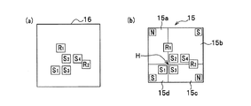
また、図2、図3に示すように、シフト装置3のケース本体8b内には、シフトレバー10の操作によるシフト位置(シフトポジション)を検知するためのシフト位置検知装置13が設けられている。シフト位置検知装置13は、図3に示すように、マグネット支持部材14の凹状部内に固定保持された四角形状の多極マグネット板15と、多極マグネット板15の下方(図3の下側)にこの多極マグネット板15と対向するように配置した四角形状の基板16と、この基板16の表面(多極マグネット板15側の表面)に配置した複数(本実施形態では4つ)のON/OFFセンサS1,S2,S3およびS4(図4(a)参照)と、複数(本実施形態では2つ)のリニアセンサR1,R2(図4(a)参照)を備えている。
As shown in FIGS. 2 and 3, a shift
図3に示すように、マグネット支持部材14の上面に設けた連結部14aにはシフトレバー10の下端部が連結されており、ガイド部材17の下面に対して摺動自在に設置されたマグネット支持部材14の内側の多極マグネット板15は、シフトレバー10のシフト操作に応じて基板16に対してほぼ平行状態で移動自在である。
As shown in FIG. 3, the lower end portion of the
図4(a)に示すように、ON・OFFセンサS1,S3、およびON・OFFセンサS2,S4は、それぞれ車幅方向(図の左右方向)に沿って近接して配置され、かつON・OFFセンサS2は、車両の前後方向(図の上下方向)に対してON・OFFセンサS3の前方側に近接して配置されている。また、リニアセンサR1は、車両の前後方向(図の上下方向)に対してON・OFFセンサS2の左斜め前方側に近接して配置されており、リニアセンサR2は、車幅方向(図の左右方向)に対してON・OFFセンサS4の右斜め後方側に接して配置されている。 As shown in FIG. 4 (a), the ON / OFF sensors S1, S3 and the ON / OFF sensors S2, S4 are arranged close to each other along the vehicle width direction (left-right direction in the figure), and The OFF sensor S2 is disposed close to the front side of the ON / OFF sensor S3 with respect to the longitudinal direction of the vehicle (the vertical direction in the figure). The linear sensor R1 is disposed close to the left front side of the ON / OFF sensor S2 with respect to the longitudinal direction of the vehicle (the vertical direction in the figure). The linear sensor R2 is arranged in the vehicle width direction (in the figure). (On the left and right directions), the ON / OFF sensor S4 is disposed in contact with the diagonally right rear side.
図4(b)に示すように、多極マグネット板15は、基板16側から見て右回りに四角形状の4つのマグネット15a,15b,15c,15dのそれぞれの一角部が一点でほぼ接するようにしてマグネット支持部材14に接着されている。板状で四角形状の各マグネット15a〜15dは、それぞれ基板16側にN極、S極、N極、S極が面するようにして配置されている。なお、図4(b)は、シフトレバー10がH位置(図の矢印位置)における多極マグネット板15の各マグネット15a〜15dと、基板16上の各センサ(ON・OFFセンサS1,S2,S3,S4、リニアセンサR1,R2)との対応位置関係を示している。
As shown in FIG. 4B, the
すなわち、本実施形態では、図4(b)に示すように、例えば、シフトレバー10がH位置(図の矢印位置)に位置している場合、ON・OFFセンサS1は、マグネット15d(S極)と対向する領域、ON・OFFセンサS3は、マグネット15c(N極)と対向する領域、ON・OFFセンサS2,S4は、マグネット15b(S極)と対向する領域にそれぞれ位置している。また、リニアセンサR1は、マグネット15a(N極)とマグネット15b(S極)との境界と対向する領域、リニアセンサR2は、マグネット15b(S極)とマグネット15c(N極)との境界と対向する領域にそれぞれ位置している。
That is, in this embodiment, as shown in FIG. 4B, for example, when the
ON/OFFセンサS1,S2,S3,S4は、検出した磁石のN極もしくはS極の磁束密度の強弱に応じてON/OFF信号を出力するスイッチ動作タイプの公知のホールセンサであり、本実施形態では、多極マグネット板15のN極領域が対向位置にあって、N極の磁束密度が所定値よりも強い場合にON(=1)信号を出力する。また、多極マグネット板15のN極領域が対向位置になく(すなわち、多極マグネット板15のS極領域が対向位置にあるとき)、N極の磁束密度が所定値よりも弱いもしくはほぼ0の場合にOFF(=0)信号を出力する。
The ON / OFF sensors S1, S2, S3, S4 are known Hall sensors of the switch operation type that output an ON / OFF signal according to the detected magnetic flux density of the N pole or S pole. In the embodiment, an ON (= 1) signal is output when the N pole region of the
リニアセンサR1,R2は、検出した磁石のN極もしくはS極の磁束密度の強さ応じた出力電圧をリニアに出力する公知のホールセンサであり、本実施形態では、多極マグネット板15のN極領域が対向位置にあるときに、第1閾値電圧以上の出力電圧(高出力電圧)を出力するのに対応してH(ハイ)信号を出力する。また、多極マグネット板15のN極領域とS極領域とのほぼ境界上の対向位置にあるときに、前記第1閾値電圧より低くかつ第2閾値電圧よりも大きい所定範囲にある出力電圧(中出力電圧)を出力するのに対応してM(ミディアム)信号を出力し、さらに、多極マグネット板15のN極領域が対向位置にないとき(すなわち、S極領域が対向位置にあるとき)に、前記第2閾値電圧よりも低い出力電圧(低出力電圧)を出力するのに対応してL(ロー)信号を出力する。
The linear sensors R1 and R2 are known Hall sensors that linearly output an output voltage corresponding to the detected magnetic flux density of the N pole or S pole of the magnet. In this embodiment, the linear sensors R1 and R2 When the polar region is at the opposite position, an H (high) signal is output in response to outputting an output voltage (high output voltage) equal to or higher than the first threshold voltage. In addition, when the
本実施形態におけるシフト位置検知装置13は、前記したように構成されているので、シフトレバー10をシフト操作したときにおける各シフト位置(R、N、H、D、Lの各位置)における各センサ(ON・OFFセンサS1〜S4、リニアセンサR1,R2)と多極マグネット板15(マグネット15a〜15d)との相対的な位置関係は、図5に示すようになる。なお、シフトレバー10の下端部に設けた多極マグネット板15は、シフトレバー10の中間部に設けた揺動自在な支持機構(不図示)によってシフト操作方向と逆方向に移動する。
Since the shift
すなわち、図5に示すように、シフトレバー10のH位置を基準にすると、シフトレバー10のN位置では、多極マグネット板15は各センサ(ON・OFFセンサS1〜S4、リニアセンサR1,R2)に対して後方側(D位置側)に移動し、シフトレバー10のD位置では、多極マグネット板15は各センサ(ON・OFFセンサS1〜S4、リニアセンサR1,R2)に対して前方側(N位置側)に移動する。また、シフトレバー10のR位置では、多極マグネット板15は各センサ(ON・OFFセンサS1〜S4、リニアセンサR1,R2)に対して左後方側(L位置側)に移動し、シフトレバー10のL位置では、多極マグネット板15は各センサ(ON・OFFセンサS1〜S4、リニアセンサR1,R2)に対して右前方側(R位置側)に移動する。
That is, as shown in FIG. 5, with reference to the H position of the
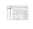
これにより、シフトレバー10をシフト操作したときにおける各シフト位置(R、N、H、D、L)における各センサ(ON・OFFセンサS1〜S4、リニアセンサR1,R2)からのセンサ出力は、図6に示すようになる。なお、図6のセンサ出力において、前記したように、1はON信号、0はOFF信号、Hは出力電圧が高い(高出力電圧)ときの信号、Mは出力電圧が中ぐらい(中出力電圧)のときの信号、Lは出力電圧が低い(低出力電圧)ときの信号を示している。
Thereby, the sensor output from each sensor (ON / OFF sensor S1-S4, linear sensor R1, R2) in each shift position (R, N, H, D, L) when the
よって、例えば、シフトレバー10のシフト位置がN位置の場合は、各センサ(ON・OFFセンサS1〜S4、リニアセンサR1,R2)から各センサ信号(“1、0、0、0、0、M、L”)を制御装置2に出力する。制御装置2は、入力されるこれらのセンサ信号に基づいてシフト位置がN位置と認識することができる。
Therefore, for example, when the shift position of the
このように、本実施形態では、図6に示したセンサ出力結果から明らかなように、シフトレバー10の各シフト位置(R、N、H、D、L)において、各センサ(ON・OFFセンサS1〜S4、リニアセンサR1,R2)から出力されるセンサ信号に基づいてシフト位置を検知することができる。
Thus, in this embodiment, as is apparent from the sensor output result shown in FIG. 6, at each shift position (R, N, H, D, L) of the
また、いずれかのセンサが故障したり信号線に断線等が発生した場合でも冗長性を確保しつつシフト位置検知を行うために、従来のように各シフト位置(R、N、H、D、Lの各位置)にそれぞれ2つ以上のセンサを配置すると、この場合、最低でも10個のセンサが必要となるが、本実施形態のシフト位置検知装置13を用いることにより、例えば、6つのセンサ(ON・OFFセンサS1〜S4、リニアセンサR1,R2)で、冗長性を確保しつつ各シフト位置(R、N、H、D、L)を確実に検知することが可能となり、かつ従来の場合よりもセンサの数を減らせるのでコストの低減を図ることができる。
Further, in order to detect the shift position while ensuring redundancy even when any one of the sensors breaks down or the signal line is disconnected, each shift position (R, N, H, D, If two or more sensors are arranged at each position of L), at least ten sensors are required in this case. By using the shift
なお、前記した実施形態におけるシフトレバー10のシフト位置(R、N、H、D、L)、ON・OFFセンサS1〜S4およびリニアセンサR1,R2の配置パターン、多極マグネット板15(マグネット15a〜15d)のN極、S極の配置パターンは一例であり、これに限定されるものではない。
In the above-described embodiment, the shift position (R, N, H, D, L) of the
また、前記した実施形態におけるON・OFFセンサS1〜S4は、多極マグネット板15のN極領域が対向位置にあって、N極の磁束密度が所定値よりも高い場合にON(=1)信号を出力する構成のセンサであったが、このON・OFFセンサS1〜S4を、多極マグネット板15のN極における検出特性とS極における検出特性に基づいて、多極マグネット板15の移動に伴ってS極からN極に移り変わった場合にON(=1)信号を出力する構成のセンサとすることもできる。
Further, the ON / OFF sensors S1 to S4 in the above-described embodiment are ON when the N-pole region of the
1 AT(自動変速機)
2 制御装置
3 シフト装置
5 エンジン
10 シフトレバー
11 P操作ボタン
13 シフト位置検知装置(シフト位置検知手段)
15 多極マグネット板
15a〜15d マグネット
S1〜S4 ON・OFFセンサ(第1の磁気センサ)
R1,R2 リニアセンサ(第2の磁気センサ)
1 AT (automatic transmission)
2
15
R1, R2 linear sensor (second magnetic sensor)
Claims (2)
前記シフト位置検知手段は、前記シフトレバーの下端部にこのシフトレバーのシフト操
作に応じて移動自在に設置されたマグネット板と、
前記マグネット板の前記シフトレバーと反対側に、前記各シフト位置に基づいて所定位置に非接触で複数配置され、前記マグネット板に対して磁束密度を検出し、検出した磁束密度の強弱に応じてON/OFF信号を出力する第1の磁気センサと、
前記マグネット板の前記シフトレバーと反対側に、前記各シフト位置に基づいて所定位置に非接触で少なくとも1個配置され、前記マグネット板に対して磁束密度を検出し、検出した磁束密度の大きさに応じた出力値を出力する第2の磁気センサと、を備えている、
ことを特徴とする自動変速機のシフト装置。 In a shift device for an automatic transmission, including a shift lever swingably supported at a plurality of shift positions along a shift groove, and shift position detecting means for detecting a shift position when the shift lever is operated,
The shift position detecting means includes a magnet plate installed at a lower end portion of the shift lever so as to be movable in accordance with a shift operation of the shift lever;
On the opposite side of the shift lever of the magnet plate, a plurality of non-contact arrangements are made at predetermined positions based on the shift positions, the magnetic flux density is detected with respect to the magnet plate, and depending on the strength of the detected magnetic flux density A first magnetic sensor that outputs an ON / OFF signal;
On the opposite side of the shift lever of the magnet plate, at least one non-contact is disposed at a predetermined position based on the shift positions, the magnetic flux density is detected with respect to the magnet plate, and the magnitude of the detected magnetic flux density. A second magnetic sensor that outputs an output value according to
A shift device for an automatic transmission.
前記第1の磁気センサを、前記N極における検出特性と前記S極における検出特性との変化を検出した場合にON信号もしくはOFF信号を出力するセンサとし、
前記第2の磁気センサを、前記多極マグネット板のN極もしくはS極に対して磁束密度を検出し、検出した磁束密度の大きさに応じた出力値を出力するセンサとした、
ことを特徴とする請求項1に記載の自動変速機のシフト装置。 The magnet plate is a multi-pole magnet plate formed by arranging a plurality of flat magnets so that the N pole and the S pole are adjacent to each other,
The first magnetic sensor is a sensor that outputs an ON signal or an OFF signal when a change between the detection characteristic at the N pole and the detection characteristic at the S pole is detected,
The second magnetic sensor is a sensor that detects a magnetic flux density with respect to the N-pole or S-pole of the multipole magnet plate and outputs an output value corresponding to the magnitude of the detected magnetic flux density.
The shift apparatus for an automatic transmission according to claim 1.
Priority Applications (2)
| Application Number | Priority Date | Filing Date | Title |
|---|---|---|---|
| JP2005174844A JP4344343B2 (en) | 2005-06-15 | 2005-06-15 | Automatic transmission shift device |
| US11/424,143 US7552659B2 (en) | 2005-06-15 | 2006-06-14 | Gearshift device for automatic transmission |
Applications Claiming Priority (1)
| Application Number | Priority Date | Filing Date | Title |
|---|---|---|---|
| JP2005174844A JP4344343B2 (en) | 2005-06-15 | 2005-06-15 | Automatic transmission shift device |
Publications (2)
| Publication Number | Publication Date |
|---|---|
| JP2006347314A true JP2006347314A (en) | 2006-12-28 |
| JP4344343B2 JP4344343B2 (en) | 2009-10-14 |
Family
ID=37572046
Family Applications (1)
| Application Number | Title | Priority Date | Filing Date |
|---|---|---|---|
| JP2005174844A Expired - Fee Related JP4344343B2 (en) | 2005-06-15 | 2005-06-15 | Automatic transmission shift device |
Country Status (2)
| Country | Link |
|---|---|
| US (1) | US7552659B2 (en) |
| JP (1) | JP4344343B2 (en) |
Cited By (9)
| Publication number | Priority date | Publication date | Assignee | Title |
|---|---|---|---|---|
| EP2000705A2 (en) | 2007-06-07 | 2008-12-10 | Honda Motor Co., Ltd | Shift apparatus |
| JP2009120062A (en) * | 2007-11-15 | 2009-06-04 | Suzuki Motor Corp | Shifting device for automatic transmission |
| JP2010107376A (en) * | 2008-10-30 | 2010-05-13 | Honda Motor Co Ltd | Position detection device |
| JP2012046046A (en) * | 2010-08-26 | 2012-03-08 | Fuji Kiko Co Ltd | Shift lever device |
| US9163957B2 (en) | 2011-09-12 | 2015-10-20 | Kabushiki Kaisha Tokai Rika Denki Seisakusho | Position sensor |
| CN107356273A (en) * | 2016-05-09 | 2017-11-17 | 成都安驭科技有限公司 | A kind of method for improving code detection device reliability |
| JP2017217997A (en) * | 2016-06-07 | 2017-12-14 | 株式会社ユーシン | Shift position detector |
| JP2021128044A (en) * | 2020-02-13 | 2021-09-02 | 株式会社デンソー | Position sensor |
| WO2024024485A1 (en) * | 2022-07-26 | 2024-02-01 | パナソニックIpマネジメント株式会社 | Input device |
Families Citing this family (27)
| Publication number | Priority date | Publication date | Assignee | Title |
|---|---|---|---|---|
| DE102004024954A1 (en) * | 2004-05-21 | 2005-12-08 | Robert Bosch Gmbh | Sensor for a transmission control in particular of a motor vehicle |
| DE102004060771B4 (en) * | 2004-12-17 | 2006-12-21 | Audi Ag | Device for switching translation changes |
| KR100800126B1 (en) * | 2006-08-17 | 2008-01-31 | 에스엘 주식회사 | Electronic shift lever |
| US7983822B2 (en) * | 2006-09-05 | 2011-07-19 | GM Global Technology Operations LLC | Dual wire internal mode switch assembly |
| FR2925139B1 (en) * | 2007-12-17 | 2010-01-08 | Sc2N Sa | POSITION SENSOR OF A GEARBOX AND CORRESPONDING GEAR BOX |
| GB2466185B (en) * | 2008-12-09 | 2013-01-02 | Ford Global Tech Llc | A method and apparatus for establishing the engagement state of a manual transmission |
| DE102009053873A1 (en) * | 2009-11-20 | 2011-06-09 | Ecs Engineered Control Systems Ag | Device for detecting the position of a shift and / or selector lever for a transmission and switching device for the transmission of a motor vehicle |
| GB2475846B (en) * | 2009-12-01 | 2016-12-14 | Gm Global Tech Operations Llc | Manual gear shift mechanism |
| DE112011100277T5 (en) * | 2010-01-19 | 2012-11-08 | Honda Motor Co., Ltd. | switching device |
| KR101349471B1 (en) * | 2010-12-09 | 2014-01-10 | 에스엘 주식회사 | Shifting Apparatus for Vehicle |
| WO2013043772A1 (en) * | 2011-09-22 | 2013-03-28 | Tyco Electronics Corporation | Switch assembly and system |
| US8816804B2 (en) | 2011-09-22 | 2014-08-26 | Tyco Electronics Corporation | Switch assembly and system |
| KR101393902B1 (en) * | 2011-12-13 | 2014-05-12 | 현대자동차주식회사 | Shift lever improving operability in automatic transmission |
| FR2988339B1 (en) * | 2012-03-21 | 2014-04-04 | Dura Automotive Systems Sas | DEVICE FOR DETECTING THE P, R, N, D, M +, M AND M POSITIONS OF A LEVER FOR CONTROLLING A GEARBOX OF A MOTOR VEHICLE |
| FR2993029B1 (en) | 2012-07-03 | 2014-08-08 | Dura Automotive Systems Sas | DEVICE FOR CAPTURING THE LINEAR POSITION OF A TRANSMISSION DEVICE IN THE FORM OF A CABLE SUBJECTED TO A LEVER OF A GEAR CONTROL BOX OF A MOTOR VEHICLE |
| JP6006027B2 (en) * | 2012-07-18 | 2016-10-12 | 株式会社東海理化電機製作所 | Position sensor |
| KR101384532B1 (en) * | 2013-05-03 | 2014-04-11 | 현대자동차주식회사 | Electronic shift lever |
| KR101421957B1 (en) * | 2013-08-06 | 2014-07-22 | 현대자동차주식회사 | Organ-type electronic shift lever |
| WO2015033320A2 (en) | 2013-09-06 | 2015-03-12 | Kongsberg Automotive Ab | Shifter assembly having a sensing arrangement |
| KR101511561B1 (en) * | 2013-12-18 | 2015-04-13 | 현대자동차주식회사 | Smart Touch Type Electronic Auto Shift Lever |
| DE102014223046A1 (en) * | 2014-11-12 | 2016-05-12 | Zf Friedrichshafen Ag | Coupling device for a shift lever, shift lever device and method for producing a coupling device |
| US9879775B2 (en) * | 2015-11-13 | 2018-01-30 | Sl Corporation | Shifting lever assembly |
| CN108953595A (en) * | 2017-05-18 | 2018-12-07 | 泰科电子(上海)有限公司 | For sensing the sensor-based system of gear rotating shaft position |
| CN108953596A (en) * | 2017-05-18 | 2018-12-07 | 泰科电子(上海)有限公司 | For sensing the sensor-based system of gear rotating shaft position |
| JP7409601B2 (en) * | 2018-01-05 | 2024-01-09 | 株式会社東海理化電機製作所 | shift device |
| MY202628A (en) * | 2018-01-16 | 2024-05-10 | Tsuda Ind Co Ltd | Shift device |
| JP7281690B2 (en) * | 2018-09-20 | 2023-05-26 | パナソニックIpマネジメント株式会社 | Position detector |
Family Cites Families (10)
| Publication number | Priority date | Publication date | Assignee | Title |
|---|---|---|---|---|
| TW248544B (en) * | 1991-04-03 | 1995-06-01 | Torrington Co | |
| FR2692956A1 (en) * | 1992-06-29 | 1993-12-31 | Peugeot | Alarm device to detect position or change of position of manoeuvring lever such as gear lever - uses detectors under bottom end of lever to detect magnetic field generated by magnet carried by lever when gear selections are made |
| US6064197A (en) * | 1997-07-26 | 2000-05-16 | U.S. Philips Corporation | Angle sensor having lateral magnetic field sensor element and axial magnetic field direction measuring element for determining angular position |
| DE19905627B4 (en) * | 1998-02-16 | 2008-09-25 | Luk Gs Verwaltungs Kg | Transmission for a motor vehicle with a selector |
| JP2000123686A (en) | 1998-10-19 | 2000-04-28 | Matsushita Electric Works Ltd | Shift position sensing device |
| DE19855358A1 (en) | 1998-12-01 | 2000-06-08 | Bosch Gmbh Robert | Path-measuring device, especially for brake pedal movement in vehicle has at least one analog sensor and at least one incremental sensor to output analog and pulse train signals of path, respectively |
| JP4481438B2 (en) | 2000-05-31 | 2010-06-16 | 株式会社東海理化電機製作所 | Shift device |
| DE10049307B4 (en) * | 2000-10-04 | 2013-01-31 | Volkswagen Ag | Sensor system for the control device of an automatically shiftable transmission |
| DE10102843C2 (en) * | 2001-01-22 | 2003-07-17 | Zf Lemfoerder Metallwaren Ag | Switching device for switching between different operating states of a motor vehicle transmission |
| KR100726546B1 (en) * | 2005-10-05 | 2007-06-11 | 현대모비스 주식회사 | Vehicle electronic shift lever structure |
-
2005
- 2005-06-15 JP JP2005174844A patent/JP4344343B2/en not_active Expired - Fee Related
-
2006
- 2006-06-14 US US11/424,143 patent/US7552659B2/en not_active Expired - Fee Related
Cited By (14)
| Publication number | Priority date | Publication date | Assignee | Title |
|---|---|---|---|---|
| EP2000705A2 (en) | 2007-06-07 | 2008-12-10 | Honda Motor Co., Ltd | Shift apparatus |
| JP2008302792A (en) * | 2007-06-07 | 2008-12-18 | Honda Motor Co Ltd | Shift device |
| US7966905B2 (en) | 2007-06-07 | 2011-06-28 | Honda Motor Co., Ltd. | Shift apparatus |
| JP2009120062A (en) * | 2007-11-15 | 2009-06-04 | Suzuki Motor Corp | Shifting device for automatic transmission |
| JP2010107376A (en) * | 2008-10-30 | 2010-05-13 | Honda Motor Co Ltd | Position detection device |
| JP2012046046A (en) * | 2010-08-26 | 2012-03-08 | Fuji Kiko Co Ltd | Shift lever device |
| US9163957B2 (en) | 2011-09-12 | 2015-10-20 | Kabushiki Kaisha Tokai Rika Denki Seisakusho | Position sensor |
| CN107356273A (en) * | 2016-05-09 | 2017-11-17 | 成都安驭科技有限公司 | A kind of method for improving code detection device reliability |
| CN107356273B (en) * | 2016-05-09 | 2021-04-30 | 成都安驭科技有限公司 | Method for improving reliability of code detection device |
| JP2017217997A (en) * | 2016-06-07 | 2017-12-14 | 株式会社ユーシン | Shift position detector |
| JP2021128044A (en) * | 2020-02-13 | 2021-09-02 | 株式会社デンソー | Position sensor |
| JP7279660B2 (en) | 2020-02-13 | 2023-05-23 | 株式会社デンソー | position sensor |
| JP7559865B2 (en) | 2020-02-13 | 2024-10-02 | 株式会社デンソー | Position Sensors |
| WO2024024485A1 (en) * | 2022-07-26 | 2024-02-01 | パナソニックIpマネジメント株式会社 | Input device |
Also Published As
| Publication number | Publication date |
|---|---|
| US20060283276A1 (en) | 2006-12-21 |
| US7552659B2 (en) | 2009-06-30 |
| JP4344343B2 (en) | 2009-10-14 |
Similar Documents
| Publication | Publication Date | Title |
|---|---|---|
| JP4344343B2 (en) | Automatic transmission shift device | |
| US7421923B2 (en) | Electronic gearshift structure for vehicle | |
| CN106560636B (en) | Electronic gear shift system | |
| JP4806647B2 (en) | Lever operating position determination device for transmission operating lever | |
| JP4068393B2 (en) | Shift device | |
| JP5607594B2 (en) | Position sensor | |
| WO2011090011A1 (en) | Shift device | |
| JP4886606B2 (en) | Lever device | |
| JP4500327B2 (en) | Shift device | |
| KR101312178B1 (en) | Column Type Transmission Lever Assembly | |
| JP2004138235A (en) | Shift lever device | |
| JP5033105B2 (en) | Position detection device | |
| JP2016109292A (en) | Shift lever position determination device for vehicle | |
| JP2011080839A (en) | Position detecting device and shift device | |
| CN101915300B (en) | Noncontact magnetically inductive AMT shifting handle actuating mechanism | |
| JP6853900B2 (en) | Shift device | |
| JP2000179681A (en) | Gear stage detection device for vehicle transmission | |
| JP2008032155A (en) | Shift lever position detector | |
| JP4616708B2 (en) | Position detection device | |
| CN205896141U (en) | Gearshift, shift system and vehicle | |
| KR101315583B1 (en) | Shift Lever Position Sensing Device for Transmission of Vehicle | |
| JP2007278720A (en) | Position detector and shift device | |
| JP5427112B2 (en) | Position sensor | |
| JP2017009106A (en) | Electronic transmission system for vehicles using smart keys | |
| JP5637066B2 (en) | Inhibitor switch |
Legal Events
| Date | Code | Title | Description |
|---|---|---|---|
| A977 | Report on retrieval |
Free format text: JAPANESE INTERMEDIATE CODE: A971007 Effective date: 20090122 |
|
| A131 | Notification of reasons for refusal |
Free format text: JAPANESE INTERMEDIATE CODE: A131 Effective date: 20090127 |
|
| RD13 | Notification of appointment of power of sub attorney |
Free format text: JAPANESE INTERMEDIATE CODE: A7433 Effective date: 20090324 |
|
| A521 | Written amendment |
Free format text: JAPANESE INTERMEDIATE CODE: A523 Effective date: 20090327 |
|
| A521 | Written amendment |
Free format text: JAPANESE INTERMEDIATE CODE: A821 Effective date: 20090327 |
|
| TRDD | Decision of grant or rejection written | ||
| A01 | Written decision to grant a patent or to grant a registration (utility model) |
Free format text: JAPANESE INTERMEDIATE CODE: A01 Effective date: 20090707 |
|
| A01 | Written decision to grant a patent or to grant a registration (utility model) |
Free format text: JAPANESE INTERMEDIATE CODE: A01 |
|
| A61 | First payment of annual fees (during grant procedure) |
Free format text: JAPANESE INTERMEDIATE CODE: A61 Effective date: 20090710 |
|
| FPAY | Renewal fee payment (event date is renewal date of database) |
Free format text: PAYMENT UNTIL: 20120717 Year of fee payment: 3 |
|
| R150 | Certificate of patent or registration of utility model |
Free format text: JAPANESE INTERMEDIATE CODE: R150 |
|
| FPAY | Renewal fee payment (event date is renewal date of database) |
Free format text: PAYMENT UNTIL: 20120717 Year of fee payment: 3 |
|
| FPAY | Renewal fee payment (event date is renewal date of database) |
Free format text: PAYMENT UNTIL: 20130717 Year of fee payment: 4 |
|
| FPAY | Renewal fee payment (event date is renewal date of database) |
Free format text: PAYMENT UNTIL: 20140717 Year of fee payment: 5 |
|
| LAPS | Cancellation because of no payment of annual fees |