JP2006347317A - Brake drum pallet - Google Patents
Brake drum pallet Download PDFInfo
- Publication number
- JP2006347317A JP2006347317A JP2005174868A JP2005174868A JP2006347317A JP 2006347317 A JP2006347317 A JP 2006347317A JP 2005174868 A JP2005174868 A JP 2005174868A JP 2005174868 A JP2005174868 A JP 2005174868A JP 2006347317 A JP2006347317 A JP 2006347317A
- Authority
- JP
- Japan
- Prior art keywords
- brake drum
- pallet
- brake
- frames
- dolly
- Prior art date
- Legal status (The legal status is an assumption and is not a legal conclusion. Google has not performed a legal analysis and makes no representation as to the accuracy of the status listed.)
- Pending
Links
Images






Classifications
-
- B—PERFORMING OPERATIONS; TRANSPORTING
- B60—VEHICLES IN GENERAL
- B60B—VEHICLE WHEELS; CASTORS; AXLES FOR WHEELS OR CASTORS; INCREASING WHEEL ADHESION
- B60B29/00—Apparatus or tools for mounting or dismounting wheels
Landscapes
- Handcart (AREA)
Abstract
【課題】普及しているホイールドーリにアタッチメントを用いることで、ブレーキドラムのみを取外し可能とし、新たなブレーキドラムドーリの機械を必要とせず、普及しているホイールドーリとアタッチメントのみで、タイヤとブレーキドラムを別々に脱着、点検を可能となるアタッチメントを提供する。
【解決手段】前後に設けたフレーム2、3と、該フレーム2、3間に架設した一対の側枠4、5と、側枠4、5間に配設したブレーキドラム取付部8とを設けたブレーキドラムパレット。
【選択図】図1
[PROBLEMS] To remove only a brake drum by using an attachment for a popular wheel dolly, without requiring a new brake drum dolly machine, and to use only a popular wheel dolly and attachment for a tire and a brake. To provide an attachment that allows the drum to be detached and inspected separately.
SOLUTION: Frames 2 and 3 provided at the front and rear, a pair of side frames 4 and 5 provided between the frames 2 and 3, and a brake drum mounting portion 8 provided between the side frames 4 and 5 are provided. Brake drum pallet.
[Selection] Figure 1
Description
本発明はブレーキドラムパレットに関するもので、より詳しくは、他の昇降手段(例えば、ホイールドーリ)を用いて使用し、大型トラック、バス等のブレーキドラムの交換と運搬をする場合に使用するブレーキドラムパレットに関する。 The present invention relates to a brake drum pallet. More specifically, the present invention relates to a brake drum which is used when other lifting means (for example, a wheel dolly) is used to exchange and transport a brake drum such as a large truck or bus. Regarding the pallet.
従来、大型トラック、バス等のブレーキドラムの点検においては、タイヤとブレーキドラムを一体として、例えば特許文献1記載のホイールドーリを用いて車体から取り外して行い、タイヤとブレーキドラムとを別々に車体から取外すことは少なかった。
Conventionally, when inspecting brake drums for large trucks, buses, etc., the tire and brake drum are integrated and removed from the vehicle body using, for example, a wheel dolly described in
しかし、近年、車体からタイヤとブレーキドラムを別々に外し、タイヤとブレーキドラム間の点検が行なわれるようになってきた。前記ホイールドーリにおいては、タイヤのみを車体から取外すことはできるが、車体からブレーキドラムのみを取外すことができるようには設計されていないため、ブレーキドラムのみを車体から取外す専用の機械としてブレーキドラムドーリが提案されている。
車体からタイヤとブレーキドラムとを別々に取外すためには、車体からタイヤを取外すホイールドーリと、ブレーキドラムを取外すブレーキドラムドーリの2種類の機械が必要となる。また、ブレーキドラムドーリは1つのブレーキドラムに対して1台必要である。 In order to separately remove the tire and the brake drum from the vehicle body, two types of machines are required: a wheel dolly for removing the tire from the vehicle body, and a brake drum dolly for removing the brake drum. One brake drum dolly is required for one brake drum.
大型トラック、バス等の大型車を点検する場合には、ブレーキドラムを8本から10本を全て外してから行なうことがあり、ブレーキドラムドーリが8台から10台必要となり設備投資費用が多大になるという問題点がある。 When inspecting large vehicles such as large trucks and buses, there are cases where 8 to 10 brake drums are removed, and 8 to 10 brake drum dollies are required, resulting in large capital investment costs. There is a problem of becoming.
一方、ホイールドーリは広く普及している。
そこで、本発明は、この普及しているホイールドーリにアタッチメントを用いることで、ブレーキドラムのみを取外し可能とし、新たなブレーキドラムドーリの機械を必要とせず、普及しているホイールドーリとアタッチメントのみで、タイヤとブレーキドラムを別々に脱着、点検を可能となるアタッチメントを提供することを目的とするものである。
On the other hand, wheel dolls are widely used.
Therefore, the present invention makes it possible to remove only the brake drum by using an attachment for this popular wheel dolly, and does not require a new brake drum dolly machine, only the popular wheel dolly and attachment. An object of the present invention is to provide an attachment that enables the tire and the brake drum to be detached and inspected separately.
前記の課題を解決するために、請求項1記載の発明は、前後に設けたフレームと、該フレーム間に架設した一対の側枠と、側枠間に配設したブレーキドラム取付部とを設けたことを特徴とするものである。
In order to solve the above-mentioned problem, the invention according to
請求項2記載の発明は、請求項1記載の発明において、前記ブレーキドラム取付部は、起立したドラム取付板と、2個の長穴とからなることを特徴とするものである。 According to a second aspect of the present invention, in the first aspect of the invention, the brake drum mounting portion includes a standing drum mounting plate and two elongated holes.
請求項3記載の発明は、前記請求項1又は2記載のブレーキドラムパレット全体を昇降させる他の昇降手段に係止する係止手段を設けたことを特徴とするものである。 According to a third aspect of the present invention, there is provided a locking means for locking to another lifting means for lifting and lowering the entire brake drum pallet according to the first or second aspect.
請求項4記載の発明は、請求項1乃至3記載の発明において、前記フレーム又は前記側枠の下部に積み重ね手段を設けたことを特徴とするものである。 According to a fourth aspect of the present invention, in the first to third aspects of the present invention, stacking means is provided at a lower portion of the frame or the side frame.
本発明によれば、例えば昇降手段として普及しているホイールドーリのアタッチメントとして本発明のブレーキドラムパレットを用いることで、ブレーキドラムのみを取外し可能となり、新たなブレーキドラムドーリの機械を必要とせず、普及しているホイールドーリと本発明のブレーキドラムパレットで、タイヤとブレーキドラムを別々に脱着、点検が行なえ、設備投資費用を少なく抑えることができる。 According to the present invention, for example, by using the brake drum pallet of the present invention as an attachment of a wheel dolly popular as an elevating means, it becomes possible to remove only the brake drum, without requiring a new brake drum dolly machine, With the popular wheel dolly and the brake drum pallet of the present invention, the tire and the brake drum can be detached and inspected separately, and the capital investment cost can be reduced.
請求項2記載の発明によれば、更に、種類の異なるブレーキドラムに対応が出来る。例えば、ブレーキドラムのタイヤホイール取付ねじが、6本、8本、10本と異なる種類のブレーキドラムに対応することが出来る。
According to the invention described in
請求項3記載の発明によれば、更に、昇降手段に対するブレーキドラムパレットの移動が阻止され安全に作業を行なうことができる。 According to the third aspect of the present invention, the brake drum pallet is prevented from moving relative to the elevating means, and the work can be performed safely.
請求項4記載の発明によれば、更に、ブレーキドラムパレットを積み重ねることが出来るため、不使用時の収納性がよい。
According to invention of
本発明を実施するための最良の形態を図に基づいて説明する。
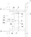
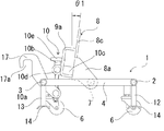
図1はブレーキドラムパレット1の側面図、図2はブレーキドラムパレット1の前面図、図3はブレーキドラムパレット1の後面図、図4はブレーキドラムパレット1の上面図である。
The best mode for carrying out the present invention will be described with reference to the drawings.
1 is a side view of the
ブレーキドラムパレット1は、パイプ状に形成された前フレーム2と後フレーム3を有し、該前後フレーム2、3間には一対の側枠4、5が設けられている。該側枠4、5の前後下部にはキャスター6が回転可能に設けられている。
The
該側枠4、5間には、取付フレーム7が固定して配設され、該取付フレーム7にはブレーキドラム取付部8の側板部8a、8bが回転可能に設けられている。ブレーキドラム取付部8は、側板部8a、8bと、ドラム取付板8cと、グリップ9a、9bで構成されている。ドラム取付板8cは、側枠4、5より起立し、側板部8a、8bの後部で、側板部8a、8b間に亘って設けられ、図4に示すように、側板部8a、8bとドラム取付板8cは上部から見てコ字状に形成されている。グリップ9a、9bは、ドラム取付板8cから後方に、側部から見てコ字状に突出して設けられている。
A
前記後フレーム3には腕板10aが固設されており、該腕板10aの下部には、角度調整ねじ10bの下部が前後方向に回転可能に設けられている。該角度調整ねじ(雄ねじ)10bには、前記ドラム取付板8cに突設した腕板10cに設けた雌ねじ部10dが螺合しており、角度調整ねじ10bを操作部10eにより正逆回転することにより腕板10cを昇降して、ブレーキドラム取付部8を取付フレーム7を中心として前後方向に回動するようになっている。本実施例においては、ブレーキドラム取付部8は、図5、6に示すように、鉛直方向に対して前方にθ1=7.5°から後方にθ2=7.5°の範囲内で回動するように設定されている。腕板10aと角度調整ねじ10bと腕板10cと雌ねじ部10dと操作部10eより角度調整手段10が構成されている。なお、θ1、θ2は7.5°に限らず、所望に設定するものである。
An
ブレーキドラム取付部8のドラム取付板8cには、図2に示すように、左右方向の中央部で、かつ、上半部に、上方が略V字状に開口する切欠部8dが設けられ、該切欠部8dを挟んで左右対称にドラム取付用の長穴11a、11bが2個設けられている。該ドラム取付用の長穴11a、11bは、外側ほど上方に傾斜するように形成され、内径はブレーキドラムに突設した取付ねじ(ボルト)が挿通する径に形成されている。長穴11a、11bの中心間の間隔は任意に設定するが、本実施例においては、該長穴11a、11bの下端部中心間の間隔L1は172mm、長穴11a、11bの上端部中心間の間隔L2は218mmに設定されている。このように、長穴11a、11bを形成することにより、径の異なるブレーキドラムの取付ねじ(ボルト)を挿通できるようになっている。
As shown in FIG. 2, the
前記前後フレーム2、3の左右の下端部には、前記キャスター6、6の外側に位置するようにして積み重ね手段である脚12、13が、下方へ突設されている。該脚12、13は、前後フレーム2、3から下方向に突出し、脚12、13の下端部には重ね積み用の載置板14、14が設けられ、該載置板14の前後部は下方向に湾曲している。また、脚12、13の下端つまり載置板14、14の下端は、キャスター6、6の下端部より上方に位置するように設定されている。
前記後フレーム3には、係止手段であるフック17が設けられている。該フック17は、後フレーム3から後方に突出しているとともに、下方が開口する係止部17aを形成している。該フック17は、後述するホイールドーリ21の回転軸45、46に、上方から係止できる位置に設けられている。
The
前記の構造により、ブレーキドラムパレット1は、図7、図8に示すように、他のブレーキドラムパレット1とは前後を逆向きにして、下段のブレーキドラムパレット1の前記前後フレーム2、3の上面に上段のブレーキドラムパレット1の重ね積み用の載置板14、14を載せることにより、複数のブレーキドラムパレット1を積み重ねることができ、ブレーキドラムパレット1の不使用時の収納性がよい。
Due to the above structure, the
次に、ブレーキドラムパレット1全体を昇降させる昇降手段であるホイールドーリ21について説明する。
Next, the
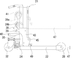
図9はホイールドーリ21の側面図で、図10はホイールドーリ21の前面図、図11はホイールドーリ21の後面図、図12はホイールドーリ1の上面図である。
9 is a side view of the
ホイールドーリ21は一対のフレーム22、23を有し、該フレーム22、23は同一平面内において略平行に配置され、該両フレーム22、23の後部上面には支柱24、25が固着されて立設されている。該両フレーム22、23間には連結材26が架設して固定されており、前記両フレーム22、23と連結材26は、図12に示すように、上方から見て前側が開口する略コ字状に配置されている。
The
前記両フレーム22、23の前端には前車輪28、29が付設され、前記連結材26の両側部の後部に固設した車輪取付材30、31には後車輪32、33が付設されている。
連結材26の上面には取付台34が固設されており、該取付台34上に後述する支承アーム47、48の駆動機構38が搭載されている。該駆動機構38は、油圧シリンダ39と操作部40とチェーン41より構成されている。
A mounting
操作部40を上下に移動させることにより、図示しないポンプ機構によって、油圧シリンダ39のロッド39aが昇降する。該ロッド39aの上端部にはチェーンホイール39bが回転可能に設けられている。チェーン41の一端は取付台34に固着され、他端は連結材26の前方に連結材26と略平行に設けられた連結枠42に固着され、チェーン41の中間は前記チェーンホイール39bに架設している。
By moving the
前記両支柱24、25には、昇降部材43、44が支柱24、25に沿って昇降可能に設けられている。該両昇降部材43、44間の前方には前記連結枠42が固設されている。該連結枠42の左右端部には、その前方に突出する腕板43a、44aによりは回転軸45、46が固設されており、該回転軸45、46は左右方向に水平に配置されている。該回転軸45、46には支承アーム47、48が回動可能に連結されている。該一対の支承アーム47、48は同一平面内において相互に平行に配置され、回転軸45、46に対して略直角に配設されている。また、各支承アーム47、48の左右幅は、各回転軸45、46の左右幅よりも短く設定されており、支承アーム47、48が左右方向に平行に移動することが出来るようになっている。支承アーム47、48の地面に対する角度は、角度調節ネジ49、50により調節することができるようになっており、角度調節ネジ49、50を締め付けることにより、支承アーム47、48が回転軸45、46を中心として前側が上昇するようになっている。該支承アーム47、48の前後方向の長さは、前記ブレーキドラムパレット1の前後フレーム2、3間の間隔よりも長く設定されている。
Elevating
したがって、前記昇降部材43、44と、連結枠42と、支承アーム47、48は一体的に、支柱24、25に沿って昇降するようになっている。
Therefore, the elevating
連結枠42に連結された前記チェーン41を前記油圧シリンダ39によって昇降することにより、支承アーム47、48を一体的に昇降し、連結枠42を水平状態で昇降するようになっている。
The
次に、ブレーキドラムパレット1の使用方法について説明する。
先ず、整備工場などにおいて、大型車、中型車のトラック等をリフトにより所定の高さまで持ち上げ、ホイールドーリ21を使用し、その支承アーム47、48を上昇し、この支承アーム47、48にタイヤ及びタイヤホイールを支承して取外す。
Next, a method for using the
First, at a maintenance shop or the like, a truck of a large vehicle or a medium-sized vehicle is lifted up to a predetermined height by using a lift, and the
次に、ホイールドーリ21の支承アーム47、48を最下端にまで降下させて、タイヤ及びタイヤホイールを支承アーム47、48より取りおろす。
Next, the
次に、支承アーム47、48がブレーキドラムパレット1の脚12、13の外側で前後フレーム2、3の下部に位置するように支承アーム47、48の左右方向の位置を調節する。
Next, the positions of the
次に、ブレーキドラムパレット1を、その後部が、図13、図14に示すように、ホイールドーリ21の回転軸45、46の前部に当接するまで移動させる。
Next, the
この状態から、操作部40を上下に移動させて、油圧シリンダ39のロッド39aを上昇させることにより、チェーンホイール39bが上昇し、チェーンホイール39bによりチェーン41が押し上げられる。これにより、チェーン41の他端に連結された連結枠42が上昇し、該連結枠42に連結された支承アーム47、48が上昇する。該支承アーム47、48の上昇により、ブレーキドラムパレット1の前後フレーム2、3は下部より押し上げられ、ブレーキドラムパレット1全体が持ち上げられる。
From this state, the operating
支承アーム47、48が前後フレーム2、3に当接するときに、図16に示すように、ブレーキドラムパレット1の係止手段であるフック17が、ホイールドーリ21の回転軸45、46に上方から係止し、ブレーキドラムパレット1がホイールドーリ21に対して前後に移動することを阻止する。
When the
そして、ブレーキドラムパレット1を、前記の車両におけるブレーキドラム52の位置まで上昇させ(図16参照)、ブレーキドラム取付部8を角度調整手段10によりブレーキドラム面と平行となるように調節する。
Then, the
そして、ブレーキドラム52のタイヤホイール取付ねじ53(図13参照)の1個を最下端に位置するように回転させ、該最下端の取付ねじ53を切欠部8dに、該最下端の取付ねじ53の両側に位置する2つの取付ねじ53をブレーキドラム取付部8のドラム取付用の長穴11a、11bに対応するように位置を調節する。そして、ホイールドーリ21を前進させて、長穴11a、11bに前記取付ねじ53を貫通させ、該取付ねじ53にナット54を螺合させることにより、ブレーキドラム取付部8にブレーキドラム52が固定される。
Then, one of the tire wheel mounting screws 53 (see FIG. 13) of the
次に、ホイールドーリ21を後退することにより車体よりブレーキドラム52を取外し、ホイールドーリ21の支承アーム47、48を下降して、図13に示すように、ブレーキドラム52を固定したブレーキドラムパレット1を、そのキャスター6が地表に接するまで降下させる。そして、このブレーキドラム52を固定したブレーキドラムパレット1を、そのキャスター6により移動して、ホイールドーリ21より分離し、適宜位置の地上に置く。
Next, the
次に、他のブレーキドラムパレット1をホイールドーリ21により、前記と同様に上昇させて他のブレーキドラムを取外す。これを繰り返すことにより、1台のホイールドーリ21と自動車のタイヤの数と同数のブレーキドラムパレット1を使用して、1台の自動車のタイヤ等とブレーキドラム52を別々に取外すことができる。
Next, the other
また、ドラム取付用の長穴11a、11bを外側ほど上方に傾斜させ、その下端部中心間の間隔L1を172mm、上端部中心間の間隔L2を218mmに設定したことで、ブレーキドラムの最下端の取付ねじ53の両側に位置する2本の取付ねじ53間のピッチの間隔が218mm〜172mmの範囲にある複数のブレーキドラム52に対応できる。つまり、タイヤホイールのブレーキドラムに対するボルト締めの数が、6本、8本、10本と複数の種類のブレーキドラムに対応することが出来る。
Further, the
リフトアップされた車体にブレーキドラム52を装着する場合は、前記と逆の操作により行う。
When the
なお、前記実施例では、ブレーキドラムパレット1を昇降させる昇降手段として、ホイールドーリ21を用いたが、このホイールドーリ以外にフォークリフト等の昇降手段を用いて、このフォークリフト等で前記のブレーキドラムパレット1を昇降してもよい。
In the above embodiment, the
1 ブレーキドラムパレット
2、3 フレーム
4、5 側枠
8 ブレーキドラム取付部
8c ドラム取付板
11a、11b ブレーキドラム取付用の長穴
12、13 積み重ね手段(脚)
17 係止手段(フック)
21 他の昇降手段(ホイールドーリ)
DESCRIPTION OF
17 Locking means (hook)
21 Other lifting means (wheel doli)
Claims (4)
4. The brake drum pallet according to claim 1, wherein a stacking means is provided at a lower portion of the frame or the side frame.
Priority Applications (1)
| Application Number | Priority Date | Filing Date | Title |
|---|---|---|---|
| JP2005174868A JP2006347317A (en) | 2005-06-15 | 2005-06-15 | Brake drum pallet |
Applications Claiming Priority (1)
| Application Number | Priority Date | Filing Date | Title |
|---|---|---|---|
| JP2005174868A JP2006347317A (en) | 2005-06-15 | 2005-06-15 | Brake drum pallet |
Publications (1)
| Publication Number | Publication Date |
|---|---|
| JP2006347317A true JP2006347317A (en) | 2006-12-28 |
Family
ID=37643609
Family Applications (1)
| Application Number | Title | Priority Date | Filing Date |
|---|---|---|---|
| JP2005174868A Pending JP2006347317A (en) | 2005-06-15 | 2005-06-15 | Brake drum pallet |
Country Status (1)
| Country | Link |
|---|---|
| JP (1) | JP2006347317A (en) |
Cited By (1)
| Publication number | Priority date | Publication date | Assignee | Title |
|---|---|---|---|---|
| CN108248656A (en) * | 2018-01-06 | 2018-07-06 | 南昌诺义弘科技有限公司 | A kind of processing and manufacturing of lithium battery is with classifying equipment |
Citations (6)
| Publication number | Priority date | Publication date | Assignee | Title |
|---|---|---|---|---|
| JPH1042617A (en) * | 1996-08-05 | 1998-02-17 | Denken Eng Kk | Self-propelled vehicle for agricultural and horticultural use |
| JPH10129206A (en) * | 1996-10-30 | 1998-05-19 | Anzen Motor Car Co Ltd | Wheel dolly for maintenance of vehicle, and tire carry |
| JPH10129494A (en) * | 1996-10-30 | 1998-05-19 | Hino Motors Ltd | Car wheel carrier and holding device |
| JP2000289742A (en) * | 1999-04-02 | 2000-10-17 | Daifuku Co Ltd | Article storage tool and method for its use |
| JP2002067967A (en) * | 2000-08-31 | 2002-03-08 | Toshiba Plant Kensetsu Co Ltd | Pallet truck |
| JP2005088965A (en) * | 2003-09-19 | 2005-04-07 | Daifuku Co Ltd | Stackable conveying carriage |
-
2005
- 2005-06-15 JP JP2005174868A patent/JP2006347317A/en active Pending
Patent Citations (6)
| Publication number | Priority date | Publication date | Assignee | Title |
|---|---|---|---|---|
| JPH1042617A (en) * | 1996-08-05 | 1998-02-17 | Denken Eng Kk | Self-propelled vehicle for agricultural and horticultural use |
| JPH10129206A (en) * | 1996-10-30 | 1998-05-19 | Anzen Motor Car Co Ltd | Wheel dolly for maintenance of vehicle, and tire carry |
| JPH10129494A (en) * | 1996-10-30 | 1998-05-19 | Hino Motors Ltd | Car wheel carrier and holding device |
| JP2000289742A (en) * | 1999-04-02 | 2000-10-17 | Daifuku Co Ltd | Article storage tool and method for its use |
| JP2002067967A (en) * | 2000-08-31 | 2002-03-08 | Toshiba Plant Kensetsu Co Ltd | Pallet truck |
| JP2005088965A (en) * | 2003-09-19 | 2005-04-07 | Daifuku Co Ltd | Stackable conveying carriage |
Cited By (1)
| Publication number | Priority date | Publication date | Assignee | Title |
|---|---|---|---|---|
| CN108248656A (en) * | 2018-01-06 | 2018-07-06 | 南昌诺义弘科技有限公司 | A kind of processing and manufacturing of lithium battery is with classifying equipment |
Similar Documents
| Publication | Publication Date | Title |
|---|---|---|
| JP2004243805A (en) | Transporting method and transporter of irregular shaped elongated article | |
| CN203833555U (en) | Hydraulic lifting platform for automobile repairing | |
| CN206033141U (en) | Mould transport fork truck | |
| CN102502431B (en) | Auxiliary supporting device of crane and crane with auxiliary supporting device | |
| US9688176B2 (en) | Self-loading dolly | |
| JP2006001661A (en) | Heavy article moving device, heavy article moving truck, and multistory parking garage | |
| JP2006347317A (en) | Brake drum pallet | |
| JP4112088B2 (en) | Wheel dolly | |
| JPH05330306A (en) | Self-mobil tire dolly | |
| CN111151944A (en) | Adjustable vehicle foot welding device suitable for industrial vehicle | |
| JP4713232B2 (en) | Brake drum replacement equipment | |
| JPH1179689A (en) | Tire jack | |
| WO2006012751A1 (en) | Trailer hitch attachment and method of use | |
| JP5103263B2 (en) | Motorcycle stand | |
| KR20020043102A (en) | Lift-apparatus for automobile | |
| CN201309520Y (en) | Car coping storage turnover device | |
| JP3725066B2 (en) | Car undercarriage maintenance work cart | |
| CN212450514U (en) | Special tool for mounting front suspension of heavy-duty car | |
| FI131395B1 (en) | Device for placing a vehicle tyre | |
| CN214933381U (en) | Transfer device of spare part | |
| CN221340867U (en) | Front frame and rear frame assembly fixture of articulated vehicle | |
| JPH11199187A (en) | Lifting device for vehicle | |
| CN113816305B (en) | Portable flexible tray piling car | |
| JPH06143906A (en) | Tire dolly | |
| JP3087199U (en) | Motorcycle wheel setup tool |
Legal Events
| Date | Code | Title | Description |
|---|---|---|---|
| A621 | Written request for application examination |
Free format text: JAPANESE INTERMEDIATE CODE: A621 Effective date: 20080314 |
|
| A977 | Report on retrieval |
Free format text: JAPANESE INTERMEDIATE CODE: A971007 Effective date: 20100715 |
|
| A131 | Notification of reasons for refusal |
Free format text: JAPANESE INTERMEDIATE CODE: A131 Effective date: 20100727 |
|
| A02 | Decision of refusal |
Free format text: JAPANESE INTERMEDIATE CODE: A02 Effective date: 20101207 |