JP2006347399A - Camber angle control device - Google Patents
Camber angle control device Download PDFInfo
- Publication number
- JP2006347399A JP2006347399A JP2005176849A JP2005176849A JP2006347399A JP 2006347399 A JP2006347399 A JP 2006347399A JP 2005176849 A JP2005176849 A JP 2005176849A JP 2005176849 A JP2005176849 A JP 2005176849A JP 2006347399 A JP2006347399 A JP 2006347399A
- Authority
- JP
- Japan
- Prior art keywords
- camber angle
- wheel
- actuator
- camber
- angle
- Prior art date
- Legal status (The legal status is an assumption and is not a legal conclusion. Google has not performed a legal analysis and makes no representation as to the accuracy of the status listed.)
- Pending
Links
Images


Landscapes
- Steering-Linkage Mechanisms And Four-Wheel Steering (AREA)
- Body Structure For Vehicles (AREA)
- Vehicle Body Suspensions (AREA)
Abstract
【課題】 キャンバ角が付与された車輪に加わるキャンバスラストをコーナリングフォースとして適切に利用し、旋回走行時の安定性の向上と良好な操舵感とを両立させることができるキャンバ角制御装置を提供する。
【解決手段】 アッパアーム3及びロアアーム4を介して車体2を懸架支持し、タイロッド16を介して操舵機構に連結された操舵用の車輪1のキャンバ角を増減するアクチュエータ6を備え、このアクチュエータ6をキャンバ角制御部7からの動作指令に応じて動作させる構成とする。キャンバ角制御部7は、旋回走行中に車輪1に加わるコーナリングフォース及びキャンバスラストを予測演算し、これらの和が最大となるキャンバ角が得られるようにアクチュエータ6を制御するように構成する。
【選択図】 図1PROBLEM TO BE SOLVED: To provide a camber angle control device which can appropriately use a canvas last applied to a wheel provided with a camber angle as a cornering force and achieve both improvement in stability during turning and good steering feeling. .
A vehicle body 2 is suspended and supported via an upper arm 3 and a lower arm 4, and an actuator 6 for increasing or decreasing a camber angle of a steering wheel 1 connected to a steering mechanism via a tie rod 16 is provided. It is set as the structure operated according to the operation command from the camber angle control part 7. The camber angle control unit 7 is configured to predict and calculate a cornering force and a canvas last applied to the wheel 1 during turning, and to control the actuator 6 so as to obtain a camber angle that maximizes the sum thereof.
[Selection] Figure 1
Description
本発明は、操舵用の車輪のキャンバ角を車両の旋回走行中に増減制御すべく動作するキャンバ角制御装置にに関する。 The present invention relates to a camber angle control device that operates to increase / decrease a camber angle of a steering wheel during turning of a vehicle.
自動車の車体を路面上に支える車輪を正面から見たとき、前記路面の垂直線に対してなす角度をキャンバ角といい、このキャンバ角が生じた場合、前記車輪に傾いている方向の横力(キャンバスラスト)が加わり、直進及び旋回走行時の安定性に影響を及ぼすという問題がある。直進安定性の向上は、車体への車輪の取り付けをキャンバ角がゼロとなるように実施することにより達成されるが、旋回走行時には、遠心力による車体のロールに応じてキャンバ角が変化することから、多くの車両においては、左右の車輪を夫々にわずかな外向きの傾斜(ポジティブキャンバ)を与えて取り付け、直進及び旋回走行時の安定性の両立を図るようにしている。 When a wheel that supports the body of an automobile on the road surface is viewed from the front, the angle formed with respect to the vertical line of the road surface is referred to as a camber angle, and when this camber angle occurs, the lateral force in the direction inclined to the wheel (Canvas last) is added, and there is a problem in that it affects stability during straight traveling and turning. The straight running stability can be improved by attaching the wheel to the vehicle body so that the camber angle becomes zero, but when turning, the camber angle changes according to the roll of the vehicle body due to centrifugal force. Therefore, in many vehicles, the left and right wheels are attached with a slight outward inclination (positive camber), so as to achieve both stability during straight traveling and turning.
しかしながら、以上の如き車輪の取り付けによるキャンバ角の最適化には限界があり、一部の車両においては、上下一対又は複数対のアッパアーム及びロアアームにより車体を懸架する操舵用の車輪を対象とし、この車輪のキャンバ角を旋回走行時に増減することにより、旋回性能の向上を図るようにしている(例えば、特許文献1参照)。 However, there is a limit to the optimization of the camber angle by attaching the wheel as described above, and in some vehicles, the steering wheel that suspends the vehicle body by a pair of upper and lower upper arms and a plurality of lower arms is targeted. The camber angle of the wheel is increased / decreased during turning, thereby improving the turning performance (for example, see Patent Document 1).
この装置は、操舵用の車輪を操舵のために押し引きするタイロッドに前記車輪の上部を懸架支持するアッパアームの車体側の枢支部に連結してなり、タイロッドの移動に応じて車輪のキャンバ角を機械的に増減せしめ、旋回円の外側の車輪には、ネガティブキャンバを与え、旋回円の内側の車輪にはポジティブキャンバを与える構成となっている。
ところが特許文献1に開示された装置においては、キャンバ角の増減量が前記車輪の操舵角に単純に比例する関係となる一方、車両の旋回走行時のキャンバ角は、車速の高低、荷重の大小等の他の要因によっても変化することから、安定した旋回走行がなされなくなるという問題がある。
However, in the apparatus disclosed in
また特許文献1に開示された装置においては、アッパアームの車体側の枢支部の位置が変化するため、この枢支部の剛性を高めることが難しく、車体の懸架剛性が不足し、乗り心地の悪化、操舵性の悪化等の不具合がある。
Further, in the device disclosed in
更に、キャンバ角を変更可能なアクチュエータを備え、このアクチュエータを旋回走行時に動作させてキャンバ角を増減制御する構成としたキャンバ角制御装置も存在するが、この種のキャンバ角制御装置は、走行状態の如何に拘らずキャンバ角をゼロ付近に維持するように構成されており、旋回走行時の安定性の向上は達成される反面、旋回に必要なコーナリングフォースが十分ではなく、操舵感の悪化を招来するという問題がある。 In addition, there is a camber angle control device that includes an actuator that can change the camber angle, and that controls the camber angle to increase or decrease by operating this actuator during turning, but this type of camber angle control device Regardless of whether the camber angle is maintained near zero, the stability during turning can be improved, but the cornering force required for turning is not sufficient and the steering feel is deteriorated. There is a problem of being invited.
本発明は斯かる事情に鑑みてなされたものであり、キャンバ角が付与された車輪に加わるキャンバスラストをコーナリングフォースとして適切に利用し、旋回走行時の安定性の向上と良好な操舵感とを両立させることができるキャンバ角制御装置を提供することを目的とする。 The present invention has been made in view of such circumstances, and appropriately uses a canvas last applied to a wheel provided with a camber angle as a cornering force to improve stability during turning and provide a good steering feeling. It aims at providing the camber angle control apparatus which can be made to make compatible.
本発明の第1発明に係るキャンバ角制御装置は、アッパアーム及びロアアームを介して車体を懸架支持し、タイロッドを介して操舵機構に連結された操舵用の車輪と、該車輪のキャンバ角を増減するアクチュエータと、該アクチュエータを車両の旋回走行時に動作させ、所期の旋回性能を得るべく前記車輪のキャンバ角を増減制御する制御手段とを備える車両のキャンバ角制御装置において、前記制御手段は、前記車両のロール角及び前記アクチュエータの動作量の検出結果に基づいて前記車輪のキャンバ角を算出するキャンバ角算出手段と、前記車両の旋回状態の検出結果に基づいて前記車輪のスリップ角を算出するスリップ角算出手段と、前記キャンバ角算出手段及びスリップ角算出手段の算出結果と、前記車輪に加わる荷重とに基づいて前記車輪に作用するコーナリングフォース及びキャンバスラストを予測演算する演算手段とを備え、該演算手段により演算される前記コーナリングフォース及びキャンバスラストの予測値の和を最大とすべく前記アクチュエータを動作させる構成としてあることを特徴とする。 A camber angle control device according to a first aspect of the present invention suspends and supports a vehicle body via an upper arm and a lower arm, and controls a steering wheel connected to a steering mechanism via a tie rod, and increases or decreases the camber angle of the wheel. In a vehicle camber angle control device comprising: an actuator; and a control unit that operates the actuator during turning of the vehicle and controls increase / decrease of the camber angle of the wheel so as to obtain a desired turning performance. A camber angle calculating means for calculating a camber angle of the wheel based on a detection result of a roll angle of the vehicle and an operation amount of the actuator, and a slip for calculating a slip angle of the wheel based on a detection result of the turning state of the vehicle Based on angle calculation means, calculation results of the camber angle calculation means and slip angle calculation means, and the load applied to the wheel A calculation means for predicting and calculating a cornering force and a canvas last acting on the wheel, and the actuator is operated to maximize the sum of the predicted values of the cornering force and the canvas last calculated by the calculation means. It is characterized by being.
また本発明の第2発明に係るキャンバ角制御装置は、第1発明におけるアクチュエータが、前記車輪への前記アッパアームの連結部と前記タイロッドとの間に介装され、前記連結部を前記アッパアームの長手方向に押し引き移動させるべく伸縮動作するシリンダにより構成してあることを特徴とする。 In the camber angle control device according to the second invention of the present invention, the actuator according to the first invention is interposed between the connecting portion of the upper arm to the wheel and the tie rod, and the connecting portion is arranged in the longitudinal direction of the upper arm. It is characterized by comprising a cylinder that expands and contracts to push and pull in the direction.
第1発明に係るキャンバ角制御装置においては、車両の旋回走行中に操舵用の車輪に加わるコーナリングフォース及びキャンバスラストを予測演算し、これらの和として求められ、前記車輪に旋回円の内側に向けて加わる総コーナリングフォースを最大とすべくアクチュエータを動作させ、キャンバ角を増減制御するから、旋回走行時の安定性と良好な操舵感とを両立させることができ、車両の旋回性能の向上を図ることが可能となる。 In the camber angle control device according to the first aspect of the present invention, the cornering force and the canvas last applied to the steering wheel during the turning of the vehicle are predicted and calculated, and the sum of these is calculated, and the wheel is directed toward the inside of the turning circle. In order to maximize the total cornering force applied, the actuator is operated and the camber angle is controlled to increase / decrease, so that both stability during turning and good steering feel can be achieved, and the turning performance of the vehicle is improved. It becomes possible.
また第2発明に係るキャンバ角制御装置においては、キャンバ角を増減するアクチュエータを、操舵用の車輪のアッパアームへの連結部と、操舵用の車輪を操舵機構に連結するタイロッドとの間に介装したから、操舵のためのタイロッドの移動をキャンバ角の増減に利用することができ、キャンバ角の増減のためのアクチュエータの動作量を抑え、キャンバ角制御の応答性を高めることができ、更に、アッパアームの車体側の枢支位置は変化せず、懸架剛性の不足による乗り心地の悪化、操舵性の悪化等の不具合を未然に防止することができる等、本発明は優れた効果を奏する。 In the camber angle control device according to the second aspect of the invention, the actuator for increasing or decreasing the camber angle is interposed between the connecting portion of the steering wheel to the upper arm and the tie rod that connects the steering wheel to the steering mechanism. Therefore, the movement of the tie rod for steering can be used to increase / decrease the camber angle, the operation amount of the actuator for increasing / decreasing the camber angle can be suppressed, and the responsiveness of the camber angle control can be improved. The present invention has an excellent effect that the pivot position of the upper arm on the vehicle body side does not change, and it is possible to prevent inconveniences such as deterioration in riding comfort and steering performance due to insufficient suspension rigidity.
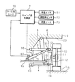
以下本発明をその実施の形態を示す図面に基づいて詳述する。図1は、本発明に係るキャンバ角制御装置の構成を示す模式図である。図中1は、操舵用の車輪、同じく2は、車輪1により懸架される車体であり、車輪1は、車体2の側面に設けられたホイールハウス20の内側に、アッパアーム3及びロアアーム4により支持されている。
Hereinafter, the present invention will be described in detail with reference to the drawings illustrating embodiments thereof. FIG. 1 is a schematic diagram showing a configuration of a camber angle control device according to the present invention. In the figure, 1 is a steering wheel, and 2 is a vehicle body suspended by a
車輪1は、ハブ10の軸心に突設された車軸11を介してナックル12に回転自在に支持されている。ナックル12は、上下に延設された支持アーム13,14を一体に備えており、上部の支持アーム13は、アッパアーム3の先端に、また下部の支持アーム14は、ロアアーム4の先端に、夫々ボールジョイントを介して連結されている。このように連結されたナックル12は、アッパアーム3及びロアアーム4に対する傾倒姿勢を変えつつ、両アーム3,4との連結部を結ぶキングピン軸Kを中心として回動することができる。
The
ホイールハウス20の内側に延びるアッパアーム3及びロアアーム4の基端部は、上下に離隔して位置する夫々のピボット30,40により、上下方向への揺動を自在として枢支されている。また下位置に枢支されたロアアーム4の中途部は、コイルばね及びダンパを同軸に備える公知の懸架ユニット5を介してホイールハウス20上部の車体2の一部に連結されており、ロアアーム4及びアッパアーム3の揺動は、前記コイルばねのばね力に抗して、また前記ダンパによる減衰下にてなされる懸架ユニット5の伸縮を伴って生じるように構成されている。
The base ends of the
以上の懸架方式は、例えば、車体2側のピボット30,40への枢支部が2股に分岐されたV字形のアッパアーム3及びロアアーム4を各1本用いてなるダブルウイッシュボーン式として公知の方式であるが、アッパアーム3及びロアアーム4の一方又は両方を、複数本のI字形アームを用いて構成することもできる。
The above suspension system is, for example, a system known as a double wishbone system using one V-shaped
またナックル12は、内側面から斜め前方又は斜め後方に向けて延設されたナックルアーム15を一体又は別体に備えている。このナックルアーム15は、タイロッド16を介して図示しない操舵機構に連結され、該操舵機構の動作によりタイロッド16を介して押し引きされるように構成されている。この押し引きによりナックル12は、キングピン軸Kを中心として回動し、この回動によりナックル12に支持された車輪1は、前記操舵機構の動作に応じて操舵される。
Further, the
更に、アッパアーム3の先端へのナックル12の連結部には、アッパアーム3の長手方向に移動可能なスライダ31が介装されており、該スライダ31は、タイロッド16の中途に基部を枢支されたキャンバ角調整用のアクチュエータ6の出力端に連結されている。このアクチュエータ6は、例えば、油圧の給排に応じて伸縮動作する油圧シリンダとすることができ、伸長時にアッパアーム3の先端側に向けてスライダ31を移動させ、また縮短時にアッパアーム3の基端側に向けてスライダ31を移動させるように構成されている。
Further, a
以上の如く支持された車輪1は、図に示すように、下部周面を路面Rに接地させて車体2を懸架し、車軸11を中心とする回転により路面R上にて転動して車両を走行させる。また車輪1は、前述の如く、タイロッド16によるナックルアーム15の押し引きに応じて、ナックル12と共にキングピン軸Kを中心として回動することにより操舵され、この操舵の方向に車両が旋回走行する。
As shown in the figure, the
この走行の間、車輪1と車体2とは、路面Rから車輪1に加わる反力、車体2に加わる遠心力等の外力の作用により上下方向に相対変位するが、この相対変位は、ばね及び減衰要素としての懸架ユニット5の伸縮を伴うアッパアーム3及びロアアーム4の揺動により吸収され、車体2は、安定した懸架姿勢を保つことができる。
During this travel, the
またこの走行の間、前述の如く配されたキャンバ角調整用のアクチュエータ6は、路面Rの垂直線に対する車輪1の傾斜角、即ち、キャンバ角を増減調節すべく伸縮動作せしめられる。図2は、アクチュエータ6の動作説明図である。
During this travel, the camber
図2(a)には、アクチュエータ6を縮短させた状態が示されている。この場合、アクチュエータ6の出力端に連結されたスライダ31は、図示の如くアッパアーム3の基端側に移動し、該アッパアーム3へのナックル12の連結部が、ロアアーム4への連結部よりも内側に変位することとなり、該ナックル12に支持された車輪1には、上部を内向きとして傾斜するキャンバ角(ネガティブキャンバ)が与えられる。
FIG. 2A shows a state where the
また図2(b)には、アクチュエータ6を伸長させた状態が示されている。この場合、アクチュエータ6の出力端に連結されたスライダ31は、図示の如くアッパアーム3の先端側に移動し、該アッパアーム3へのナックル12の連結部が、ロアアーム4への連結部よりも外側に変位することとなり、該ナックル12に支持された車輪1には、上部を外向きとして傾斜するキャンバ角(ポジティブキャンバ)が与えられる。
FIG. 2B shows a state where the
このように車輪1のキャンバ角は、アクチュエータ6の伸縮動作に応じて増減せしめられ、このようにキャンバ角が付与された車輪1には、図2中に矢符により示す如く、傾いている方向の横力(キャンバスラスト)FT が加わる。本発明においては、このように加わるキャンバスラストFT を、路面Rとの摩擦による車輪1の変形復元力としてのコーナリングフォースと共に車両の旋回を補助するための力として利用すべく、以下の如くキャンバ角制御が実行される。
Thus, the camber angle of the
なおアクチュエータ6は、前述の如く、操舵のために車輪1を押し引きするタイロッド16の中途に支持されているため、車輪1のキャンバ角は、タイロッド16の進退動作によるアクチュエータ6の支持部の移動によっても変化し、タイロッド16の進出側にてポジティブキャンバが、同じく退入側にてネガティブキャンバが夫々与えられる。ここで本発明においては、タイロッド16の進退動作による車輪1の操舵が、進出時に前方を外向きとして生じ、退入時に前方を内向きとして生じるように構成してある。これにより、操舵のためのタイロッド16の進退動作によるキャンバ角の変化は、旋回円外側の車輪1にネガティブキャンバが、旋回円内側の車輪1にポジティブキャンバが夫々与えられるように構成してある。
Since the
前記アクチュエータ6は、図1に示す如く、キャンバ角制御部7から与えられる動作指令に従って伸縮動作せしめられる。キャンバ角制御部7は、演算処理部としてのCPU、制御プログラムを記憶させてあるROM、及び演算に用いられる定数値、マップ等を記憶させてあるRAMを備える電子制御ユニットとして構成されており、該キャンバ角制御部7には、アクチュエータ6に付設されたストロークセンサ60から、該アクチュエータ6の伸縮位置の検出結果が与えられており、また車体2の適宜部位に設けたロール角センサ70から、車体2のロール角の検出結果が与えられている。
As shown in FIG. 1, the
ここでロール角とは、車両の旋回走行中に、遠心力の作用により旋回円の外側を下として車体2に生じる傾斜角度であり、ロール角センサ70は、ロール角に直接的に対応する出力が得られるフリージャイロにより構成することができ、また、レートジャイロの出力として与えられるロール角速度を積分した結果として検出する構成とすることもできる。
Here, the roll angle is an inclination angle generated in the
更にキャンバ角制御部7には、車両の走行速度の検出結果が車速センサ71から与えられており、また車輪1の操舵角の検出結果が、操舵角センサ72から与えられており、更に車輪1に加わる荷重の検出結果が荷重センサ73から与えられている。
Further, the camber
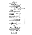
図3は、キャンバ角制御部7の動作内容を示すフローチャートである。このフローチャートに従うキャンバ角制御部7の動作は、車速センサ70による検出車速が予め設定された下限車速を超えている高速走行時に、所定の制御周期毎に繰り返し行われる動作であり、キャンバ角制御部7は、まず入力側に与えられる夫々のセンサの検出値を取り込み(ステップ1)、次いで、車輪1のキャンバ角を算出する(ステップ2)。
FIG. 3 is a flowchart showing the operation content of the camber
車輪1のキャンバ角は、前述の如く、アクチュエータ6の伸縮動作と、車輪1の操舵のためのタイロッド16の進退動作とに応じて変化すると共に、旋回走行時の遠心力の作用により車体2に生じるロールによっても変化し、旋回円の外側の車輪1には、ロール角に相当するポジティブキャンバが、旋回円の内側の車輪1には、ロール角に相当するネガティブキャンバが与えられる。
As described above, the camber angle of the
前記ステップ2でのキャンバ角の算出は、まず、操舵角センサ72の検出値として取り込まれた操舵角からタイロッド16の進退位置を求め、この結果とストロークセンサ60の検出値として取り込まれたアクチュエータ6の伸縮位置とを用いて車体2に対する車輪1のキャンバ角を求め、この結果をロール角センサ70の検出値として取り込まれたロール角に基づいて、旋回円外側の車輪1についてはポジティブ側に、旋回円の内側の車輪1についてはネガティブ側に夫々補正する手順にてなされる。
In the calculation of the camber angle in the
次いでキャンバ角制御部7は、ステップ2において算出されたキャンバ角と、荷重センサ73の検出値として取り込まれた車輪1への付加荷重とを用いて車輪1に加わるキャンバスラストFT を予測演算し(ステップ3)、また、車速センサ71及び操舵角センサ72の検出値として夫々取り込まれた車速及び操舵角と、前記キャンバ角及び付加荷重とを用いて車輪1に加わるコーナリングフォースFC を予測演算する(ステップ4)。
Then camber
図4は、キャンバスラストの発生挙動を示す図である。本図に示す如くキャンバスラストは、キャンバ角の増加に対して比例的に増加する特性を示し、その増加率の大小は、車輪1への付加荷重の大小に対応する。ステップ3におけるキャンバスラストFT の予測演算は、例えば、マップ化してRAMに記憶させてある図4に、キャンバ角及び付加荷重の検出値を適用してなされる。
FIG. 4 is a diagram illustrating the generation behavior of the canvas last. As shown in the figure, the canvas last exhibits a characteristic that increases in proportion to the increase in camber angle, and the magnitude of the increase rate corresponds to the magnitude of the applied load to the
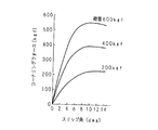
図5は、コーナリングフォースの発生挙動を示す図である。本図に示す如くコーナリングフォースは、車輪1のスリップ角の増加に対して比例的に増加し、上限スリップ角に達した時点で平衡する特性を示し、増加域での増加率の大小は、車輪1への付加荷重の大小に対応する。スリップ角は、車速及び操舵角を用いて算出することができ、ステップ4におけるコーナリングフォースFC の予測演算は、例えば、マップ化してRAMに記憶させてある図5に、スリップ角の算出値及び付加荷重の検出値を適用して標準値を求め、この値を、ポジティブ側及びネガティブ側に発生するキャンバ角に応じて減量補正する手順によりなされる。
FIG. 5 is a diagram illustrating the generation behavior of the cornering force. As shown in the figure, the cornering force increases in proportion to the increase of the slip angle of the
なお図4に示すキャンバスラストの発生挙動、及び図5に示すコーナリングフォースの発生挙動は、車輪1として使用されているタイヤの種類、該タイヤの空気圧等、タイヤの状態の影響を受けるから、例えば、夫々の発生挙動をタイヤの状態毎にマップ化し、対応するマップを選択的に用いてキャンバスラストFT 及びコーナリングフォースFC を予測演算するのが望ましい。
The generation behavior of the canvas last shown in FIG. 4 and the generation behavior of the cornering force shown in FIG. 5 are affected by the state of the tire, such as the type of tire used as the
次いでキャンバ角制御部7は、予測演算されたキャンバスラストFT 及びコーナリングフォースFC を加算し、旋回円の内側に向けて車輪1に作用する総コーナリングフォースF(=FT +FC )を算出する(ステップ5)。なおこのとき、常に旋回円の内側に向けて発生するコーナリングフォースFC は正値として取り扱い、車輪1の傾斜の方向に発生するキャンバスラストFT は、旋回円の内側の車輪1については、ポジティブキャンバによるものを正値とし、旋回円の外側の車輪1については、ネガティブキャンバによるものを正値として取り扱う。
Then camber
次いでキャンバ角制御部7は、キャンバ角を予め定めた単位幅毎に仮に増減し(ステップ6)、このキャンバ角が前記アクチュエータ6の動作による変更が可能な範囲にあるか否かを判定し(ステップ7)、変更可能な範囲にある場合(ステップ7:YES)には、ステップ3に戻り、夫々のキャンバ角を用いてキャンバスラストFT 、コーナリングフォースFC 及び総コーナリングフォースFを求める動作を繰り返す。
Next, the camber
一方、変更可能な範囲内でのキャンバ角の増減が完了した場合(ステップ7:NO)には、夫々における総コーナリングフォースFの算出値を比較し、この値が最大となるときのキャンバ角を最適キャンバ角として選定し(ステップ8)、この最適キャンバ角を実現すべくアクチュエータ6に動作指令を発し、該アクチュエータ6を伸縮動作させて(ステップ9)、一連の動作を終了する。
On the other hand, when the increase / decrease of the camber angle within the changeable range is completed (step 7: NO), the calculated values of the total cornering force F in each are compared, and the camber angle at which this value becomes maximum is determined. The optimum camber angle is selected (step 8), an operation command is issued to the
以上の動作により、アクチュエータ6の伸縮により実現可能な範囲の全域に亘って所定の幅毎にキャンバ角を変化させた場合の夫々において、キャンバスラストFT 及びコーナリングフォースFC が演算され、両者の和として与えられる総コーナリングフォースFを最大とするキャンバ角が最適キャンバ角として決定されることとなり、このように決定された最適キャンバ角がアクチュエータ6の伸縮動作により実現される。
By the above operation, in each of the case where the entire area in the range achievable by expansion and contraction of the
なお、キャンバ角の増減に応じた総コーナリングフォースFの変化は、連続した変化として生じるから、ステップ6においてキャンバ角を増加又は減少してステップ3に戻り、ステップ5において総コーナリングフォースFを算出する都度、この値を前回の算出値と比較して、前回値よりも小さい場合には、以降の増加又は減少側へのキャンバ角を変更を省略してもよい。これにより繰り返し回数を減少することができる。
Since the change in the total cornering force F according to the increase / decrease in the camber angle occurs as a continuous change, the camber angle is increased or decreased in
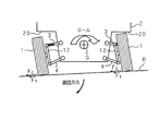
図6は、本発明に係るキャンバ角制御装置を備える車両の旋回走行時の状態を示す模式図である。図中に矢符にて示す向きに旋回走行するとき、車体2は、重心Gの回りに白抜矢符にて示す如くロールし、旋回円の外側の車輪1にはネガティブキャンバが、旋回円の内側の車輪1にはポジティブキャンバが夫々与えられ、コーナリングフォースFC と同向きのキャンバスラストFT が、これらの和(=FC +FT )を最大とするように加えられることとなり、旋回円の内側に向かうこれらの力の作用により車両は、確実にしかも安定して旋回走行せしめられる。
FIG. 6 is a schematic diagram illustrating a state during turning of a vehicle including the camber angle control device according to the present invention. When turning in the direction indicated by the arrow in the figure, the
ここで、以上の如くキャンバ角を付与すべく伸縮動作するアクチュエータ6は、操舵のために左右の車輪1,1を押し引きするタイロッド16の中途に支持されていることから、車輪1のキャンバ角は、対応するタイロッド16の進退動作によるアクチュエータ6の支持部の移動によっても変化し、この変化は、前述した如く、旋回円の外側の車輪1にネガティブキャンバが、旋回円の内側の車輪1にポジティブキャンバが夫々付与されるように、即ち、キャンバ角制御部7の前述した動作により実現されるキャンバ角と同向きのキャンバ角が付与されるように生じる。従って、キャンバ角制御部7において決定される最適キャンバ角は、アクチュエータ6をわずかな伸縮動作させることにより実現され.旋回走行中の状態変化に速やかに追随したキャンバ角制御が可能となる。
Here, the
1 車輪
2 車体
3 アッパアーム
4 ロアアーム
6 アクチュエータ
7 キャンバ角制御部(制御手段)
16 タイロッド
FC コーナリングフォース
FT キャンバスラスト
DESCRIPTION OF
16 Tie Rod F C Cornering Force F T Canvas Last
Claims (2)
前記制御手段は、
前記車両のロール角及び前記アクチュエータの動作量の検出結果に基づいて前記車輪のキャンバ角を算出するキャンバ角算出手段と、
前記車両の旋回状態の検出結果に基づいて前記車輪のスリップ角を算出するスリップ角算出手段と、
前記キャンバ角算出手段及びスリップ角算出手段の算出結果と、前記車輪に加わる荷重とに基づいて前記車輪に作用するコーナリングフォース及びキャンバスラストを予測演算する演算手段とを備え、
該演算手段により演算される前記コーナリングフォース及びキャンバスラストの予測値の和を最大とすべく前記アクチュエータを動作させる構成としてあることを特徴とするキャンバ角制御装置。 The vehicle body is suspended and supported via an upper arm and a lower arm, a steering wheel connected to a steering mechanism via a tie rod, an actuator for increasing or decreasing a camber angle of the wheel, and the actuator is operated when the vehicle is turning, In a camber angle control device for a vehicle, comprising control means for increasing / decreasing the camber angle of the wheel to obtain a desired turning performance,
The control means includes
Camber angle calculating means for calculating a camber angle of the wheel based on a detection result of a roll angle of the vehicle and an operation amount of the actuator;
Slip angle calculating means for calculating a slip angle of the wheel based on a detection result of the turning state of the vehicle;
Computation means for predicting and calculating the cornering force and canvas last acting on the wheel based on the calculation result of the camber angle calculation means and the slip angle calculation means, and the load applied to the wheel,
A camber angle control device characterized in that the actuator is operated so as to maximize the sum of the predicted values of the cornering force and canvas last calculated by the calculating means.
Priority Applications (1)
| Application Number | Priority Date | Filing Date | Title |
|---|---|---|---|
| JP2005176849A JP2006347399A (en) | 2005-06-16 | 2005-06-16 | Camber angle control device |
Applications Claiming Priority (1)
| Application Number | Priority Date | Filing Date | Title |
|---|---|---|---|
| JP2005176849A JP2006347399A (en) | 2005-06-16 | 2005-06-16 | Camber angle control device |
Publications (1)
| Publication Number | Publication Date |
|---|---|
| JP2006347399A true JP2006347399A (en) | 2006-12-28 |
Family
ID=37643681
Family Applications (1)
| Application Number | Title | Priority Date | Filing Date |
|---|---|---|---|
| JP2005176849A Pending JP2006347399A (en) | 2005-06-16 | 2005-06-16 | Camber angle control device |
Country Status (1)
| Country | Link |
|---|---|
| JP (1) | JP2006347399A (en) |
Cited By (3)
| Publication number | Priority date | Publication date | Assignee | Title |
|---|---|---|---|---|
| JP2011093425A (en) * | 2009-10-29 | 2011-05-12 | Equos Research Co Ltd | Control device for vehicle |
| KR101263051B1 (en) | 2007-12-10 | 2013-05-09 | 현대자동차주식회사 | Wish Bone type suspension for vehicle |
| CN112829821A (en) * | 2019-11-22 | 2021-05-25 | 财团法人工业技术研究院 | Steering device and method |
-
2005
- 2005-06-16 JP JP2005176849A patent/JP2006347399A/en active Pending
Cited By (5)
| Publication number | Priority date | Publication date | Assignee | Title |
|---|---|---|---|---|
| KR101263051B1 (en) | 2007-12-10 | 2013-05-09 | 현대자동차주식회사 | Wish Bone type suspension for vehicle |
| JP2011093425A (en) * | 2009-10-29 | 2011-05-12 | Equos Research Co Ltd | Control device for vehicle |
| CN112829821A (en) * | 2019-11-22 | 2021-05-25 | 财团法人工业技术研究院 | Steering device and method |
| CN112829821B (en) * | 2019-11-22 | 2022-06-21 | 财团法人工业技术研究院 | Steering apparatus and method |
| US11548552B2 (en) | 2019-11-22 | 2023-01-10 | Industrial Technology Research Institute | Steering device and method thereof |
Similar Documents
| Publication | Publication Date | Title |
|---|---|---|
| JP2009035081A (en) | Control device | |
| JP2008055921A (en) | Vehicle rear wheel toe angle variable control device | |
| JP4821454B2 (en) | Vehicle travel control device | |
| JP2009090762A (en) | Suspension device | |
| JP2008302813A (en) | Strut suspension system | |
| JP4806930B2 (en) | Vehicle steering system | |
| JP5056303B2 (en) | Control device | |
| JP2006062505A (en) | Vehicle suspension system | |
| JP2006347399A (en) | Camber angle control device | |
| JP4996956B2 (en) | Steering characteristic control device | |
| JP5086943B2 (en) | Vehicle steering system | |
| JP5338620B2 (en) | Vehicle control device | |
| JP4844194B2 (en) | vehicle | |
| JP2009073350A (en) | Control device | |
| JP2019026195A (en) | Vehicle suspension system | |
| JPS5970258A (en) | Auxiliary steering device of rear wheel | |
| JP2005170196A (en) | Vehicle suspension system | |
| JPH07228124A (en) | Stabilizer device of vehicle | |
| JP2007210374A (en) | Vehicle steering control device and steering device | |
| JP5162491B2 (en) | Rear seat control device for vehicle | |
| KR101297961B1 (en) | Toe control apparatus for active geometry control rear suspension in vehicle and control method thereof | |
| JP2008105599A (en) | Suspension device, automobile and vehicle motion control method | |
| JP2009090972A (en) | Control device | |
| JP2007030566A (en) | Control device and vehicle | |
| JPH0518165Y2 (en) |